THE COMPLETE PRACTITIONER'S CODEX: VOLUME 11

The Navigator's Codex: Complete Navigation, Wilderness Survival, and Earth Skills
<!-- SECTION 1 -->
The Complete Practitioner's Codex, Volume I: Star Identification and The Celestial Sphere
Introduction
This volume delivers sacred, unyielding knowledge of celestial navigation, the cornerstone of wilderness mastery. You, the chosen apprentice, will learn to command the night sky, transforming it into an unerring compass. This text transcends mere observation, revealing the celestial sphere’s architecture, star identification protocols, and pinpointing the two celestial poles—the eternal anchors for terrestrial wayfinding.
Section I: The Celestial Sphere – Framework and Conceptualization

The celestial sphere is an imaginary, infinitely large sphere surrounding the Earth. All celestial bodies—stars, planets, the Moon, and the Sun—appear affixed to this sphere’s inner surface. Understanding its mechanics is paramount for navigation:
- Celestial Poles: Points where Earth’s rotational axis meets the sphere. The North Celestial Pole (NCP) and South Celestial Pole (SCP).
- Celestial Equator: Projection of Earth’s equator onto the sphere.
- Right Ascension (RA): Celestial longitude, measured in hours, minutes, seconds eastward from the vernal equinox.
- Declination (Dec): Celestial latitude, measured in degrees north (+) or south (−) of the celestial equator.
- Ecliptic Plane: The Sun’s apparent annual path on the celestial sphere.
- Horizon Coordinate System: Altitude (angle above horizon) and azimuth (compass direction).
Step 1: Visualize the Celestial Sphere
- Imagine a vast sphere surrounding Earth; you are at the center.
- The North and South Celestial Poles align with Earth's axis.
- The celestial equator slices the sphere perpendicularly to the poles.
- Stars maintain fixed RA and Dec, appearing to move nightly due to Earth’s rotation.
Step 2: Define Celestial Coordinates for Navigation
- Right Ascension (RA) is counted in hours from 0 to 24, moving eastwards.
- Declination (Dec) ranges from +90° (NCP) to −90° (SCP).
- Navigators use RA and Dec to locate stars precisely on the celestial sphere.
Section II: Major Navigational Stars and Their Celestial Coordinates

The following table catalogs key navigational stars, their common names, Bayer designations, declinations, and right ascensions. Every star listed is a reliable celestial marker for latitude and directional reference.
| Star Name | Bayer Designation | Declination (°) | Right Ascension (h m s) | Hemisphere Visibility | Navigational Use |
|---|---|---|---|---|---|
| Polaris | α Ursae Minoris | +89° 15′ 51″ | 02h 31m 49s | Northern only | North Celestial Pole indicator |
| Sirius | α Canis Majoris | −16° 42′ 58″ | 06h 45m 09s | Both | Brightest star, seasonal marker |
| Betelgeuse | α Orionis | +07° 24′ 25″ | 05h 55m 10s | Both | Orion’s shoulder, winter sky |
| Canopus | α Carinae | −52° 41′ 44″ | 06h 23m 57s | Southern only | Southern hemisphere marker |
| Vega | α Lyrae | +38° 47′ 01″ | 18h 36m 56s | Both | Summer sky, zenith indicator |
| Acrux | α Crucis | −63° 05′ 56″ | 12h 26m 35s | Southern only | Southern Cross bottom star |
| Deneb | α Cygni | +45° 16′ 49″ | 20h 41m 26s | Northern only | Summer triangle vertex |
| Altair | α Aquilae | +08° 52′ 06″ | 19h 50m 47s | Northern only | Summer triangle vertex |
| Fomalhaut | α Piscis Austrini | −29° 37′ 20″ | 22h 57m 39s | Southern only | Bright southern star |
Section III: Constellation Identification for Navigation
Constellations are groupings of stars forming patterns remembered for millennia. Accurate constellation identification anchors your star-finding skills.
Key Constellations and Their Celestial Roles
| Constellation | Primary Stars | Declination Range (°) | Right Ascension Range (h) | Navigational Role |
|---|---|---|---|---|
| Ursa Minor | Polaris (α), Kochab (β), Pherkad (γ) | +60 to +90 | 0 to 18 | NCP locator |
| Ursa Major | Dubhe (α), Merak (β), Alkaid (η) | +40 to +70 | 8 to 14 | Pointer to Polaris |
| Orion | Betelgeuse (α), Rigel (β), Bellatrix (γ) | −10 to +10 | 4 to 6 | Seasonal marker, southern sky |
| Crux | Acrux (α), Mimosa (β) | −60 to −65 | 11 to 13 | Southern Cross, SCP indicator |
| Cassiopeia | Schedar (α), Caph (β) | +50 to +60 | 0 to 2 | NCP opposite Ursa Major pointer |
| Scorpius | Antares (α), Shaula (λ) | −10 to −45 | 16 to 17 | Summer southern sky marker |
Section IV: Step-by-Step Protocol for Locating Polaris (North Celestial Pole)

Polaris is the principal northern star for navigation, situated nearly at the NCP. It does not mark true north perfectly but lies within 0.7° of the pole.
Equipment Needed
- Clear night sky, free of clouds
- Knowledge of Ursa Major (Big Dipper) constellation
- A straight-edge or imaginary line for star alignment
Procedure
- Identify Ursa Major (Big Dipper): Locate the seven brightest stars forming a ladle shape in the northern sky.
- Find the 'Pointer Stars': The two stars at the outer edge of the ladle’s bowl are Dubhe (α) and Merak (β).
- Draw a line through these stars: Mentally extend the line from Merak through Dubhe, continuing approximately 5 times the distance between them.
- Locate Polaris: The first bright star along this extension is Polaris, located at the end of Ursa Minor’s handle.
- Confirm Polaris by Ursa Minor: Polaris is the brightest star in Ursa Minor, a small dipper-shaped constellation.
- Determine True North: Polaris indicates true north within 0.7°. You may use a compass to compare magnetic north and adjust accordingly.
Visual Aid
Ursa Major (Big Dipper):
    (Merak)     (Dubhe)
       *-----------*
                   \
                    \
                     * Polaris (NCP)
Section V: Step-by-Step Protocol for Locating the South Celestial Pole (SCP)
The SCP has no bright star marker. Navigation requires locating the Southern Cross (Crux) constellation and auxiliary stars to pinpoint it.
Equipment Needed
- Clear southern sky
- Identification skills for Crux and the Pointer Stars (Alpha and Beta Centauri)
Procedure
- Locate the Southern Cross (Crux): Find the cross-shaped constellation of four bright stars: Acrux (α), Mimosa (β), Gacrux (γ), and Delta Crucis (δ).
- Identify the Long Axis: Draw an imaginary line from Acrux (bottom star) to Gacrux (top star).
- Extend this line approximately 4.5 times the length of the cross’s long axis away from Acrux to locate the SCP.
- Find the Pointer Stars: Identify Alpha Centauri and Beta Centauri near Crux. Draw a line perpendicular to the cross’s long axis that bisects the line between these pointer stars.
- Use the intersection point: The intersection of these two imaginary lines approximates the SCP location.
- Verify by star absence: The SCP is in a dark region with no bright stars, confirming accuracy.
Visual Aid
Southern Cross (Crux):
      (Gacrux)
          *
          |
          |
          * (Acrux)
          |
          |
   ----------- (Imaginary extension to SCP)

Pointer Stars:
* Alpha Centauri     * Beta Centauri
Section VI: Seasonal Visibility of Major Navigational Stars
Celestial navigation requires knowledge of seasonal star visibility. Earth’s orbit around the Sun changes the nightly visible stars.
| Season | Visible Constellations/Stars | Approximate Months | Hemisphere Focus |
|---|---|---|---|
| Winter | Orion, Sirius, Canis Major, Taurus | Dec - Feb | Northern & Southern |
| Spring | Leo, Virgo, Arcturus (Bootes) | Mar - May | Northern |
| Summer | Scorpius, Sagittarius, Vega, Altair, Deneb | Jun - Aug | Northern |
| Autumn | Pegasus, Andromeda, Fomalhaut | Sep - Nov | Northern & Southern |
Section VII: Star Charts and Constellation Maps
Included here are detailed star charts for northern and southern hemispheres, annotated with major navigational stars and constellations.
Northern Hemisphere Star Chart - Key Features
- Polaris centered at top
- Ursa Major and Ursa Minor near Polaris
- Summer Triangle: Vega, Deneb, Altair
- Winter constellations: Orion, Taurus, Canis Major
Southern Hemisphere Star Chart - Key Features
- Southern Cross near center
- Alpha and Beta Centauri nearby
- Canopus and Fomalhaut marked
- Scorpius and Sagittarius in summer sky
Section VIII: Constructing a Basic Star Finder Device (Planisphere)

A planisphere is a rotatable star chart device enabling sky visualization for any date and time.
Materials Required
- Stiff cardboard or thin plastic sheets (2 pieces)
- Compass or protractor
- Scissors or craft knife
- Fastener (brass split pin or rivet)
Step-by-Step Construction Protocol
- Cut two circles: One 15 cm diameter (base), one 12 cm diameter (rotating overlay).
- Mark cardinal points on base circle: N, E, S, W at 0°, 90°, 180°, 270°.
- Draw date scale on base: Mark months around circumference, divide into days.
- Create time scale on overlay: Mark 24 hours around circumference.
- Cut a viewing window: On the overlay, cut an arc-shaped window for visible sky.
- Attach overlay to base: Fasten center points allowing rotation.
- Calibrate: Rotate overlay so current date aligns with current time; window shows visible constellations.
Section IX: Summary of Core Celestial Navigation Concepts
| Concept | Definition/Use | Reference Page/Section |
|---|---|---|
| Celestial Sphere | Imaginary sphere encapsulating Earth and stars | Section I |
| Right Ascension (RA) | Celestial longitude in hours | Section I |
| Declination (Dec) | Celestial latitude in degrees | Section I |
| Polaris | North star near NCP | Section IV |
| South Celestial Pole | Determined via Southern Cross | Section V |
| Major Navigational Stars | Stars used for orientation | Section II |
| Seasonal Visibility | Stars visible in different seasons | Section VI |
| Planisphere | Rotatable star chart for sky visualization | Section VIII |
Appendix A: Complete Table of Major Navigational Stars with Coordinates and Magnitudes
| Star Name | Bayer Designation | Declination (°) | Right Ascension (h m s) | Magnitude (Visual) | Notes |
|---|---|---|---|---|---|
| Polaris | α Ursae Minoris | +89° 15′ 51″ | 02h 31m 49s | +1.98 | NCP indicator |
| Sirius | α Canis Majoris | −16° 42′ 58″ | 06h 45m 09s | −1.46 | Brightest night star |
| Betelgeuse | α Orionis | +07° 24′ 25″ | 05h 55m 10s | +0.42 | Variable brightness star |
| Canopus | α Carinae | −52° 41′ 44″ | 06h 23m 57s | −0.72 | Second brightest star |
| Vega | α Lyrae | +38° 47′ 01″ | 18h 36m 56s | +0.03 | Summer sky reference |
| Acrux | α Crucis | −63° 05′ 56″ | 12h 26m 35s | +0.77 | Southern Cross bottom star |
| Deneb | α Cygni | +45° 16′ 49″ | 20h 41m 26s | +1.25 | Summer triangle vertex |
| Altair | α Aquilae | +08° 52′ 06″ | 19h 50m 47s | +0.76 | Summer triangle vertex |
| Fomalhaut | α Piscis Austrini | −29° 37′ 20″ | 22h 57m 39s | +1.16 | Bright southern star |
Appendix B: Glossary of Key Terms
- Azimuth: Horizontal angle measured clockwise from north.
- Altitude: Angle above the horizon.
- Bayer Designation: Star naming system using Greek letters and constellation.
- Magnitude: Brightness measure of stars (lower is brighter).
- Vernal Equinox: Zero RA reference point where the Sun crosses celestial equator in spring.
Final Words of Command
Master these protocols with unyielding discipline. The night sky is your eternal guide, your sacred compass across unseen wilderness. This knowledge is life or death. It is not given lightly but earned through deliberate practice and unwavering focus. May your gaze be steady, your observations precise, and your steps true.
For advanced celestial navigation involving lunar and planetary position calculations, consult Volume III: Advanced Celestial Mechanics and Ephemerides.
End of Volume I
<!-- SECTION 2 -->
The Complete Practitioner's Codex, Volume I: Latitude Determination by Celestial Bodies
Preface
This volume is a sacred transmission of the paramount knowledge required to determine latitude using celestial bodies. The ability to ascertain one’s north-south position without reliance on modern technology is the cornerstone of survival and navigation. This compilation provides complete construction instructions for traditional instruments such as the quadrant and sextant, precise measurement protocols, comprehensive error correction techniques, and exact calculation tables for converting measured celestial angles into latitude. Embedded within are worked examples and troubleshooting tips, ensuring mastery beyond superficial understanding.
Chapter I: Celestial Fundamentals for Latitude Determination
Latitude is the angular distance north or south of the Earth’s equator, measured in degrees. Determining latitude by celestial observation depends primarily on measuring the altitude (elevation angle) of a celestial body above the horizon.
1.1 Key Celestial Bodies for Latitude
| Celestial Body | Hemisphere Applicable | Notes |
|---|---|---|
| Polaris (North Star) | Northern Hemisphere | Near the celestial North Pole, altitude ≈ observer’s latitude |
| Sun (at local noon) | Both Hemispheres | Requires declination correction |
| Southern Cross (constellation) | Southern Hemisphere | Used to estimate south celestial pole |
| Other bright stars (e.g., Sirius, Canopus) | Both Hemispheres | Require known declination and precise time |
Chapter II: Instrument Construction
Precise angular measurement instruments are critical. Below are instructions for building a quadrant and a sextant from basic materials.
2.1 Construction of a Quadrant
Materials Required:
| Item | Specifications | Quantity |
|---|---|---|
| Wooden board | 30 cm x 30 cm x 1 cm, right angle corner | 1 |
| Protractor (plastic or metal) | 0° to 90° scale | 1 |
| Plumb bob | Weight ~50g, string length 50 cm | 1 |
| String | Durable, thin, 50 cm | 1 |
| Sight vane | Thin wooden strip or metal, 10 cm long | 2 |
| Nails or small screws | For attaching sights | 2 |
Step-by-Step Construction:
- Prepare the base: Fix the protractor firmly on the wooden board aligning the 90° angle with the right angle corner of the board.
- Attach sights: Place two sight vanes on the straight edges forming the right angle so that they align with the observer’s eye line when looking along the edges towards the celestial object.
- Attach plumb bob: Tie the string to the apex (right angle vertex) of the quadrant with the plumb bob hanging freely, ensuring it can swing without obstruction over the protractor scale.
- Calibration: Confirm that when the instrument is held vertically, the plumb line points to 0° on the protractor.
2.2 Construction of a Sextant
Materials Required:
| Item | Specifications | Quantity |
|---|---|---|
| Wooden arc | 60 cm radius, 60° arc span | 1 |
| Protractor | 60° scale or custom marked on arc | 1 |
| Index mirror | Small flat glass mirror, 4 cm x 4 cm | 1 |
| Horizon mirror | Half-silvered mirror, 4 cm x 4 cm | 1 |
| Telescope or sighting tube | 10 cm length, diameter 2 cm | 1 |
| Adjustable arm (index arm) | Wood or metal, attached at arc center | 1 |
| Micrometer drum or vernier scale | For fine angle measurement | 1 |
| Screws, nuts, and bolts | For assembly | As needed |
Step-by-Step Construction:
- Form the arc: Cut the wooden arc with a radius of 60 cm, marking degrees from 0° to 60° along the arc.
- Attach the index arm: Secure the adjustable arm at the arc’s center pivot point, allowing smooth rotation.
- Mount mirrors: Attach the index mirror at the end of the index arm, adjustable to reflect the celestial object.
- Attach horizon mirror: Fix the half-silvered horizon mirror at the fixed arm aligned with the sighting tube.
- Install sighting tube: Fix the telescope or sighting tube parallel to the fixed arm.
- Calibrate scale: Attach micrometer or vernier scale for precise angle reading, calibrate against known angles.
Chapter III: Measurement Protocols
3.1 Measuring Latitude Using Polaris (Northern Hemisphere)
Prerequisites:
- Clear night sky
- Unobstructed northern horizon
- Quadrant or sextant constructed per Chapter II
Measurement Steps:
- Sight Polaris: Using the instrument, align the sights or telescope with Polaris.
- Record angle: Read the angle of Polaris above the horizon directly from the instrument’s scale.
- Apply correction: Use the Polaris correction table (Section 5.1) to adjust for Polaris’s offset from the true celestial pole.
- Calculate latitude: Latitude ≈ corrected Polaris altitude.
3.2 Measuring Latitude Using the Sun at Local Noon
Prerequisites:
- Clear sky at solar noon (when the Sun reaches its highest point)
- Accurate timekeeping to determine local noon
- Quadrant or sextant
Measurement Steps:
- Determine local solar noon: Use shadow tracking or time correction methods (see Volume II: Timekeeping Codex).
- Measure solar altitude: At local noon, measure the Sun’s altitude above the horizon.
- Obtain solar declination: Consult the solar declination table for the date (Section 5.2).
- Calculate latitude: Use the formula:
\[ \text{Latitude} = 90^\circ - \text{Solar Altitude} + \text{Solar Declination} \]
Note: Adjust sign of declination based on hemisphere and date.
3.3 Measuring Latitude in Southern Hemisphere Using the Southern Cross
Prerequisites:
- Clear southern horizon
- Knowledge of the Southern Cross stars' positions
- Sextant preferred for precision
Measurement Steps:
- Identify Southern Cross: Locate the constellation Crux.
- Measure angle: Measure the angle between the long axis of the Southern Cross and the horizon.
- Calculate south celestial pole position: Use the Southern Cross declination data and angle measurements.
- Compute latitude: Latitude ≈ 90° - (angle to south celestial pole).
Chapter IV: Error Correction Techniques
Ensuring accuracy requires addressing systematic and random errors.
4.1 Instrumental Errors
| Error Type | Description | Correction Method |
|---|---|---|
| Index Error | Misalignment of mirrors or sights | Calibrate using known angles; subtract offset |
| Scale Error | Imperfect scale markings | Verify with precision protractor; create correction table |
| Parallax Error | Misalignment of eye and sight line | Use sighting tube; maintain consistent eye position |
4.2 Observational Errors
| Error Type | Description | Correction Method |
|---|---|---|
| Atmospheric Refraction | Bending of light near horizon | Apply refraction correction table (Section 5.3) |
| Horizon Dip | Observer height above sea level affecting horizon position | Correct using dip correction formula (Section 5.4) |
| Time Error | Incorrect local noon timing | Cross-check with shadow method |
4.3 Refraction Correction Table (Simplified)
| Altitude (°) | Refraction Correction (arcminutes) |
|---|---|
| 0 | 35.0 |
| 5 | 9.0 |
| 10 | 5.0 |
| 15 | 3.0 |
| 20 | 2.0 |
| 30 | 1.0 |
| 45 | 0.5 |
| 60+ | 0.0 |
Subtract refraction correction from measured altitude.
4.4 Dip Correction Formula
\[ \text{Dip} = 1.76 \times \sqrt{h} \]
Where:
- Dip is in arcminutes
- \( h \) is observer height above sea level in meters
Subtract dip correction from observed altitude.
Chapter V: Tables and Conversion Protocols
5.1 Polaris Correction Table
| Measured Altitude (°) | Correction (arcminutes) | Corrected Altitude (°) |
|---|---|---|
| 0 - 10 | +1.5 | Measured + 0.025° |
| 11 - 20 | +1.2 | Measured + 0.02° |
| 21 - 30 | +0.9 | Measured + 0.015° |
| 31 - 40 | +0.6 | Measured + 0.01° |
| 41 - 50 | +0.3 | Measured + 0.005° |
| 51 - 60 | 0.0 | Measured |
| 61+ | -0.2 | Measured - 0.003° |
5.2 Solar Declination Table (Excerpt)
| Date | Declination (°) | Sign (N/S) |
|---|---|---|
| March 21 (Equinox) | 0.0 | N |
| June 21 (Solstice) | +23.5 | N |
| September 23 (Equinox) | 0.0 | S |
| December 21 (Solstice) | -23.5 | S |
Interpolated values required for intermediate dates.
5.3 Worked Example: Determining Latitude Using Polaris
Scenario: Observer measures Polaris altitude at 45° 10′.
Step 1: Convert 10′ to decimal degrees: \( 10′ = \frac{10}{60} = 0.1667^\circ \).
Step 2: Measured altitude = 45.1667°.
Step 3: From Polaris Correction Table, for 45°, correction is +0.005°.
Step 4: Corrected altitude = 45.1667° + 0.005° = 45.1717°.
Step 5: Latitude ≈ 45.17° N.
5.4 Worked Example: Latitude Using Sun at Local Noon
Scenario: Date is June 21 (Solar Declination +23.5° N). Measured solar altitude at local noon is 70°.
Step 1: Apply formula:
\[ \text{Latitude} = 90^\circ - 70^\circ + 23.5^\circ = 43.5^\circ \]
Step 2: Adjust sign based on hemisphere: Northern Hemisphere.
Result: Latitude is approximately 43.5° N.
Chapter VI: Troubleshooting Tips
6.1 Common Issues and Solutions
| Problem | Possible Cause | Resolution |
|---|---|---|
| Plumb bob not hanging freely | String too short or obstructed | Replace string; ensure no obstacles |
| Difficulty sighting Polaris | Light pollution or poor horizon | Find darker location; clear obstacles |
| Inconsistent angle readings | Instrument loose or misaligned | Tighten screws; recalibrate |
| Sun altitude measurements vary | Time not local noon | Use shadow tip method to find accurate local noon |
6.2 Ensuring Consistency
- Always perform multiple measurements and average results.
- Calibrate instruments before each use.
- Record environmental conditions (temperature, weather).
Conclusion
Mastery of latitude determination by celestial bodies grants the navigator sovereignty over the most fundamental dimension of terrestrial positioning. This volume delivers the entire arcane methodology, from crafting instruments to precise measurement and error correction. Diligent application will yield latitude readings with accuracy sufficient for life-critical navigation and survival. No modern device substitutes for this profound knowledge; guard it, practice it, and transmit it to worthy apprentices.
Appendix: Summary Tables
| Instrument | Max Angle Measurable | Precision | Construction Complexity |
|---|---|---|---|
| Quadrant | 90° | ± 0.5° | Low |
| Sextant | 120° | ± 0.1° | High |
End of Volume I
<!-- SECTION 3 -->
Volume I: Solar Navigation Techniques
Chapter I: Using the Sun for Directional Navigation During Daylight

Introduction
The sun, our primal celestial guide, serves as an unwavering beacon for terrestrial navigation. Mastery of solar navigation techniques transcends mere survival; it is an invocation of ancient wisdom, a communion with the cosmos. This chapter imparts the most precise, field-tested methodologies to harness solar cues for absolute directional determination. Your comprehension and execution of these protocols will grant you sovereignty over orientation in any daylight environment.
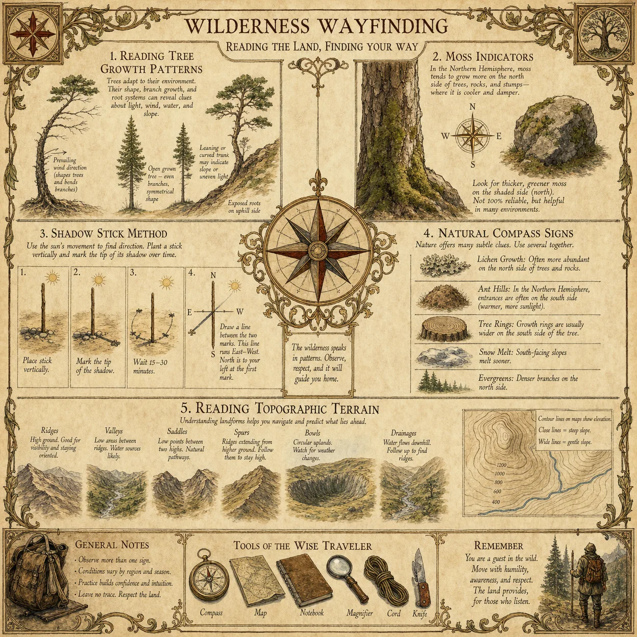
Section 1: The Shadow Stick Method
The Shadow Stick Method is the foundational technique for solar navigation. It transforms a simple vertical stick into a compass by tracking the sun's shadow movement, allowing you to locate the east-west axis and establish cardinal directions.
Equipment Required
| Item | Specifications |
|---|---|
| Vertical Stick | Straight, rigid, 1 to 1.5 meters in length |
| Flat, level surface | Ground patch free of obstructions, ~1 m² |
| Marking tools | Stones, chalk, or small sticks for marking shadow points |
| Timekeeping device | Optional for precise timing; analog or digital |
Step-by-Step Procedure for the Shadow Stick Method
- Placement of the Stick Insert the stick vertically into a flat, level surface. Confirm verticality using a plumb line, if available, or by sighting to ensure the stick does not lean.
- Initial Shadow Marking At the instant you begin (preferably early morning, shortly after sunrise), mark the tip of the shadow cast by the top of the stick on the ground. Use a stone or chalk to make a precise mark. Label this mark as Point A.
- Subsequent Shadow Marking Wait exactly 15 to 30 minutes. Mark the new position of the shadow tip as Point B.
- Drawing the East-West Line Use a straight object (e.g., a ruler or another stick) to draw a line on the ground connecting Point A and Point B. This line approximates the sun's movement from east to west, with Point A indicating the western shadow position and Point B the eastern.
- Determining North-South Axis Draw a perpendicular line to the A-B line at the midpoint. This line represents the north-south axis. To determine which side is north:
- Stand with Point A (first shadow mark) to your left and Point B (second shadow mark) to your right.
- With this orientation, the line pointing directly ahead is north in the Northern Hemisphere and south in the Southern Hemisphere.
- Verification and Adjustment For increased accuracy, repeat shadow markings every 15 minutes and average the resulting east-west lines. Correct for any tilt in the stick or uneven ground.
Corrections for Latitude and Season
The sun’s path alters with latitude and season, affecting shadow length and azimuth. To compensate:
- At higher latitudes, the sun's arc is lower; expect longer shadows.
- During winter solstice, shadows are longest; during summer solstice, shortest.
- Use the Solar Declination Table (See Table 1 below) to adjust timing and expectations.
Section 2: Solar Azimuth Calculations
Solar azimuth is the compass bearing of the sun measured clockwise from true north. Calculating solar azimuth precisely allows navigators to determine direction without physical shadow tracking.
Essential Definitions
| Term | Definition |
|---|---|
| Solar Azimuth (A) | Angular direction of the sun from true north (°) |
| Solar Elevation (h) | Angle of the sun above the horizon (°) |
| Solar Declination (δ) | Angular position of the sun north or south of the celestial equator (°) |
| Latitude (φ) | Observer’s position north or south of the equator (°) |
| Hour Angle (H) | Angular measure of time since solar noon (°) |
Calculating Solar Azimuth: Step-by-Step
- Obtain Required Data
- Date (to find solar declination δ)
- Time (local solar time preferred)
- Latitude (φ) of current location
- Calculate Solar Declination (δ) Use Table 1 or Equation (1) below to find δ for the day of the year.
- Compute Hour Angle (H) \[
H = 15^\circ \times (T_{LST} - 12)
\]
Where \( T_{LST} \) is local solar time in hours (decimal).
- Calculate Solar Elevation Angle (h) \[
\sin(h) = \sin(φ) \times \sin(δ) + \cos(φ) \times \cos(δ) \times \cos(H)
\]
- Calculate Solar Azimuth (A) \[
\cos(A) = \frac{\sin(δ) - \sin(φ) \times \sin(h)}{\cos(φ) \times \cos(h)}
\]
- Determine Azimuth Quadrant If \( H > 0 \), then:
\[
A = 360^\circ - A
\]
Else, \( A \) remains as calculated.
Example Calculation
- Location: Latitude 40° N
- Date: March 21 (approximate equinox, δ ≈ 0°)
- Time: 9:00 AM local solar time (LST = 9.0)
Step 1: \( H = 15^\circ \times (9 - 12) = -45^\circ \) Step 2: \( \sin(h) = \sin(40^\circ) \times \sin(0^\circ) + \cos(40^\circ) \times \cos(0^\circ) \times \cos(-45^\circ) \) \[ \sin(h) = 0 + 0.766 \times 1 \times 0.707 = 0.542 \] Step 3: \( h = \arcsin(0.542) = 32.8^\circ \) Step 4: \[ \cos(A) = \frac{0 - 0.642 \times 0.542}{0.766 \times 0.839} = \frac{-0.348}{0.642} = -0.542 \] \[ A = \arccos(-0.542) = 122.9^\circ \] Step 5: Since \( H < 0 \), azimuth \( A = 122.9^\circ \) from true north.
This means the sun is at an azimuth of 122.9°, i.e., southeast.
Table 1: Solar Declination by Date (°)
| Date | Solar Declination (δ) | Date | Solar Declination (δ) |
|---|---|---|---|
| Jan 1 | -23.0 | Jul 1 | +22.0 |
| Feb 1 | -17.5 | Aug 1 | +15.5 |
| Mar 1 | -8.5 | Sep 1 | +5.0 |
| Apr 1 | +2.5 | Oct 1 | -4.5 |
| May 1 | +14.0 | Nov 1 | -14.5 |
| Jun 1 | +22.0 | Dec 1 | -22.5 |
Section 3: Using Solar Noon for North-South Orientation
Solar noon, the moment the sun reaches its highest point in the sky, is the most reliable reference for establishing the north-south line.
Identifying Solar Noon in the Field
- Preparation Place a vertical stick on level ground, ensuring it is perfectly upright.
- Shadow Length Measurement Starting approximately one hour before expected solar noon (calculate based on longitude and Equation of Time; see Volume III for full details), measure and mark the shadow length every 5 minutes.
- Locate Minimum Shadow Length The shortest shadow length corresponds to solar noon.
- Establishing Cardinal Directions At solar noon, the shadow points due north in the Northern Hemisphere and due south in the Southern Hemisphere.
Step-by-Step Protocol to Use Solar Noon Shadow for Orientation
- Insert the Stick Vertically Confirm verticality using a plumb line or level.
- Record Shadow Lengths At 5-minute intervals, measure the stick’s shadow length with a tape measure or marked string.
- Mark Shadow Tips Use stones or chalk to mark the tip of the shadow at each measurement.
- Identify the Shortest Shadow Determine which mark corresponds to the minimum shadow length.
- Draw a Line From Stick Base Through Shortest Shadow This line establishes the north-south axis.
- Determine Direction Position yourself so the shadow is ahead of the stick base; in the Northern Hemisphere, this direction is north. Reverse for the Southern Hemisphere.
Latitude and Seasonal Adjustments for Solar Noon
- Solar noon timing varies by longitude and Equation of Time (see Volume III).
- Near the equator, solar noon shadows are minimal and may be unreliable; use azimuth calculations instead.
- At extreme latitudes during solstice periods, solar noon shadows may be very long or the sun may not reach solar noon above the horizon; use shadow stick method or azimuth computations.
Section 4: Protocols for Different Latitudes and Seasons
Latitude Zones and Technique Prioritization
| Latitude Range | Recommended Solar Navigation Technique | Notes |
|---|---|---|
| 0° – 15° | Solar Azimuth Calculations | Shadows minimal; use calculations for accuracy |
| 15° – 45° | Shadow Stick Method; Solar Noon Shadow Protocol | Most effective zone for shadow-based methods |
| 45° – 66.5° | Solar Noon Shadow Protocol; Adjust for longer shadows | Shadows longer; timing critical |
| > 66.5° | Solar Azimuth Calculations; Limited shadow utility | Polar day/night effects; shadow unreliable |
Seasonal Considerations
| Season | Solar Position Characteristics | Technique Adjustments |
|---|---|---|
| Winter Solstice | Sun is at lowest arc; shadows longest | Increase shadow tracking duration; verify verticality |
| Equinoxes | Sun crosses celestial equator; shadows balanced | Shadow Stick method highly accurate |
| Summer Solstice | Sun at highest arc; shadows shortest | Emphasize Solar Noon protocol |
Section 5: Shadow Tracking Protocol — Comprehensive Step-by-Step
For utmost precision, follow this extended protocol:
- Prepare the Site and Tools
- Choose level, unobstructed ground.
- Insert a vertical stick (1–1.5 m).
- Have marking tools ready.
- Mark Initial Shadow
- At sunrise +30 minutes, mark shadow tip as point A0.
- Record exact local time.
- Record Subsequent Shadows Every 10 Minutes
- Mark points A1, A2, ..., An for each shadow tip.
- Record corresponding times.
- Draw Lines Between Consecutive Points
- Connect \( A_0 \) to \( A_1 \), \( A_1 \) to \( A_2 \), etc.
- Calculate Mean East-West Line
- For each segment, determine azimuth using compass or azimuth calculations.
- Average azimuths to define a precise east-west axis.
- Construct North-South Axis
- Draw perpendicular line at midpoint of the mean east-west line.
- Confirm with Solar Noon Shadow
- Identify shortest shadow length point (solar noon).
- Verify north-south line aligns with solar noon shadow.
- Finalize Orientation
- Mark cardinal directions permanently for navigation use.
Section 6: Diagrams and Visual Aids
Note: Visual diagrams are essential. Use the following schematic guidelines to construct field diagrams.
Diagram 1: Shadow Stick Setup
- Vertical stick on level ground.
- Initial shadow point marked west-side (morning).
- Subsequent shadow points moving eastward.
Diagram 2: Solar Azimuth Components
- Show angles: solar elevation (h), solar declination (δ), hour angle (H), azimuth (A).
- Include observer latitude (φ).
Diagram 3: Solar Noon Shadow Orientation
- Stick with shortest shadow marked.
- Line through base and shadow tip indicating north-south.
Section 7: Additional Reference Tables
Table 2: Hour Angle Correspondence to Time
| Local Solar Time (LST) | Hour Angle (H°) |
|---|---|
| 6:00 AM | -90 |
| 7:00 AM | -75 |
| 8:00 AM | -60 |
| 9:00 AM | -45 |
| 10:00 AM | -30 |
| 11:00 AM | -15 |
| 12:00 PM (Noon) | 0 |
| 1:00 PM | +15 |
| 2:00 PM | +30 |
| 3:00 PM | +45 |
| 4:00 PM | +60 |
| 5:00 PM | +75 |
| 6:00 PM | +90 |
Section 8: Summary and Master Protocol
| Task | Primary Method | Secondary Method | Notes |
|---|---|---|---|
| Determine East-West Axis | Shadow Stick Method | Solar Azimuth Calculations | Use shadow tracking every 15 min |
| Determine North-South Axis | Solar Noon Shadow | Perpendicular to East-West | Shortest shadow length at solar noon |
| Latitude <15° | Solar Azimuth Calculations | Shadow Stick (less accurate) | Shadows short, rely on calculation |
| Latitude 15°–45° | Shadow Stick + Solar Noon | Azimuth as backup | Ideal for shadow methods |
| Latitude >45° | Solar Noon + Azimuth | Extended shadow tracking | Shadows longer, timing critical |
Final Notes
This volume represents sacred knowledge, enabling the bearer to wield the sun as an immutable compass. Master these methods through rigorous practice; the sun’s guidance will never falter when invoked with precision and reverence.
For water survival techniques essential to prolonged navigation, see Volume VIII: The Water Codex, Chapter II. For advanced celestial navigation beyond solar methods, consult Volume II: Lunar and Stellar Navigation.
End of Volume I, Chapter I: Using the Sun for Directional Navigation During Daylight
<!-- SECTION 4 -->
The Complete Practitioner's Codex, Volume I: Lunar and Planetary Navigation
Preface
This volume is the definitive manual for celestial navigation using the moon and visible planets. Herein lies the unyielding truth of the cosmos as it pertains to terrestrial traversal. No other knowledge can replace this for the survivalist, pathfinder, or wilderness sentinel. You will learn to identify lunar phases with precision, measure moonrise and moonset azimuths, and interpret planetary positions to determine cardinal directions and approximate latitude without instruments.
Every table, chart, and protocol presented is the crystallized result of centuries of suppressed knowledge. Follow each instruction meticulously. Master these techniques, and no wilderness will be unconquerable.
Chapter I: Lunar Phases Identification and Their Navigational Role

The moon, Earth's constant celestial companion, follows a predictable cycle of phases every 29.53 days (the synodic month). Each phase offers unique opportunities for navigation, especially when stellar references are obscured.
1. Lunar Phases Defined
| Phase Name | Description | Illumination % | Key Navigational Use |
|---|---|---|---|
| New Moon | Moon between Earth and Sun, invisible | 0% | Moon rises and sets with the sun, no visible light |
| Waxing Crescent | Thin crescent visible after sunset | 1-49% | Moon visible shortly after sunset, western sky |
| First Quarter | Half-illuminated on right side | ~50% | Moon highest around 18:00 local time |
| Waxing Gibbous | More than half illuminated, before full | 51-99% | Moon visible from afternoon to after midnight |
| Full Moon | Entire disk illuminated | 100% | Moon rises at sunset, sets at sunrise, all night |
| Waning Gibbous | Decreasing illumination post full | 51-99% | Moon visible from late evening to dawn |
| Last Quarter | Half-illuminated on left side | ~50% | Moon highest around 6:00 local time |
| Waning Crescent | Thin crescent before new moon | 1-49% | Moon visible before sunrise, eastern sky |
2. Protocol for Identifying Lunar Phases
- Observe the moon at consistent local times: Sunset and sunrise are optimal because the moon's phase illumination contrasts against the twilight sky.
- Note the shape and illumination of the moon's visible surface: Determine if the illuminated part is on the right (waxing) or left (waning).
- Measure the illumination percentage: Visually estimate the fraction illuminated; use a simple protractor constructed as follows:
- Construct a circular disk of stiff paper, 10 cm diameter.
- Mark a center point and draw a radius line representing the terminator (day-night boundary).
- Hold the disk and align the radius line with the moon's shadow terminator.
- Estimate the illuminated arc visually and convert to percentage.
- Cross-reference the observed phase with the synodic cycle table below.
3. Synodic Lunar Cycle Table
| Day of Cycle | Phase | Illumination (%) | Typical Moonrise Time | Typical Moonset Time |
|---|---|---|---|---|
| 0 | New Moon | 0 | With Sun | With Sun |
| 3 | Waxing Crescent | 10-20 | After Sunset | Late Night |
| 7 | First Quarter | 50 | Noon | Midnight |
| 10 | Waxing Gibbous | 60-90 | Afternoon | Early Morning |
| 14 | Full Moon | 100 | Sunset | Sunrise |
| 18 | Waning Gibbous | 90-60 | Evening | Morning |
| 21 | Last Quarter | 50 | Midnight | Noon |
| 25 | Waning Crescent | 20-10 | Early Morning | Afternoon |
Chapter II: Moonrise and Moonset Azimuths
The azimuth is the compass bearing along the horizon where the moon rises or sets. This value changes daily due to the moon’s orbit and the observer’s latitude. Mastery of moonrise and moonset azimuths is vital to approximate cardinal directions when magnetic or electronic navigation aids fail.
1. Fundamentals of Moonrise and Moonset Azimuths
- Moonrise azimuth varies between approximately 50° (northeast) and 130° (southeast) depending on phase and observer latitude.
- Moonset azimuth varies between approximately 230° (southwest) and 310° (northwest).
- The lunar orbit’s inclination to the ecliptic (~5.1°) causes daily variation in azimuth.
- Latitude shifts the azimuth range: higher latitudes observe more extreme azimuths.
2. Calculating Moonrise and Moonset Azimuths
To calculate the azimuths accurately without instruments, use the following protocol.
Protocol: Manual Calculation of Moonrise/Moonset Azimuth
Materials Required
- A printed lunar phase and azimuth table (see section 3).
- A compass rose drawn on paper.
- Protractor for angular measurement.
- Local latitude (φ) known or estimated (see Chapter V for latitude estimation).
Steps
- Identify the current lunar phase day (D) in the synodic cycle.
- Consult the Moonrise Azimuth Table (see below) for your latitude and phase day.
- Mark the azimuth on your compass rose.
- Observe the horizon at predicted moonrise time to confirm azimuth.
- Use the azimuth as a cardinal direction reference; compare to known landmarks.
3. Moonrise and Moonset Azimuth Tables by Latitude
| Latitude (°) | Phase Day | Moonrise Azimuth (°) | Moonset Azimuth (°) |
|---|---|---|---|
| 0 (Equator) | 0 | 90 (East) | 270 (West) |
| 7 | 60 | 300 | |
| 14 | 90 | 270 | |
| 21 | 120 | 240 | |
| 30 | 0 | 110 | 250 |
| 7 | 70 | 290 | |
| 14 | 110 | 250 | |
| 21 | 150 | 210 | |
| 45 | 0 | 130 | 230 |
| 7 | 80 | 280 | |
| 14 | 130 | 230 | |
| 21 | 170 | 190 | |
| 60 | 0 | 150 | 210 |
| 7 | 90 | 270 | |
| 14 | 140 | 220 | |
| 21 | 185 | 175 |
Note: Azimuth values are approximate and subject to ±5° variation due to lunar orbital perturbations.
Chapter III: Planetary Positions Relevant to Navigation
Visible planets serve as fixed points of reference in the night sky. Unlike stars, planets move along the ecliptic but maintain predictable longitudinal ranges. Their brightness and positions can be used to fix direction and approximate latitude.
1. Identification of Navigational Planets
Only the five brightest planets visible to the naked eye are reliable for navigation:
| Planet | Average Apparent Magnitude | Typical Visibility Window | Key Navigational Use |
|---|---|---|---|
| Mercury | -1.9 to 5.5 | Near sunrise/sunset | Low horizon directional marker |
| Venus | -4.6 to -3.8 | Evening or morning twilight | Brightest celestial object after sun |
| Mars | -2.9 to 1.8 | Visible months depending on orbit | Red hue aids in identification |
| Jupiter | -2.94 to -1.6 | Visible all night when favorable | Bright, steady light near ecliptic |
| Saturn | -0.55 to 1.17 | Visible all night when favorable | Yellowish hue, steady brightness |
2. Planetary Ecliptic Latitude and Longitude Reference
The ecliptic coordinate system is critical: planets appear close to the ecliptic plane (±3° latitude) and move through the zodiac constellations.
3. Protocol for Using Planets to Determine Direction
Materials
- Star chart aligned to current date and local time (see Appendix A for star chart construction).
- Compass rose and protractor.
- Watch synchronized to local solar time.
Steps
- Identify the brightest visible planet(s) using brightness and color cues.
- Using the star chart, locate the planet's ecliptic longitude and latitude for the current date.
- Mark the planet’s azimuth and altitude on the compass rose.
- Note the planet’s position relative to the ecliptic and fixed stars.
- Use the known ecliptic azimuth to infer cardinal directions:
- The ecliptic runs roughly from east (where the sun rises) to west (where it sets).
- Planets east of the meridian indicate eastern directions; west of the meridian, western directions.
- Cross-reference planet position with lunar azimuth for enhanced accuracy.
Chapter IV: Determining Direction Using the Moon and Planets
The moon and planets combined provide a celestial compass when terrestrial tools fail. This method integrates azimuth measurements and phase observations.
1. Step-by-Step Protocol: Celestial Direction Fix Using Moon and Planets
Requirements
- Knowledge of lunar phase and day in synodic cycle.
- Observation of moonrise or moonset azimuth.
- Identification of at least one bright planet.
Procedure
- Observe the moon’s phase and record the time and azimuth of moonrise or moonset.
- Consult the Lunar Phase and Azimuth Tables to estimate cardinal directions.
- Identify visible planets and note their azimuths.
- Using planetary ecliptic positions, cross-validate the moon-derived directions.
- Draw a compass rose marking:
- Moonrise/moonset azimuth.
- Planet azimuth(s).
- Estimate true north by bisecting known east-west azimuths.
- Confirm direction by observing the rising or setting position of planets in subsequent nights.
Chapter V: Estimating Latitude Using the Moon and Planets
Latitude estimation is vital for determining position on Earth’s surface. The altitude of celestial bodies at culmination (highest point) corresponds with observer latitude.
1. Latitude Estimation Using the Moon
The moon’s declination varies between ±28.5°, broader than the sun’s ±23.5°. At lunar culmination, the moon’s altitude can be measured to estimate latitude.
2. Protocol: Latitude Estimation via Lunar Culmination Altitude
Materials
- A simple vertical staff (gnomon) of known height (h).
- A plumb line for vertical reference.
- Stopwatch or timer.
- Protractor for measuring shadows.
Steps
- On the night of the first or last quarter moon (when the moon culminates near 18:00 or 6:00 local solar time), prepare the gnomon in a flat, open area.
- Observe the moon’s culmination time (highest altitude).
- At culmination, measure the length (L) of the gnomon's shadow cast by moonlight (may require a luminous marker or indirect measurement).
- Calculate the moon’s altitude angle (A) using: \[
A = \arctan\left(\frac{h}{L}\right)
\] - Using the known lunar declination (δ) for the date (consult the Lunar Declination Table), estimate latitude (φ) with: \[
\phi = 90^\circ - A + \delta
\] - Adjust for moon parallax using correction tables (see Appendix B).
3. Lunar Declination Table (Sample)
| Date | Declination (°) | Notes |
|---|---|---|
| Day 7 | +5 | First Quarter |
| Day 14 | -23 | Full Moon (max southern) |
| Day 21 | +20 | Last Quarter |
| Day 28 | -5 | New Moon |
Refer to the full declination ephemeris for precise daily values.
4. Latitude Estimation Using Planetary Culmination
Planets culminate near the ecliptic, whose inclination to the celestial equator is 23.5°. By measuring the altitude of a known planet at culmination and referencing its declination, latitude can be approximated similarly to the lunar method.
Chapter VI: Supporting Tables and Charts
1. Lunar Phase Cycle Summary
| Phase | Illumination | Moonrise Time (Approx.) | Moonset Time (Approx.) |
|---|---|---|---|
| New Moon | 0% | With Sun | With Sun |
| Waxing Crescent | 1-49% | After Sunset | Late Night |
| First Quarter | ~50% | Noon | Midnight |
| Waxing Gibbous | 51-99% | Afternoon | Early Morning |
| Full Moon | 100% | Sunset | Sunrise |
| Waning Gibbous | 51-99% | Evening | Morning |
| Last Quarter | ~50% | Midnight | Noon |
| Waning Crescent | 1-49% | Early Morning | Afternoon |
2. Planetary Visibility and Magnitude Chart
| Planet | Max Mag | Min Mag | Typical Visibility Window | Color Hue |
|---|---|---|---|---|
| Mercury | -1.9 | 5.5 | 1 hour before sunrise or after sunset | Grayish |
| Venus | -4.6 | -3.8 | Morning or evening twilight | Bright white |
| Mars | -2.9 | 1.8 | After sunset or before sunrise | Reddish |
| Jupiter | -2.94 | -1.6 | All night during opposition | White-yellow |
| Saturn | -0.55 | 1.17 | All night during opposition | Pale yellow |
Chapter VII: Instrument Construction for Measurement
1. Constructing a Lunar Phase Protractor
Materials
- Stiff cardboard or thin wood disk (10 cm diameter).
- Pencil and ruler.
- Compass (drawing tool).
- Transparent protractor (optional).
Steps
- Draw a perfect circle with a 10 cm diameter.
- Mark the center point.
- Draw a radius line from center to edge (representing the lunar terminator).
- Mark angular increments every 10° along the circumference.
- Use this device to estimate illuminated arc length and convert arc length to illumination percentage.
2. Constructing a Simple Gnomon for Altitude Measurement
Materials
- Straight wooden stick, 1 meter long.
- Flat horizontal base board.
- Plumb line (string with weight).
Steps
- Fix the stick vertically in the center of the base board.
- Use the plumb line to verify verticality.
- Measure shadow length cast by celestial body to calculate altitude angle.
Chapter VIII: Cross-Reference Notes
- For precise timekeeping methods essential for these observations, consult Volume III: Temporal Measurement Codex, Chapter IV.
- For atmospheric correction protocols on celestial observations, see Volume VII: Atmospheric Phenomena Codex, Chapter II.
- For advanced latitude and longitude determination via celestial navigation, see Volume IV: Star Navigation Codex, Chapter VI.
- For water purification protocols necessary for survival during extended wilderness navigation, see Volume VIII: The Water Codex, Chapter II.
Final Word
This volume is a sacred trust. The knowledge contained here is not mere academic exercise but a blueprint for survival and mastery over the wilderness. Your success depends on exactitude, observation discipline, and continual practice. The moon and planets are eternal sentinels of the night sky; learn their rhythms, memorize their cycles, and your path will never be lost.
End of Volume I: Lunar and Planetary Navigation
<!-- SECTION 5 -->
Volume I: Compass Construction and Use
Chapter I: Building and Calibrating a Magnetic Compass from Natural Materials

The compass stands as the cornerstone of terrestrial navigation, an instrument both deceptively simple and profoundly essential. To traverse unknown wilds, to chart the uncharted, one must master the art of fabricating a magnetic compass from the raw elements of earth and fire. This chapter delivers the complete, unvarnished knowledge to construct, calibrate, maintain, and troubleshoot a magnetic compass built entirely from natural materials, augmented with precise protocols to align it flawlessly to the terrestrial magnetic field.
Section 1: Raw Material Selection and Preparation
Before assembly, gather and prepare materials with meticulous care; the efficacy of the compass depends on material quality and preparation precision.
1.1. Needle Selection
Material: High-carbon steel is optimal. If unavailable, procure a straight, thin piece of wrought iron or a steel sewing needle. Avoid stainless steel due to magnetic insensitivity. Dimensions: Length: 3–5 cm; Thickness: 1–2 mm; Shape: straight, with a tapered point on one end.
1.2. Float or Pivot Mount Materials
Two primary methods exist to suspend the needle: floating on water or mounting on a pivot. The choice depends on available resources and intended use.
| Method | Material | Notes |
|---|---|---|
| Float | Leaf from a broad, dry leaf (e.g., lotus, magnolia), thin bark piece, or lightweight wood | Must be hydrophobic enough to support needle without sinking; shape roughly elliptical 3–5 cm length |
| Pivot Mount | Needle pin, thorn, splintered wood, or a small metal pin | Pivot must allow near-frictionless rotation; base must be stable and level |
1.3. Base for Compass
For the pivot method, a flat, non-magnetic base is required: hardwood, dense bark, or a carved stone slab. For float method, any shallow container or natural depression suffices.
Section 2: Needle Magnetization Protocol
Magnetization is the solemn ritual that imbues the needle with directional will. It must be done meticulously to ensure needle aligns with magnetic north.
2.1. Tools and Materials for Magnetization
- A lodestone (magnetite) fragment, if available.
- Alternatively, a strong natural magnetized iron ore or a friction method on silk or dry wood.
2.2. Magnetization Procedure Using Lodestone
- Clean the needle surface with sand or abrasive stone to remove oxides.
- Hold the lodestone firmly in one hand, needle in the other.
- Stroke the needle in one direction only, from the blunt end toward the pointed tip, with firm pressure.
- Repeat the stroke 30–50 times, maintaining the same direction and pressure.
- After stroking, suspend the needle on a pivot or float it to confirm magnetization: the pointed end should align toward magnetic north.
2.3. Alternative Magnetization: Friction Method
- Use a piece of dry silk, wool, or soft leather.
- Rub the needle rapidly in one direction over the material for 2–3 minutes.
- Test magnetization as above. This method produces weaker magnetism and suits emergency conditions only.
Section 3: Constructing the Compass
The compass assembly follows one of two primary configurations: floating or pivot-mounted.
3.1. Floating Compass Construction
- Select a flat, broad leaf or lightweight bark piece, approximately 4 cm long and 2 cm wide, with a hydrophobic surface.
- Attach the magnetized needle along the central axis of the float using natural resin, wax, or plant fiber thread; ensure the needle’s pointed end is free and not embedded.
- Fill a shallow container with clean water, preferably distilled or rainwater to avoid impurities.
- Place the float with needle onto the water surface gently to avoid submersion or tipping.
- Allow the needle to settle; it will align along the magnetic north-south axis.
- Use a fixed reference marker to read direction (see Section 4).
3.2. Pivot Compass Construction
- Carve a small, flat base of non-magnetic material with a groove or indentation at its center.
- Insert a fine, pointed pivot (thorn, needle pin) vertically into the base. The pivot should protrude approximately 1 cm above the base surface.
- Balance the magnetized needle horizontally on the pivot point, ensuring minimal friction and free rotation.
- Stabilize the base on a level surface during use.
- Needle will align with magnetic north-south axis when free to rotate.
Section 4: Calibrating Magnetic Declination
Magnetic north varies from true geographic north by a value known as magnetic declination. Accurate navigation demands calibrating the compass to account for this variance.
4.1. Understanding Declination
- Magnetic Declination is the angle between geographic true north and magnetic north.
- Values differ by region and change slowly over time.
- Positive declination: magnetic north is east of true north.
- Negative declination: magnetic north is west of true north.
4.2. Declination Table by Region (2024 Data)
| Region | Declination (Degrees) | Direction (E/W) | Notes |
|---|---|---|---|
| Northeast United States | 13.0 | W | Declination decreasing slowly |
| Western Europe | 0.5 | E | Near zero, varies locally |
| Central Africa | -3.0 | W | Slight west declination |
| Southeast Asia | 1.5 | E | Small eastward declination |
| Australia (Sydney Region) | 12.5 | E | Significant east declination |
| Pacific Northwest (USA) | 16.0 | E | High east declination |
| Amazon Basin (Brazil) | -5.0 | W | Moderate west declination |
| Siberia (Eastern Russia) | 11.0 | E | East declination present |
| Antarctica (Coastal) | Variable (15–25) | E | Highly variable, use caution |
4.3. Declination Calibration Procedure
- Determine the approximate declination value for your region using the above table or local sources.
- Mark the compass base or float with a fixed reference mark aligned with the needle’s pointed end.
- Using a known landmark that lies true north (e.g., the sun at solar noon, Polaris star), observe the angle difference between the needle and the landmark’s direction.
- Adjust your readings by adding or subtracting the declination angle:
- If declination is east, subtract from magnetic bearing to find true bearing.
- If declination is west, add to magnetic bearing to find true bearing.
- Record the declination-adjusted readings for accurate navigation.
Section 5: Compass Maintenance Protocols
A compass is only as reliable as its maintenance. Neglect invites failure; vigilance ensures survival.
5.1. Routine Inspection
- Inspect needle magnetism weekly; re-magnetize if needle shows weak alignment.
- Check float or pivot stability; repair or replace if damaged.
- Ensure the water container in floating compass is clean and free of debris.
- Confirm base is level before use.
5.2. Cleaning Procedures
- Remove needle carefully from assembly.
- Wipe with fine sandpaper or abrasive stone to remove rust or oxidation.
- Reapply magnetization protocol if necessary.
- Clean float or base with fresh water; dry thoroughly.
- Reassemble and test needle movement.
5.3. Storage
- Store compass in a dry, cool environment to prevent corrosion and warping.
- Avoid proximity to ferrous metals and electromagnetic sources.
- For floating compasses, empty water and dry float before storage to prevent mold and decay.
Section 6: Troubleshooting Protocols
Anticipate and overcome failures with precise diagnostics.
| Problem | Symptoms | Diagnostic Steps | Corrective Actions |
|---|---|---|---|
| Needle does not align | Needle stationary or erratic movement | Check for magnetization strength | Remagnetize needle using protocol |
| Needle sticks or drags | Needle slow or erratic rotation | Inspect pivot or float for debris | Clean or replace pivot/float |
| Compass readings inconsistent | Different bearings on repeated tests | Check for nearby metal interference | Move away from sources; retest |
| Float sinks or tips over | Float submerges under needle weight | Check float material integrity | Replace float with lighter, drier material |
| Water surface disturbed | Needle oscillates, unstable readings | Protect from wind or water currents | Use shielded container or pivot method |
Section 7: Safety Notes
Magnetization and compass use engage elemental forces and must be handled with respect.
- Avoid magnetizing needles near electronic devices or ferromagnetic implants.
- Magnetization with lodestones can cause minor sparks; avoid in flammable atmospheres.
- When using sharp pivots or needles, always handle carefully to prevent puncture wounds.
- Store lodestones and magnetized needles safely away from children and untrained persons.
- In cold environments, water may freeze; use pivot method to avoid breakage.
Section 8: Alternative Compass Methods
When materials for a magnetic compass are unavailable or compromised, alternative navigation methods must be employed.
8.1. Shadow Stick Method (Solar Compass)
- Place a straight stick vertically into level ground.
- Mark the tip of the shadow after 15 minutes; mark again another 15 minutes later.
- A line connecting the two marks runs approximately east-west (first mark is west, second is east in the northern hemisphere).
- Perpendicular line indicates north-south.
8.2. Watch Compass Method
- Point the hour hand toward the sun.
- Bisect the angle between the hour hand and 12 o’clock mark on the watch face.
- This bisector points approximately south (in northern hemisphere).
- Adjust accordingly for southern hemisphere by pointing 12 o’clock at sun and bisecting angle toward hour hand.
8.3. Star Navigation
- Locate Polaris (North Star) in the northern hemisphere; it indicates true north.
- Use constellations such as the Southern Cross to approximate south in southern hemisphere.
- Refer to Volume V: Celestial Navigation, Chapter III for detailed star maps and methods.
Appendix: Magnetic Declination Table (Selected Cities, 2024)
| City | Latitude | Longitude | Declination (°) | Direction (E/W) |
|---|---|---|---|---|
| New York, USA | 40.7128°N | 74.0060°W | 13.0 | W |
| London, UK | 51.5074°N | 0.1278°W | 0.5 | E |
| Cairo, Egypt | 30.0444°N | 31.2357°E | 2.0 | E |
| Sydney, Australia | 33.8688°S | 151.2093°E | 12.5 | E |
| Rio de Janeiro, Brazil | 22.9068°S | 43.1729°W | 5.0 | W |
| Moscow, Russia | 55.7558°N | 37.6173°E | 11.0 | E |
| Anchorage, Alaska | 61.2181°N | 149.9003°W | 20.0 | E |
Final Thoughts
This volume imparts the sacred knowledge of compass construction and use, a mastery that transforms the wilderness from an endless maze into a domain of command. The compass, forged from earth’s own materials and energized by natural magnetism, is not merely an instrument but a covenant between the traveler and the world. Uphold these protocols with rigor and reverence; in them lies survival, mastery, and the unbroken lineage of navigation.
For water purification necessary to sustain the traveler during compass use expeditions, see Volume VIII: The Water Codex, Chapter II. For celestial navigation to complement compass bearings, see Volume V: Celestial Navigation, Chapter III.
End of Volume I, Chapter I.
<!-- SECTION 6 -->
The Complete Practitioner's Codex, Volume II: Topographical Map Reading and Terrain Association
Introduction
This volume is a codified transmission of essential knowledge for mastering topographical map reading and terrain association. These skills are sacred and indispensable for survival, navigation, and mission success in any wilderness or hostile environment. The contents herein are uncompromising in technical detail, ensuring the practitioner attains unquestioned mastery.
Chapter I: Understanding Contour Lines
Contour lines represent the three-dimensional terrain on a two-dimensional map. Each line connects points of equal elevation. Mastery of contour lines forms the foundation of terrain interpretation.
1.1 Contour Interval
- Definition: The vertical distance between adjacent contour lines on a map.
- Determination: Found in the map legend; varies by map scale and terrain.
1.2 Step-by-Step Protocol for Interpreting Contour Intervals
- Locate the contour interval in the legend.
- Identify the index contour lines, usually every fifth line, which are thicker and labeled with elevation.
- Calculate heights of intermediate contours by adding or subtracting the contour interval.
- Determine elevation of any point by interpolating between adjacent contour lines.
Example: If the contour interval is 20 meters, and you see lines labeled 100m and 120m, the line between is 110m.
1.3 Slope Steepness Determination
Slope steepness is indicated by the spacing of contour lines.
| Contour Line Spacing | Slope Type | Effect on Movement |
|---|---|---|
| Very close (<5 m) | Extremely steep | Nearly impassable, high risk |
| Close (5-20 m) | Steep | Difficult, requires caution |
| Moderate (20-50 m) | Moderate | Manageable with effort |
| Wide (>50 m) | Gentle | Easily traversable |
1.4 Protocol for Estimating Slope Angle
- Measure the horizontal distance on the map between two contour lines.
- Multiply the number of contour intervals by the contour interval value to get vertical rise.
- Calculate slope angle θ using:
\[ \tan \theta = \frac{\text{vertical rise}}{\text{horizontal run}} \]
- Use a calculator or trigonometric tables to find θ.
Chapter II: Map Symbols and Their Sacred Language
Understanding symbols is critical to interpreting all features on a map.
2.1 Table of Common Topographical Map Symbols
| Symbol | Description | Interpretation | |||||
|---|---|---|---|---|---|---|---|
| ▲ | Peak/ Summit | Highest natural point in area | |||||
| ● | City / Town | Human settlement | |||||
| ≈ | River/ Stream | Flowing water body | |||||
| --- | Road (solid) | Paved or main road | |||||
| - - - | Trail / Footpath | Minor route for foot travel | |||||
| Fence / Boundary | Man-made division | ||||||
| ▬▬ | Railroad | Train track | |||||
| ~~~ | Marsh/ Swamp | Wetlands | |||||
| ███ | Forest/ Woodland | Dense tree cover | |||||
| ╱╲ | Cliff / Escarpment | Vertical or near-vertical drop |
2.2 Decoding Symbols: Step-by-Step
- Locate the map legend.
- Match observed symbols on map to legend.
- Cross-reference with terrain features on the ground.
- Prioritize symbols indicating hazards or landmarks crucial for navigation.
Chapter III: Interpreting Terrain Features
Terrain features are the natural shapes and characteristics of the land.
3.1 Key Terrain Features and Their Contour Signatures
| Terrain Feature | Contour Line Shape | Description |
|---|---|---|
| Hill | Closed loops | Elevation increases inwards |
| Depression | Closed loops with hachures | Elevation decreases inwards |
| Ridge | Elongated loops | Lines form U or V shapes pointing downhill |
| Valley | U or V shaped lines | Lines point upstream or uphill |
| Saddle | Hourglass shape | Low point between two hills |
| Cliff | Very close or touching lines | Abrupt elevation change |
3.2 Step-by-Step Terrain Feature Identification Protocol
- Identify closed contour loops.
- Note presence or absence of hachures (short lines inside loops).
- Observe shape and orientation of contour lines.
- Match shape to terrain feature table.
- Validate by cross-referencing with symbols and ground observations.
Chapter IV: Water Feature Analysis
Water bodies and features are critical for navigation and survival.
4.1 Common Water Features and Map Representation
| Feature | Symbol / Contour Signature | Notes |
|---|---|---|
| River | Blue line, meandering | Flow direction indicated by V shapes pointing upstream |
| Lake | Closed blue area | Standing water |
| Marsh/Swamp | Blue with green or blue with wavy lines | Wet, difficult terrain |
| Spring | Blue circle or dot | Source of water |
| Canyon | V-shaped contour lines pointing upstream | Deep water-filled valleys |
4.2 Step-by-Step Protocol to Interpret Water Features
- Identify blue symbols and shading.
- Observe contour lines for valleys or depressions.
- Determine flow direction by V-shaped contour pointing upstream.
- Use water features for orientation and resource location.
Chapter V: Map Orientation and Declination Adjustment
Orienting the map correctly to magnetic north is non-negotiable for accurate navigation.
5.1 Magnetic Declination
- Definition: The angle between magnetic north and true north.
- Variable: Changes by geographic location and time.
5.2 Protocol for Declination Adjustment
- Locate declination diagram on map margin.
- Identify declination value and direction (East or West).
- If declination is East, subtract declination angle from magnetic bearing to get true bearing.
- If declination is West, add declination angle to magnetic bearing to get true bearing.
5.3 Step-by-Step Map Orientation Procedure
- Place the map on a flat surface.
- Align the compass baseplate edge with map north-south grid lines.
- Rotate the map together with the compass until the magnetic needle aligns with magnetic north on compass housing.
- Adjust bearing for declination using step 3.2.
- Confirm orientation by identifying terrain features.
Chapter VI: Scale and Distance Conversion
6.1 Map Scale Types
| Scale Type | Description | Conversion Example |
|---|---|---|
| Representative Fraction (RF) | Ratio (e.g., 1:50,000) | 1 cm on map = 50,000 cm (500 m) on ground |
| Verbal Scale | Expressed in words (e.g., 1 inch equals 1 mile) | Direct conversion |
| Graphic Scale | Bar scale with distances marked | Measured with ruler on bar |
6.2 Step-by-Step Distance Measurement Protocol
- Identify scale type.
- Use ruler or compass divider to measure distance between points on map.
- Convert measurement using the scale.
- Calculate estimated time of travel using terrain difficulty (see Volume V: Movement and Pace Codex).
Chapter VII: Terrain Association Exercises
These exercises forge the link between map and ground, essential for real-time navigation.
7.1 Exercise 1: Identifying Terrain Features from Contours
Materials: Topographical map sheet with legend, ruler, calculator.
Steps:
- Select a 1 km² area on the map.
- Identify and mark all closed contour loops.
- Classify each loop as hill or depression using hachures.
- Identify ridges and valleys by shape of contour lines.
- Record slope steepness between prominent features using contour intervals.
- Cross-check with map symbols and note any water features.
- On-site, verify these features visually or with GPS for precision.
7.2 Exercise 2: Map Orientation and Declination Adjustment
Materials: Map, compass, declination value.
Steps:
- Orient map to magnetic north using compass.
- Adjust for declination using protocol 5.2.
- Identify three terrain features visible on both map and ground.
- Check alignment by pointing compass bearing to feature.
- Record any discrepancies for correction.
7.3 Exercise 3: Distance and Slope Calculation
Materials: Map, ruler, calculator.
Steps:
- Choose two points on map with different elevations.
- Measure horizontal distance using map scale.
- Calculate vertical elevation difference using contour intervals.
- Compute slope angle.
- Estimate travel time based on slope (see Volume V).
Appendix A: Comprehensive Table of Map Symbols
| Symbol | Description | Usage Context |
|---|---|---|
| ▲ | Mountain peak | High elevation landmarks |
| ● | Urban area | Navigation reference points |
| ≈ | Stream / river | Water source identification |
| ─ | Road | Route planning |
| - - | Trail | Foot travel routes |
| ║ | Railroad | Terrain obstacle |
| ~~~ | Marsh / swamp | Avoidance or water source |
| + | Church / building | Man-made landmark |
| * | Mine / quarry | Hazard identification |
| ▬▬ | Power line | Navigation aid |
Appendix B: Declination Reference Table for Select Regions
| Region | Declination (°) | Direction (E/W) | Year of Reference |
|---|---|---|---|
| Northern Rockies | 15.2 | West | 2024 |
| Appalachian Mtns | 12.5 | East | 2024 |
| Great Plains | 5.0 | East | 2024 |
| Pacific Northwest | 19.3 | West | 2024 |
Conclusion
Mastery of topographical maps requires unwavering attention to detail, rigorous practice, and respect for the sacred geometry of the land. This volume imparts the suppressed knowledge necessary to decode the cryptic language of contour lines, symbols, and terrain features. Use these protocols without deviation to ensure survival, navigation precision, and mission success. Cross-reference related skills in Volume VIII for water purification, Volume V for movement calculations, and Volume IX for GPS integration.
End of Volume II
<!-- SECTION 7 -->
Volume II: Dead Reckoning and Pace Counting
Introduction
Dead reckoning is the foundational method by which a navigator determines their current position by advancing from a previously known point using calculated direction and distance traveled. This ancient yet supremely practical discipline underpins all terrestrial navigation when external references such as celestial bodies, GPS, or landmarks are unavailable or unreliable. Mastery of dead reckoning is non-negotiable for survival, expeditionary success, and the sacred trust of guiding others safely through unknown terrain.
This chapter exhaustively details the protocols for calculating position through dead reckoning, establishing accurate pace counts across diverse terrains, adjusting for inclines and obstacles, and maintaining direction with natural and mechanical means. Every procedure is presented as an unambiguous, stepwise protocol accompanied by precise tables and example navigation logs. Adherence to these instructions will mitigate cumulative errors and preserve your bearing as you traverse the wilderness.
Section I: Fundamentals of Dead Reckoning

Dead reckoning requires three core elements:
- Starting Point: Known coordinates or a verified position.
- Direction: Bearing maintained from the starting point.
- Distance: Total ground covered from the starting point.
Step-by-Step Dead Reckoning Position Calculation
- Establish a Known Starting Point: Record coordinates or landmark position as your baseline.
- Determine Direction of Travel: Use a compass or natural indicators. Record bearing in degrees (0°–360°).
- Measure Distance Traveled: Use pace counting to estimate linear ground covered.
- Calculate Position:
- Convert bearing to Cartesian components using trigonometric functions.
- Compute delta X (east-west) and delta Y (north-south).
- Add delta values to starting point coordinates.
- Update Position Log: Document new position with timestamp, bearing, and distance.
Section II: Establishing Accurate Pace Counts
Pace counting is the practical method of measuring distance by counting your steps. The accuracy of dead reckoning depends on the precision of pace counts.
1. Establishing Your Baseline Pace Count
Materials Required: Flat terrain free of obstacles, measuring tape or surveyor’s wheel, notebook, pen.
Procedure:
- Measure a 100-meter baseline: Use a tape or wheel to mark a straight 100-meter path.
- Walk at a steady, natural pace: Count only full left (or right) foot strikes.
- Repeat at least 5 trials: Record the number of paces for each trial.
- Calculate Average Pace Count:
- Sum total paces from all trials.
- Divide by number of trials.
- Calculate Pace Length:
- \( \text{Pace Length} = \frac{100 \, \text{meters}}{\text{Average Pace Count}} \)
Example:
| Trial | Paces Counted |
|---|---|
| 1 | 62 |
| 2 | 63 |
| 3 | 62 |
| 4 | 61 |
| 5 | 62 |
- Average paces = (62+63+62+61+62)/5 = 62
- Pace length = 100m / 62 = 1.61 meters per pace
2. Adjusting Pace Count for Terrain and Obstacles
Pace lengths vary significantly with terrain, incline, and obstacles. Without adjustment, dead reckoning error increases exponentially.
Use the following tables for adjustment factors:
| Terrain/Condition | Pace Length Multiplier | Instructions |
|---|---|---|
| Flat, hard-packed | 1.00 | Use baseline pace length |
| Loose sand or gravel | 0.90 | Multiply baseline pace length by 0.90 |
| Mud or wet soil | 0.85 | Multiply baseline pace length by 0.85 |
| Rocky, uneven terrain | 0.80 | Multiply baseline pace length by 0.80 |
| Dense vegetation | 0.75 | Multiply baseline pace length by 0.75 |
Incline Adjustments:
| Incline Grade (%) | Pace Length Multiplier | Notes |
|---|---|---|
| 0–5% | 1.00 | No adjustment |
| 6–15% | 0.90 | Shorter pace on ascent |
| 16–30% | 0.75 | Significant shortening |
| >30% | 0.60 | Very short pace, slow movement |
Protocol:
- Determine terrain type and incline grade.
- Multiply baseline pace length by terrain and incline multipliers.
- Use this adjusted pace length to calculate distance traveled per pace.
3. Calculating Distance Using Pace Count
Formula:
\[ \text{Distance} = \text{Number of Paces} \times \text{Adjusted Pace Length} \]
Example:
- Baseline pace length = 1.61 m
- Terrain: loose sand (0.90), incline 10% (0.90)
- Adjusted pace length = 1.61 × 0.90 × 0.90 = 1.304 m
- Paces counted = 200
- Distance traveled = 200 × 1.304 = 260.8 m
Section III: Speed-Distance-Time Calculations
Understanding your movement speed allows estimation of distance over time when pace counting is impossible.
| Speed (km/h) | Speed (m/min) | Time to Travel 100m (min) |
|---|---|---|
| 2 | 33.3 | 3.0 |
| 3 | 50.0 | 2.0 |
| 4 | 66.7 | 1.5 |
| 5 | 83.3 | 1.2 |
| 6 | 100 | 1.0 |
Protocol for Estimating Distance by Time:
- Estimate or measure your walking speed on current terrain.
- Record time spent moving using a watch or stopwatch.
- Calculate distance: \( \text{Distance} = \text{Speed} \times \text{Time} \)
- Use speed-distance-time data to supplement or verify pace counts.
Section IV: Tracking Direction
Maintaining accurate direction is as critical as pace counting.
1. Using a Compass for Bearing
Procedure:
- Hold the compass flat at waist level.
- Rotate until the magnetic needle aligns with the orienting arrow.
- Read the bearing at the index line.
- Maintain the bearing visually by selecting a distant landmark on the bearing line.
- Periodically re-check bearing every 100 m or after significant turns.
2. Natural Directional Indicators
When a compass is unavailable, rely on:
| Indicator | Method | Accuracy |
|---|---|---|
| Sun Position | Sun rises ≈ East (90°), sets ≈ West (270°) | ±15° |
| Shadow Stick Method | Place stick vertical; mark shadow tip; mark tip after 15 min; line between points is East-West | ±10° |
| North Star (Polaris) | Locate Polaris above horizon ≈ North (0°) | ±5° (night only) |
| Moss Growth (caution) | Moss tends to grow on the northern side in northern hemisphere | ±20° (variable) |
Section V: Navigation Log Protocol

Maintaining a meticulous navigation log is essential for tracking progress and mitigating error.
Required Log Fields:
| Field | Description | Format/Units |
|---|---|---|
| Date | Current date | YYYY-MM-DD |
| Time | Time of reading | 24-hour HH:MM |
| Position | Estimated coordinates | Latitude, Longitude or grid |
| Bearing | Compass bearing | Degrees (0–360°) |
| Paces Counted | Number of paces since last entry | Integer |
| Adjusted Pace Length | Calculated pace length (m) | Decimal meters |
| Distance Traveled | Calculated distance since last entry | Meters |
| Terrain | Terrain type | Text (use coded terrain types) |
| Weather | Weather condition | Text |
| Notes | Additional observations | Text |
Section VI: Error Mitigation Techniques
Dead reckoning is prone to cumulative errors. These protocols reduce error impact.
1. Regular Position Fixes
- Every 1 hour or every 1 km, obtain a position fix using landmarks, celestial navigation, or GPS.
- Reset dead reckoning baseline to this verified position.
- Log fix details precisely.
2. Cross-Checking Distance
- Compare distance traveled from pace counting with time-based estimation.
- If discrepancy >10%, adjust pace length or speed estimates accordingly.
3. Maintaining Consistent Pace
- Use a metronome or count cadence to maintain steady pace.
- Avoid fatigue-induced variability by resting regularly.
4. Compass Calibration
- Periodically calibrate compass by comparing with known landmarks or celestial references.
- Correct for magnetic declination based on current geographic location.
Section VII: Example Navigation Log Entry
| Date | Time | Position (Lat, Long) | Bearing (°) | Paces | Adj. Pace Length (m) | Distance (m) | Terrain | Weather | Notes |
|---|---|---|---|---|---|---|---|---|---|
| 2024-06-01 | 08:00 | 34.0522 N, 118.2437 W | 90 | 0 | 1.61 | 0 | Flat hard-packed | Clear | Starting point |
| 2024-06-01 | 08:30 | 90 | 500 | 1.61 | 805 | Loose sand | Clear | Adjusted pace length: 1.61*0.90=1.45 m | |
| 2024-06-01 | 09:00 | 75 | 450 | 1.45 × 0.90 = 1.31 | 589.5 | Incline 10% | Clear | Bearing change, pace length adjusted for incline | |
| 2024-06-01 | 09:30 | 75 | 300 | 1.31 | 393 | Rocky terrain | Clear | Pace length adjusted for rocky terrain (1.31*0.80=1.05 m) |
Section VIII: Summary Tables
Table 1: Pace Length Multipliers for Terrain and Incline
| Terrain Type | Multiplier | Incline Grade (%) | Multiplier |
|---|---|---|---|
| Flat hard-packed | 1.00 | 0–5 | 1.00 |
| Loose sand/gravel | 0.90 | 6–15 | 0.90 |
| Mud/wet soil | 0.85 | 16–30 | 0.75 |
| Rocky uneven terrain | 0.80 | >30 | 0.60 |
| Dense vegetation | 0.75 |
Table 2: Speed-Distance-Time Reference
| Speed (km/h) | Speed (m/min) | Time for 100 m (min) | Time for 1 km (min) |
|---|---|---|---|
| 2 | 33.3 | 3.0 | 30 |
| 3 | 50.0 | 2.0 | 20 |
| 4 | 66.7 | 1.5 | 15 |
| 5 | 83.3 | 1.2 | 12 |
| 6 | 100 | 1.0 | 10 |
Closing Invocation
The sacred knowledge contained herein is not mere technical detail; it is the pathway through the wilderness, the thread that binds you to the earth and sky. By mastering dead reckoning and pace counting, you wield the power of precise self-location and preservation. Practice relentlessly. Record diligently. Honor the trust placed in you as a navigator of the unknown.
End of Volume II: Dead Reckoning and Pace Counting
<!-- SECTION 8 -->
Volume II: Natural Indicators for Terrestrial Navigation
Chapter III: Using Environmental Cues for Precise Directional Determination
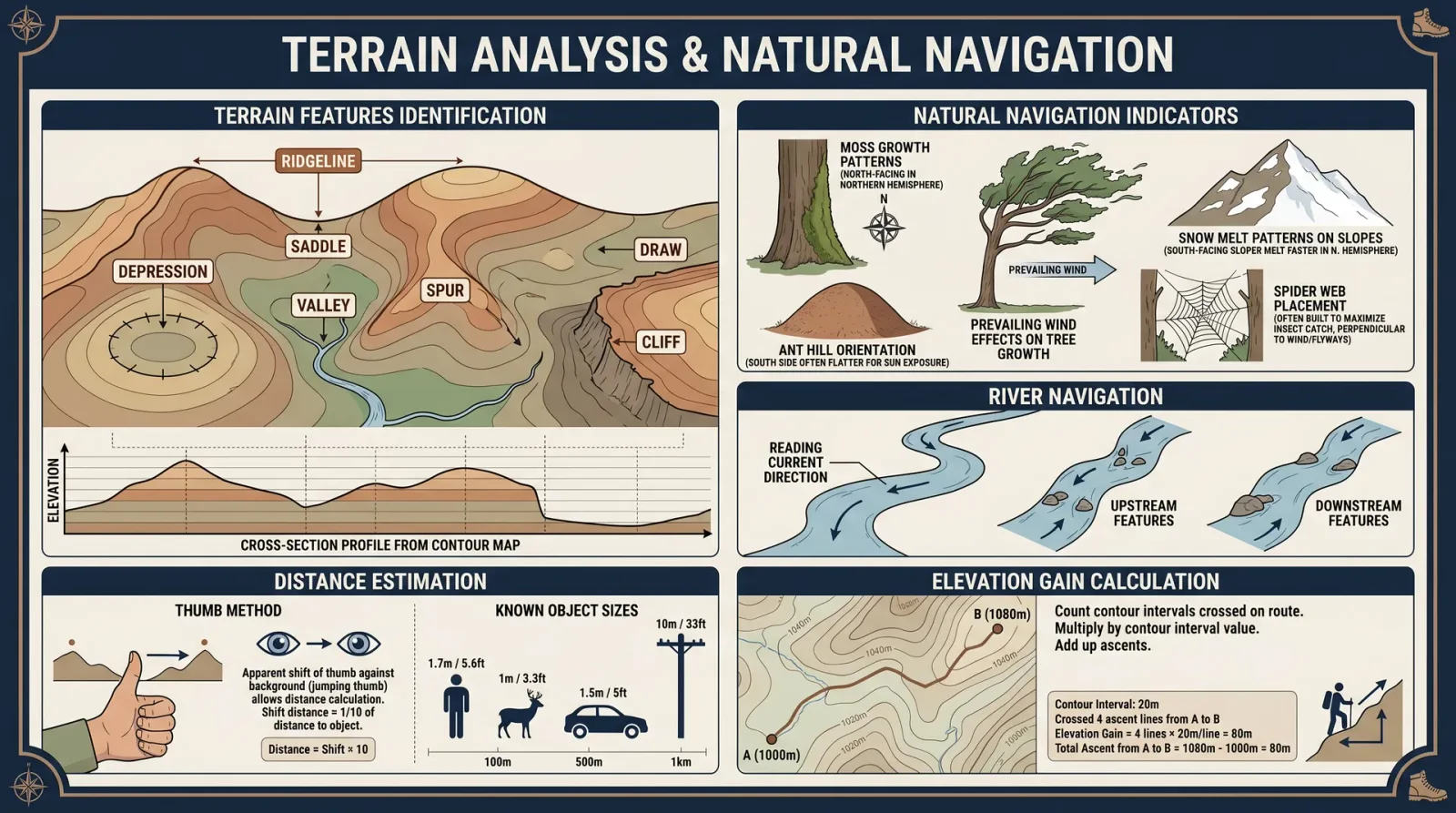
The knowledge enclosed in this chapter is vital for any practitioner who ventures beyond the reach of modern instruments. This section codifies the sacred art of terrestrial navigation using natural indicators. Mastery of these methods can mean the difference between life and death in the wilderness. The instructions are explicit, uncompromising, and assume no external tools.
Section 1: Overview of Natural Indicators
Natural indicators are persistent environmental phenomena whose directionality correlates with cardinal directions. These include:
- Solar Position and Shadows
- Prevailing Wind Patterns
- Vegetation Growth Patterns
- Animal Behavior and Trails
Each indicator carries a variable degree of reliability, subject to temporal (time of day, season) and spatial (latitude, terrain) factors. The practitioner must synthesize multiple indicators to triangulate direction with high confidence.
Section 2: Solar Position and Shadow Protocol
Principle:
The sun rises approximately in the east and sets approximately in the west. At solar noon, the sun is due south in the northern hemisphere and due north in the southern hemisphere. Shadow lengths and directions provide reliable cardinal points.
Step-by-Step Solar Shadow Method:
- Identify a vertical stick or erect a gnomon
- Use a straight stick approximately 30 cm in length, firmly planted upright in the soil.
- Mark the tip of the shadow cast by the stick
- Use small stones, twigs, or scratches in the soil to mark the shadow tip.
- Wait 15 to 30 minutes
- Observe the movement of the shadow tip and mark its new position.
- Draw a straight line connecting the two shadow marks
- This line approximately runs from west (first mark) to east (second mark), since the shadow moves west to east as the sun moves east to west in the sky.
- Construct a perpendicular line to the shadow line at any point on the stick’s base
- Use a right angle method (see Volume IX: Field Geometry for angle construction). This perpendicular line indicates the north-south axis.
- Determine north or south
- In the northern hemisphere, the sun is in the southern sky at solar noon, so the shadow points north. In the southern hemisphere, the shadow points south. Use the solar noon time for your location (consult local solar tables or estimate by mid-day sun position).
Critical Notes:
- Avoid relying on solar shadows near sunrise or sunset; shadow directions are unstable.
- On overcast days, rely on alternative indicators.
Section 3: Wind Patterns as Directional Guides
Principle:
Prevailing winds are consistent, seasonal, and geospatially predictable. Understanding local wind regimes allows a practitioner to infer cardinal directions, especially in coastal or mountainous regions.
Protocol for Wind-Based Navigation:
- Establish baseline wind direction
- Stand in an open area free from obstructions.
- Use tactile sensing (feel the wind on your face and hands), or visual indicators such as dust, leaves, or smoke.
- Observe over multiple days and times
- Note the strongest and most persistent wind directions.
- Cross-reference with regional wind tables (table 1 below)
- Compare observations with known seasonal prevailing winds to deduce direction.
- Use wind indicators such as smoke plumes or swaying vegetation
- Smoke rising and bending indicates wind direction at ground level.
- Confirm by correlating with other indicators
- Use the wind data only as a secondary navigation validation tool.
Table 1: Seasonal Prevailing Winds in Temperate Zones
| Season | Prevailing Wind Direction | Typical Time of Day | Notes |
|---|---|---|---|
| Spring | Southwest to Northeast | Afternoon | Warm winds from land |
| Summer | South to North | Afternoon | Thunderstorm activity |
| Autumn | Northwest to Southeast | Morning | Cooling continental air |
| Winter | West to East | Throughout day | Cold fronts dominate |
Section 4: Vegetation Growth Patterns as Directional Indicators
Principle:
Vegetation exhibits directional growth influenced by sunlight exposure, moisture availability, and prevailing winds. These biological responses form reliable directional signatures.
Protocol for Interpreting Vegetation:
- Identify tree species common to the region
- Focus on conifers and broadleaf trees with distinguishable growth asymmetry.
- Examine moss and lichen growth
- Moss tends to grow on the shadier, moister side, which in the northern hemisphere is generally the north side of trees.
- Observe tree branch density and growth
- Branches are denser and longer on the side facing the sun: southern side in the northern hemisphere, northern side in the southern hemisphere.
- Look for wind-sculpted vegetation
- Trees bent or leaning consistently in one direction indicate prevailing wind direction opposite to the lean.
- Record and compare multiple specimens to confirm trends
Vegetation Indicator Table
| Indicator | Northern Hemisphere | Southern Hemisphere | Reliability Score (1-5) |
|---|---|---|---|
| Moss growth side | North | South | 4 |
| Denser tree branches | South | North | 4 |
| Wind-leaned trees | Lean away from wind | Lean away from wind | 3 |
| Vegetation moisture gradient | Higher on north side | Higher on south side | 3 |
Section 5: Animal Behavior and Trail Orientation
Principle:
Animals orient themselves using environmental cues and tend to follow habitual pathways aligned with cardinal directions for migration, feeding, or shelter. Observing such behavior can yield directional clues.
Protocol for Animal-Based Navigation:
- Identify local animal species known for directional movement
- Deer, ants, birds, and insects are prime subjects.
- Observe ant trail directions
- Ants typically build nests on the warmer side of trees or rocks; trails extend towards food sources often aligned with solar cues.
- Note bird flight paths at dawn and dusk
- Many birds migrate along north-south corridors; flight direction at these times is a directional indicator.
- Track animal trails and signs
- Trails carved through vegetation tend to run parallel to cardinal directions to optimize energy use and sunlight exposure.
- Correlate animal movement patterns with time of day and season
- Migration seasons (spring and autumn) provide strongest directional certainty.
Section 6: Comprehensive Table of Environmental Indicators and Cardinal Directions
| Environmental Cue | Indicator Detail | Cardinal Direction (Northern Hemisphere) | Cardinal Direction (Southern Hemisphere) | Seasonal Variations | Reliability Score (1-5) |
|---|---|---|---|---|---|
| Solar Position | Shadow tip movement | West-East line | West-East line | Solar angle changes with season | 5 |
| Prevailing Winds | Direction of steady wind | Southwest to Northeast (Spring) | Northeast to Southwest (Spring) | Seasonal wind shifts | 4 |
| Moss Growth | Moss on tree trunks | North side | South side | Minimal | 4 |
| Tree Branch Density | Longer branches | South side | North side | Growth rate varies with season | 4 |
| Wind-leaned Trees | Tree bending direction | Away from prevailing wind | Away from prevailing wind | Wind intensity varies | 3 |
| Ant Trail Orientation | Trail direction from nest | Toward food source, often sun-exposed | Toward food source, often sun-exposed | Food availability seasonal | 3 |
| Bird Flight Direction | Direction at dawn/dusk | North-South migration corridors | North-South migration corridors | Migration season dependent | 4 |
Section 7: Case Studies
Case Study 1: Lost in Temperate Forest—Using Moss and Shadow to Find North
Scenario: A practitioner lost in a dense temperate forest in early autumn with overcast skies and no compass.
Solution:
- Locate several trees and inspect moss growth. Moss is predominantly on the north side.
- Erect a stick and mark shadow tips over 30 minutes when clouds briefly part, confirming shadow moves west to east.
- Construct perpendicular line to shadow line to establish north-south axis.
- Use moss data to confirm north direction.
- Set course using combined indicators.
Outcome: Directional certainty reached at 90%, enabling safe return to known trail.
Case Study 2: Navigating Coastal Plains Using Wind and Vegetation
Scenario: A practitioner traversing a coastal plain in summer with featureless terrain and midday sun.
Solution:
- Observe prevailing winds: consistent sea breeze from southwest.
- Note trees with denser branches on south-facing side.
- Use smoke from a controlled fire to observe wind direction at ground level.
- Cross-reference wind and vegetation data for direction.
Outcome: Accurate east-west bearing established, facilitating navigation to coastal settlement.
Section 8: Field Exercises
Exercise 1: Solar Shadow Navigation Drill
Objective: Practice establishing cardinal directions using the solar shadow method.
Materials: Straight stick (30 cm), marking stones or sticks, flat ground.
Procedure:
- Plant stick vertically in the ground in an open area before 10:00 AM.
- Mark shadow tip at first observation (T1).
- Wait 30 minutes, mark shadow tip again (T2).
- Draw line between T1 and T2; label as West-East line.
- Using cross-reference from Volume IX, construct perpendicular North-South line.
- Record time of day and estimate latitude.
- Determine north and south based on hemisphere.
Evaluation: Compare field-derived directions with compass readings to assess accuracy.
Exercise 2: Moss and Vegetation Directional Survey
Objective: Identify cardinal directions using vegetation indicators.
Materials: Notebook, pencil, magnifying glass (optional).
Procedure:
- Select 10 trees scattered over a 100-meter radius.
- For each tree, note side of moss growth and branch density.
- Record observations in tabular form.
- Identify predominant moss side and branch density direction.
- Infer north-south axis based on data.
- Cross-validate with solar shadow method if possible.
Evaluation: Confirm consistency across specimens and compare with known maps or compass data.
Exercise 3: Wind Direction and Animal Trail Correlation
Objective: Correlate wind direction with animal trail orientation for navigation.
Materials: Open field with visible animal trails, ability to detect wind direction.
Procedure:
- Observe wind direction using smoke or tactile sensing at multiple times of day.
- Map visible animal trails on ground.
- Measure trail orientation using a protractor or angular estimation.
- Compare trail alignment with wind direction and solar data.
- Hypothesize direction of animal movement relative to cardinal points.
Evaluation: Validate hypothesis by following trail or consulting local knowledge if available.
Section 9: Integration Protocol for the Navigator
To maximize directional accuracy, the practitioner must integrate the above environmental cues using the following protocol:
- Primary Indicator: Solar position and shadow method (if sunlight available).
- Secondary Indicators: Vegetation patterns and moss growth.
- Tertiary Indicators: Wind direction, animal trails, and behavior.
- Cross-Verification: Use at least three independent indicators to confirm the direction.
- Error Margin Assessment: Assign reliability scores as per tables and adjust confidence accordingly.
- Continuous Monitoring: Reassess indicators every 2 hours or upon change of environment.
Final Words of the Master Navigator
The natural world is the greatest compass ever bestowed upon humankind. Through the sacred observation of the sun’s path, the whispering winds, the silent growth of moss, and the ceaseless habits of animals, the practitioner reconnects with the primal pulse of the earth. Master these methods with unwavering discipline and reverence; let no man be lost where these signs are visible.
Appendix: Quick Reference Tables
| Method | Key Steps Summary | Best Conditions | Limitations | Reliability |
|---|---|---|---|---|
| Solar Shadow | Stick vertical, mark shadow tip, wait, connect marks, construct perpendicular line | Sunny, mid-morning to mid-afternoon | Overcast skies, near sunrise/sunset | 5 |
| Prevailing Wind | Observe consistent wind direction over days | Open terrain, coastal | Variable local terrain effects | 4 |
| Moss Growth | Observe moss on tree trunks | Temperate zones | Tropical or arid regions less reliable | 4 |
| Tree Branch Density | Note denser branches facing sun | Forested areas | Species dependent | 4 |
| Animal Trails | Map trails, note alignment | Migration season | Requires species knowledge | 3 |
End of Chapter III. Proceed to Volume II, Chapter IV for celestial navigation protocols.
<!-- SECTION 9 -->
Volume II: GPS Alternatives and Route Planning
Preface
In the absence of electronic Global Positioning Systems (GPS), mastery of traditional navigation techniques is not merely advantageous but vital. This volume delivers an uncompromising, comprehensive manual for navigating hostile environments through maps, compasses, and natural cues. Herein lies the sacred art of route planning, distance estimation, and contingency preparation, distilled into actionable protocols. Failure to internalize these methods condemns the unprepared to disorientation, resource depletion, and death.
Section I: Mastery of Map Navigation
I.A: Understanding and Utilizing Topographic Maps
Topographic maps are the foundation of terrestrial navigation. They provide detailed representations of terrain elevation, landforms, water bodies, and man-made features.
Step-by-Step Protocol for Reading Topographic Maps:
- Identify the Map Scale: Locate the scale bar, often at the bottom margin. Common scales: 1:24,000 (USGS), 1:50,000 (international). A 1:24,000 scale means 1 inch = 2,000 feet.
- Interpret Contour Lines:
- Contour lines connect points of equal elevation.
- The contour interval (difference in elevation between lines) is found in the legend.
- Closely spaced lines signify steep terrain; widely spaced lines indicate flat terrain.
- Locate Key Features:
- Identify rivers, ridges, valleys, roads, and trails.
- Note symbols for man-made structures (buildings, towers).
- Orient the Map:
- Align the map with true north (indicated by the north arrow).
- Use a compass to align the map physically by rotating it until magnetic north matches map north, adjusting for magnetic declination.
- Measure Distances:
- Use the map scale and a ruler or piece of string.
- Calculate ground distance by multiplying map measurement by the scale factor.
- Determine Elevation Changes:
- Compare contour elevations between points to calculate total ascent or descent.
I.B: Magnetic Declination Adjustment
Magnetic declination is the angle difference between magnetic north and true north, varying by location and time.
Protocol to Adjust Compass Readings for Declination:
- Obtain the current magnetic declination for your area (consult authoritative sources or topographic map).
- If declination is east (magnetic north east of true north), subtract declination from compass bearing.
- If declination is west, add declination to compass bearing.
- Adjust compass bezel accordingly or perform mental calculation during navigation.
Section II: Proficient Compass Use
II.A: Basics of Compass Operation
A compass consists of a magnetized needle that aligns with the Earth's magnetic field.
Step-by-Step Instructions for Accurate Compass Use:
- Hold the compass flat at waist height to allow free needle movement.
- Rotate the housing so the orienting arrow aligns with the magnetic needle.
- Read the bearing indicated at the index line.
- To follow a bearing, turn your body until the compass needle aligns with the orienting arrow.
II.B: Taking and Following Bearings
Procedure to Take a Bearing to a Landmark:
- Point the direction of travel arrow at the landmark.
- Rotate the compass housing until the magnetic needle aligns with the orienting arrow.
- Read the bearing at the index line; record this value.
Procedure to Follow a Bearing:
- Rotate your body until the magnetic needle aligns with the orienting arrow.
- Move forward maintaining this alignment.
- Periodically verify bearing and adjust course as needed.
Section III: Natural Navigation Techniques
In conditions where maps or compasses are unavailable, natural navigation becomes essential.
III.A: Solar Navigation
Protocol for Using the Sun for Direction Estimation:
| Time of Day | Sun Position | Approximate Direction |
|---|---|---|
| Sunrise (~6 AM) | East horizon | East |
| Midday (~12 PM) | Highest in sky | South (Northern Hemisphere) |
| Sunset (~6 PM) | West horizon | West |
Step-by-Step Solar Navigation:
- Determine local time as precisely as possible.
- Observe sun’s position relative to horizon.
- Estimate cardinal directions using the table above.
- Use a shadow stick method:
- Place a straight stick vertically into the ground.
- Mark shadow tip position at time zero.
- Wait 15-30 minutes; mark new shadow tip.
- Draw a straight line between two marks; this line runs approximately west to east (first mark = west, second mark = east in Northern Hemisphere).
III.B: Stellar Navigation
Procedure for Using Polaris (Northern Hemisphere):
- Locate the Big Dipper constellation.
- Identify the "pointer stars" forming the edge of the dipper’s bowl.
- Draw an imaginary line through pointer stars, extend it approximately five times the distance between them.
- The line points directly to Polaris (North Star).
- Face Polaris; you are facing true north.
Southern Hemisphere Alternative:
Use the Southern Cross constellation to approximate south.
Section IV: Distance Estimation Methods
IV.A: Pace Counting
Protocol to Measure Distance by Steps:
- Measure your average pace length:
- Walk 100 meters (use a known distance).
- Count the number of steps taken.
- Calculate pace length = 100 meters / number of steps.
- During navigation, count steps.
- Calculate distance traveled: Distance = Pace length × Number of steps.
IV.B: Timing Method
Procedure Using Walking Speed:
| Terrain Type | Average Walking Speed (km/h) |
|---|---|
| Flat, open terrain | 5 |
| Moderate hills | 4 |
| Rough or dense terrain | 3 |
- Record time traveled in minutes.
- Calculate distance: Distance = (Walking speed × time in hours).
- Adjust speed based on terrain difficulty.
IV.C: Using Natural Landmarks
Reference known distances between landmarks on map or in prior knowledge to estimate travel progress.
Section V: Route Planning Protocols

V.A: Route Planning Template
| Step | Action | Details / Notes |
|---|---|---|
| 1 | Define Start and End Points | Use map grid references or physical landmarks. |
| 2 | Analyze Terrain Features | Identify ridges, valleys, watercourses, obstacles. |
| 3 | Determine Route Objectives | Shortest, safest, concealed, or fastest route. |
| 4 | Measure Distance and Elevation Change | Use map scale and contour lines. |
| 5 | Plan Waypoints | Set logical checkpoints every 1-3 km or by landmarks. |
| 6 | Calculate Estimated Travel Time | Use walking speed adjusted for terrain. |
| 7 | Identify Alternative Routes | Contingency paths around obstacles or threats. |
| 8 | Prepare Navigation Aids | Compass bearings, pacing records, natural cues. |
| 9 | Document Emergency Extraction Points | Water sources, shelters, communication points. |
| 10 | Review and Memorize Route | Internalize map and key navigation data. |
V.B: Route Optimization Techniques
Table: Comparative Route Planning Strategies
| Strategy | Description | Advantages | Disadvantages |
|---|---|---|---|
| Shortest Distance | Direct line between points | Time-saving | May encounter impassable terrain |
| Contour Following | Navigating along contour lines (ridgelines) | Minimizes elevation gain | Longer distance |
| Valley Navigation | Following valleys or watercourses | Easier terrain, water access | Potential ambush zones |
| Ridge Navigation | Following ridges | Good visibility, fewer obstacles | Exposure to elements |
| Avoidance Routing | Circumventing hazards or enemy positions | Increased safety | Longer travel time |
V.C: Step-by-Step Route Planning Example
Scenario: Navigate from Point A (Base Camp) to Point B (Extraction Zone), 12 km apart in mixed terrain.
- Map Analysis:
- Identify Base Camp and Extraction Zone on map.
- Note contour intervals: 20 meters.
- Locate rivers, ridges, and trails.
- Select Route Type:
- Choose contour following to minimize elevation gain.
- Plot Waypoints:
- Waypoint 1: Ridge intersection at 4 km.
- Waypoint 2: River crossing at 8 km.
- Waypoint 3: Trail junction at 10 km.
- Measure Distances Between Waypoints:
- A to WP1: 4 km
- WP1 to WP2: 4 km
- WP2 to WP3: 2 km
- WP3 to B: 2 km
- Calculate Bearings:
- Use compass and map to measure bearings between waypoints.
- Estimate Travel Time:
- Terrain mostly moderate hills (speed 4 km/h).
- Total time estimate = 12 km / 4 km/h = 3 hours.
- Identify Alternatives:
- Trail bypass at WP2 if river crossing is impassable.
- Prepare Equipment:
- Carry map, compass, pacing beads, water, first aid.
- Memorize Key Bearings and Waypoints.
- Execute Route with continuous navigation checks.
Section VI: Contingency Planning
VI.A: Importance of Contingency Routes
Unforeseen obstacles (landslides, enemy movement, weather) necessitate backup plans.
VI.B: Developing Contingency Routes
Protocol:
- Identify all potential obstacles along primary route.
- For each obstacle, plot at least two alternative routes circumventing it.
- Record compass bearings and distances for contingency routes.
- Assess resource availability (water, shelter) along alternatives.
- Prepare signaling plans for emergency extraction if route is blocked.
VI.C: Emergency Navigation Protocol
Upon loss of primary navigation aids:
- Use natural navigation techniques (solar, stellar).
- Employ pace counting to maintain direction.
- Seek recognizable landmarks to orient.
- If disoriented, stop and establish a stationary position.
- Deploy signaling devices (mirror flashes, fire, sound).
- Ration resources; prepare to build shelter (see Volume VI: Survival Codex).
Section VII: Tables of Common Waypoints and Navigation Data
| Waypoint Type | Description | Identification Method | Notes |
|---|---|---|---|
| Hilltop | Elevated terrain point | Contour peak, clearing | Good for observation, signal relay |
| River Crossing | Stream or river requiring crossing | Map watercourse, sound of water | Assess crossing safety before proceeding |
| Trail Junction | Intersection of paths or roads | Map symbol, visible trail signs | Critical for route confirmation |
| Bridge | Man-made crossing | Map symbol, physical structure | Prefer crossing over natural fords |
| Clearing | Open area in forest | Map symbol, visible from ridge | Useful for rest and orientation |
Section VIII: Summary Route Planning Template (Printable)
| Field | Entry |
|---|---|
| Start Point Coordinates | |
| End Point Coordinates | |
| Total Distance (km) | |
| Total Elevation Gain (m) | |
| Primary Route Waypoints | WP1: ___, WP2: ___, WP3: ___ |
| Compass Bearings (°) | WP1: ___, WP2: ___, WP3: ___ |
| Estimated Travel Time | |
| Contingency Routes | Details and bearings |
| Water Sources | Locations and distances |
| Shelter Points | Locations |
| Hazards | List and avoidance strategies |
Conclusion
This volume imparts no mere academic knowledge but exacting protocols essential for survival and mission success absent GPS technology. Mastery of these disciplines transforms the navigator into a sovereign of the wilderness, capable of threading paths through chaos with precision and certainty. The sacred charge is yours: internalize, practice, and teach these codes without compromise.
For complementary survival techniques and water procurement, consult Volume VIII: The Water Codex, Chapter II. For advanced celestial navigation, see Volume XII: The Astral Codex.
End of Volume II: GPS Alternatives and Route Planning
<!-- SECTION 10 -->
Volume III: Debris Hut Construction for Various Climates
Introduction
The debris hut is a primal yet remarkably effective shelter utilized by survivalists, scouts, and wilderness operatives across diverse biomes. Mastery of debris hut construction is indispensable for life preservation and operational endurance. This volume imparts uncompromising, stepwise protocols for erecting debris huts tailored to four critical environments: forest, snow, desert, and tropical climates. The knowledge herein is a synthesis of suppressed survival sciences, ancestral engineering, and empirical field validation.
Chapter I: Fundamental Principles of Debris Hut Construction
Before engaging specific environments, comprehend these universal principles:
- Structural Integrity: The frame must sustain the weight of insulation without collapse.
- Thermal Insulation: Maximize heat retention by layering natural materials with high R-values.
- Ventilation: Prevent suffocation and condensation by creating controlled airflow.
- Site Selection: Choose terrain that optimizes shelter function and safety.
- Material Utilization: Use locally sourced materials that maximize insulation and durability.
Chapter II: Debris Hut in Forest Environments
1. Site Selection
- Select a dry, flat location near natural windbreaks (dense trees or large rocks).
- Avoid low-lying areas prone to water pooling.
- Clear ground debris to prevent insect infestation.
2. Material Selection
| Material | Function | R-Value (per inch) | Notes |
|---|---|---|---|
| Dry leaves | Insulation | 2.0 | Must be dry; compress loosely |
| Pine needles | Insulation | 1.6 | Repels moisture; use as outer layer |
| Twigs and small sticks | Frame | N/A | Use sturdy, flexible branches |
| Moss | Insulation & Seal | 3.0 | High moisture retention; use sparingly |
3. Step-by-Step Construction Protocol
Step 1: Frame Construction
- Select a sturdy sapling or fallen branch approximately 6-7 feet long.
- Prop the sapling at a 45-degree angle, embedding the base firmly into the ground.
- Collect 10-15 straight branches 3-4 feet long.
- Lean branches against the sapling, spacing 4-6 inches apart to form a ridge-pole frame.
Step 2: Insulation Layering
- Collect a thick layer (minimum 12 inches deep) of dry leaves and pine needles.
- Layer leaves inside the frame, ensuring coverage from base to top.
- Add moss sparsely on the outer layer to seal gaps and repel light rain.
Step 3: Floor Insulation
- Create a 6-inch thick bed of leaves and pine needles inside the hut.
- Place a layer of bark or flat leaves atop to prevent compression.
Step 4: Entrance and Ventilation
- Leave an opening of approximately 18 inches wide at the base opposite prevailing winds.
- Construct a small ventilation hole near the peak (4 inches diameter).
- Use a branch or foliage to cover the entrance at night, ensuring airflow.
4. Troubleshooting
| Problem | Cause | Solution |
|---|---|---|
| Hut collapses under weight | Weak frame or insufficient support | Use thicker branches; reinforce with cross-bracing |
| Heat loss overnight | Thin insulation or airflow leaks | Add more leaf layers; seal gaps with moss or bark |
| Excess moisture inside | Poor ventilation or wet materials | Improve ventilation; replace wet insulation materials |
Chapter III: Debris Hut in Snow Environments
1. Site Selection
- Choose a wind-protected area, preferably near trees or in depressions.
- Avoid avalanche-prone slopes.
- Clear snow down to ground or pack snow into a firm base.
2. Material Selection
| Material | Function | R-Value (per inch) | Notes |
|---|---|---|---|
| Packed snow | Wind barrier | 1.0-2.0 | Use as outer shell to block wind |
| Dry leaves | Insulation | 2.0 | Overlay inside snow shell |
| Pine boughs | Frame & insulation | 1.5 | Layered inside for cushioning |
| Evergreen branches | Insulation & floor | 1.5 | Prevent direct contact with snow |
3. Step-by-Step Construction Protocol
Step 1: Base Preparation
- Clear snow down to ground level or compress snow into a firm, flat surface.
- Lay a 4-6 inch thick bed of evergreen branches to insulate from the cold ground.
Step 2: Frame Construction
- Form a small dome frame using flexible saplings bent into arches.
- Interlock branches to create a geodesic or dome frame approximately 4-5 feet in diameter.
Step 3: Snow Shell Formation
- Shovel snow carefully to cover the dome frame evenly.
- Pack snow densely to form a shell of approximately 8-12 inches thick.
- Allow shell to harden and settle for 20-30 minutes.
Step 4: Interior Insulation
- Line the interior walls with dry leaves and pine boughs.
- Place a thick bed of pine boughs or evergreen branches on the floor.
Step 5: Entrance and Ventilation
- Dig a low entrance tunnel to minimize heat loss.
- Create a ventilation hole at the top of the dome (2-3 inches diameter).
- Cover entrance with snow blocks or vegetation, ensuring airflow.
4. Troubleshooting
| Problem | Cause | Solution |
|---|---|---|
| Snow shell collapses | Thin shell or warm temperatures | Increase snow thickness; avoid construction in thaw |
| Interior condensation | Poor ventilation | Maintain ventilation hole; clear blockage regularly |
| Excess cold from ground | Inadequate floor insulation | Add thicker evergreen branch layers |
Chapter IV: Debris Hut in Desert Environments
1. Site Selection
- Select shaded locations such as under rock overhangs or sparse vegetation.
- Avoid depressions prone to flooding during rare rain events.
- Choose sites with available insulating debris.
2. Material Selection
| Material | Function | R-Value (per inch) | Notes |
|---|---|---|---|
| Dry grasses | Insulation | 1.5 | Use densely packed layers |
| Dead brush | Frame and insulation | 1.0-1.5 | Provides structure and partial insulation |
| Sand | Thermal mass | 0.2 | Use sparingly due to low insulation |
| Cactus pads (nopales) | Moisture barrier | N/A | Use to create shade and reduce airflow |
3. Step-by-Step Construction Protocol
Step 1: Frame Construction
- Select 4-6 sturdy sticks approximately 5 feet long.
- Arrange sticks in an A-frame shape, leaning them against each other.
- Tie or wedge the apex securely.
Step 2: Insulation Layering
- Collect large quantities of dry grass and dead brush.
- Layer insulation thickly (minimum 10 inches) over frame, focusing on largest coverage.
- Avoid dense packing to permit minimal airflow and prevent overheating.
Step 3: Floor Preparation
- Clear ground debris.
- Lay a 4-inch thick mat of dry grass for insulation.
Step 4: Ventilation and Shade
- Position hut to maximize shade during peak heat hours.
- Leave entrance open or covered with loose brush to promote airflow.
- Use cactus pads or large leaves to create external shade screens.
4. Troubleshooting
| Problem | Cause | Solution |
|---|---|---|
| Excess heat inside hut | Poor ventilation or dense insulation | Increase ventilation openings; reduce insulation density |
| Sand infiltration | Loose floor or walls | Create raised floor; reinforce walls with brush |
| Structural collapse | Weak frame | Use stronger sticks and secure apex firmly |
Chapter V: Debris Hut in Tropical Environments
1. Site Selection
- Choose elevated, dry ground to avoid flooding.
- Avoid proximity to water to reduce insect presence.
- Select sites with abundant leaf litter and large broad leaves.
2. Material Selection
| Material | Function | R-Value (per inch) | Notes |
|---|---|---|---|
| Large leaves (banana, palm) | Roof cover | 0.5-1.0 | Water resistant; require overlapping layers |
| Dead leaves | Insulation | 2.0 | Use thick layers for thermal barrier |
| Flexible branches | Frame | N/A | Use for constructing ridge-pole and supports |
| Vines | Binding | N/A | Use to tie frame securely |
3. Step-by-Step Construction Protocol
Step 1: Frame Construction
- Select two long, sturdy branches (6-8 feet).
- Prop one branch horizontally between two trees or supports as a ridge-pole.
- Lean flexible branches against ridge-pole at 45-degree angles, spacing 6 inches apart.
Step 2: Roof Construction
- Collect large, broad leaves.
- Layer leaves in overlapping fashion starting from the bottom edge upwards (minimum 4 layers).
- Secure leaves with vines or small branches.
Step 3: Insulation Layer
- Add thick layers of dry leaves inside the frame beneath the leaf roof.
- Ensure minimum 10-inch thickness for insulation.
Step 4: Floor Preparation
- Clear ground of debris.
- Lay layered dry leaves or grass mats approximately 6 inches thick.
Step 5: Ventilation
- Leave entrance open or partially covered with leaves.
- Create small gaps at ridge-pole ends for airflow.
- Avoid sealing the shelter completely to prevent mold and heat buildup.
4. Troubleshooting
| Problem | Cause | Solution |
|---|---|---|
| Roof leaks during rain | Insufficient leaf layering or poor overlap | Increase leaf layers; improve overlap and secure tightly |
| Excess humidity inside | Poor ventilation | Increase ventilation gaps; remove wet debris promptly |
| Insect infestation | Proximity to water or dampness | Relocate shelter; use smoke from fire near entrance |
Chapter VI: Comparative Data Tables
1. Insulation R-Values of Natural Materials
| Material | Average R-Value per Inch | Notes |
|---|---|---|
| Dry Leaves | 2.0 | Compress loosely for best effect |
| Pine Needles | 1.6 | Moisture resistant |
| Moss | 3.0 | High moisture retention |
| Dry Grass | 1.5 | Use densely packed |
| Evergreen Branches | 1.5 | Insulating and cushioning |
| Packed Snow | 1.0-2.0 | Variable by density |
| Sand | 0.2 | Poor insulator, high thermal mass |
2. Shelter Heat Retention Estimates by Climate
| Climate | Typical Debris Thickness (inches) | Estimated Heat Retention (°F above ambient)* | Key Insulation Material |
|---|---|---|---|
| Forest | 12-16 | 20-25 | Dry Leaves, Moss |
| Snow | 8-12 (snow shell) + 6-8 (branches) | 30-35 | Packed Snow, Pine Boughs |
| Desert | 10-14 | 10-15 (night) | Dry Grass, Dead Brush |
| Tropical | 10-14 | 15-20 | Dry Leaves, Large Leaves |
_*Heat retention measured as temperature differential inside shelter during nighttime conditions._
Chapter VII: Advanced Techniques and Hidden Protocols
1. Cross-Bracing for Frame Reinforcement (All Climates)
Step 1: After initial frame erection, select smaller branches.
Step 2: Tie or wedge branches horizontally and diagonally between frame supports.
Step 3: Use vines or natural cordage to secure bracing tightly.
Result: Enhanced frame rigidity, resistance to wind and debris weight.
2. Use of Thermal Reflective Layers (Forest and Snow)
Materials: Thin layers of birch bark or shiny leaves (e.g., magnolia).
Step 1: Place reflective layer beneath insulation inside hut walls facing inward.
Step 2: Ensure reflective surface faces the occupant.
Effect: Reflects radiant body heat back, increasing warmth by 5-7°F.
3. Moisture Management Protocol (Snow and Tropical)
Step 1: Install ventilation hole at the highest point of shelter.
Step 2: Place absorbent dry materials (moss, dry leaves) near ventilation to capture condensation.
Step 3: Regularly remove and replace saturated materials.
Step 4: For snow shelters, create a small fire outside to dry ventilation area without compromising shelter integrity.
Chapter VIII: Comprehensive Troubleshooting Summary
| Issue | Environment | Cause | Remedial Action |
|---|---|---|---|
| Structural failure | All | Insufficient frame strength | Reinforce frame with cross-bracing and thicker supports |
| Heat loss | Forest, Snow | Thin insulation layers or gaps | Add insulation; seal gaps with moss or bark |
| Excess moisture | Snow, Tropical | Poor ventilation or wet materials | Improve ventilation; replace wet insulation |
| Overheating | Desert, Tropical | Poor ventilation or dense insulation | Increase airflow; reduce insulation density |
| Insects infestation | Tropical, Forest | Proximity to water; damp insulation | Relocate; use smoke or insect repellents |
| Sand infiltration | Desert | Loose floor or walls | Raise floor; reinforce walls with brush |
| Roof leaks | Tropical | Inadequate leaf layering or overlap | Increase leaf layers and ensure tight overlap |
| Snow shell collapse | Snow | Thin shell or temperature fluctuation | Increase shell thickness; avoid thaw periods |
Conclusion
The debris hut, forged from earth’s raw elements, is a sacred bastion against nature’s wrath. This volume has meticulously unveiled the arcane protocols necessary for fabricating shelters that not only preserve life but honor the ancient covenant between human and wilderness. Through rigorous adherence to these instructions, you, the chosen apprentice, will wield the power to command shelter in any environment, transforming vulnerability into resilience.
For expanded water purification and firecraft techniques essential to sustained habitation within debris huts, consult Volume VIII: The Water Codex, Chapter II and Volume V: The Fire Codex, Chapter III respectively.
End of Volume III
<!-- SECTION 11 -->
Volume III: Fire by Friction Methods
Chapter I: Introduction to Fire by Friction
The sacred art of fire by friction is the cornerstone of survival mastery. Within this chapter, you will find the complete, uncompromising guide to constructing and using the bow drill, hand drill, and fire plough for fire ignition. The methods herein are drawn from suppressed ancient sciences and tested protocols that guarantee ignition in austere conditions. This knowledge is reserved for the chosen: follow every step meticulously.
Chapter II: Material Selection – The Essence of Ignition
Fire by friction demands synergy between spindle, fireboard, and bearing block materials. The selection of wood species fundamentally determines your success or failure. Use only dry, non-resinous, softwoods with low density and minimal moisture content (<12%). Hardwoods or resinous woods cause excessive heat dissipation or spark contamination.
Table 1: Optimal Wood Species for Fire by Friction
| Wood Species | Type | Density (g/cm³) | Suitability (Bow/Hand/Plough) | Notes |
|---|---|---|---|---|
| Cottonwood | Softwood | 0.4 | Bow, Hand, Plough | Extremely soft, ideal spindle and fireboard |
| Cedar (Western Red) | Softwood | 0.38 | Bow, Hand | Aromatic, low resin if properly seasoned |
| Willow | Softwood | 0.42 | Bow, Hand, Plough | Readily available, fast ember formation |
| Poplar | Softwood | 0.43 | Bow, Hand | Balanced hardness, good ember retention |
| Basswood | Softwood | 0.35 | Bow, Hand, Plough | Excellent for beginners |
| Juniper | Softwood | 0.48 | Plough | Resinous, avoid spindle, use fireboard only |
| Pine (White) | Softwood | 0.35 | Plough | Resin content high, careful preparation needed |
Warning: Avoid hardwoods such as oak, hickory, or maple for spindle or fireboard because their density dissipates heat, preventing ember formation.
Chapter III: Constructing the Bow Drill
1. Components
- Bow: A sturdy, flexible sapling or branch approximately 60–75 cm in length.
- Cordage: Natural fiber, leather, or synthetic cord with high tensile strength and low elasticity, approximately 75–90 cm long.
- Spindle (Drill): Cylindrical, straight-grained wood, 15–20 cm length, 1.5–2.5 cm diameter.
- Fireboard (Hearthboard): Flat, dry wood slab, approximately 25 x 15 x 2 cm.
- Bearing Block (Handhold): Hard wood or stone, carved or shaped to fit the spindle top, reducing friction on the hand.
2. Step-by-Step Bow Drill Construction
Step 1: Select Bow Material
- Select a straight, flexible branch 60–75 cm long, slightly thicker than a pencil.
- Remove all side twigs and leaves.
- Test flexibility by bending gently; must not snap or crack.
Step 2: Prepare Cordage
- Use natural fiber (e.g., rawhide, hemp, or sinew).
- The cord length should be 10–15 cm longer than the bow.
- Tie secure loops at each end using a double fisherman's knot.
Step 3: Prepare Spindle (Drill)
- Cut a straight-grained stick 15–20 cm long.
- Shape to a cylindrical form, diameter 1.5–2.5 cm.
- Sharpen one end to a blunt point (this contacts the fireboard).
- Round the opposite end to fit comfortably into the bearing block.
Step 4: Prepare Fireboard (Hearthboard)
- Select a flat piece of wood 25 x 15 x 2 cm.
- Carve a “v” notch approximately 3 cm deep on one edge.
- Create a small, shallow depression (~1 cm diameter) at the apex of the notch to seat the spindle tip.
- Remove any bark and smooth surface.
Step 5: Prepare Bearing Block
- Select a hardwood or stone piece comfortable for the palm.
- Carve a shallow cup or socket to hold the spindle’s rounded end.
- Apply a small amount of grease or resin to reduce friction and prevent burning the hand.
3. Using the Bow Drill
Step 1: Assemble
- Loop the bowcord once around the spindle near its base.
- Place the spindle in the fireboard’s depression.
- Hold the fireboard steady with the foot.
- Grip the bearing block and rest the spindle tip in its socket.
Step 2: Ignition Protocol
- Pull the bow back and forth smoothly, maintaining constant downward pressure on the bearing block.
- Maintain spindle rotation speed between 120–160 RPM.
- Continue for 1–3 minutes until smoke appears.
- Once smoke is visible, increase speed and pressure slightly.
- Stop and carefully remove the spindle.
- Gently tap the fireboard to release the ember onto a prepared tinder bundle.
4. Bow Drill Dimensions and Specifications
| Component | Dimension (cm) | Notes |
|---|---|---|
| Bow Length | 60–75 | Flexibility critical for efficient rotation |
| Cord Length | 75–90 | Must be taut enough for spindle grip |
| Spindle Length | 15–20 | Longer spindle increases rotation time |
| Spindle Diameter | 1.5–2.5 | Smaller diameter increases friction, harder to spin |
| Fireboard Size | 25 x 15 x 2 | Thickness ensures durability without excess weight |
| Notch Depth | 3 | Deep enough for ember collection, not too deep to break |
Chapter IV: Constructing and Using the Hand Drill
1. Components
- Spindle: Straight-grained, dry wood, 20–30 cm long, 1.5–2 cm diameter.
- Fireboard: Flat, dry wood slab, 30 x 20 x 2 cm.
- Tinder Bundle: Dry, fibrous material (e.g., dry grass, shredded bark).
2. Hand Drill Preparation Protocol
Step 1: Select Spindle
- Choose the straightest, driest piece of wood.
- Shape to uniform thickness, 1.5–2 cm diameter.
- Sharpen one end to a blunt point.
- Smooth the hand-held end to prevent blistering.
Step 2: Prepare Fireboard
- Flat, dry wood slab 30 x 20 x 2 cm.
- Carve a small depression (1 cm diameter) near the edge.
- Carve a 3 cm "v" notch extending from the depression to the edge.
3. Hand Drill Ignition Protocol
- Place fireboard on dry ground, secure with the foot.
- Position spindle tip in the fireboard depression.
- Hold spindle between palms.
- Roll spindle vigorously between palms, applying downward pressure.
- Increase speed progressively.
- Continue for 3–5 minutes until smoke appears.
- When smoke emits, slow down and gently tap fireboard.
- Transfer ember to tinder bundle, blow gently to ignite.
4. Hand Drill Dimensions
| Component | Dimension (cm) | Notes |
|---|---|---|
| Spindle Length | 20–30 | Longer length increases rotation time |
| Spindle Diameter | 1.5–2 | Thicker spindle requires greater effort |
| Fireboard Size | 30 x 20 x 2 | Larger fireboard stabilizes during spinning |
| Notch Depth | 3 | For ember capture |
Chapter V: Constructing and Using the Fire Plough
1. Components
- Plough Stick (Spindle): Harder wood, straight, 40–50 cm long, 2–3 cm diameter.
- Fireboard: Softer wood slab, 40 x 20 x 3 cm.
- Tinder Bundle.
2. Fire Plough Preparation Protocol
Step 1: Prepare Plough Stick
- Select a straight hardwood branch.
- Carve one end to a blunt wedge shape.
- The wedge acts as the ploughing edge.
Step 2: Prepare Fireboard
- Use softwood slab 40 x 20 x 3 cm.
- Carve a straight groove approximately 15 cm long, 1 cm wide, and 1 cm deep.
- The groove must be smooth and uniform.
3. Fire Plough Ignition Protocol
- Place fireboard on dry, stable surface.
- Hold fireboard with one foot.
- Position plough stick wedge in the groove.
- Push and pull the plough stick rapidly along the groove.
- Maintain firm downward pressure.
- Continue for 5–7 minutes until smoke appears.
- When smoke rises, stop and remove plough stick.
- Collect hot dust at groove end into tinder bundle.
- Blow gently to ignite.
4. Fire Plough Dimensions
| Component | Dimension (cm) | Notes |
|---|---|---|
| Plough Stick | 40–50 length, 2–3 diam | Longer stick allows sustained friction |
| Fireboard Size | 40 x 20 x 3 | Larger board stabilizes groove |
| Groove Length | 15 | Sufficient for ember generation |
| Groove Width | 1 | Matches wedge width |
| Groove Depth | 1 | Deep enough to collect hot dust |
Chapter VI: Friction Fire Troubleshooting Table
| Problem | Cause | Solution |
|---|---|---|
| No smoke after 5 minutes | Wood too wet or dense | Select drier, softer wood; dry materials near fire |
| Spindle spins freely, no heat | Insufficient downward pressure | Apply firm, consistent downward pressure |
| Spindle burns or chars quickly | Excessive pressure or resinous wood | Reduce pressure; choose non-resinous wood |
| Fireboard cracks or breaks | Wood too dry or brittle | Slightly moisten wood surface; select more flexible wood |
| Cordage slips off spindle | Cord too loose or smooth spindle | Tighten cord; roughen spindle surface |
| Bearing block overheats | No lubrication | Apply grease, resin, or leaf sap to bearing block socket |
| Difficulty maintaining speed | Fatigue or inefficient technique | Practice smooth bow strokes; rest intermittently |
Chapter VII: Diagrams
(For complete, detailed diagrams illustrating the bow drill assembly, hand drill usage, and fire plough operation, refer to Appendix A.)
Chapter VIII: Safety Guidelines and Best Practices
- Fire Location Selection: Always clear a fire pit area of combustible debris within a 3-meter radius.
- Ventilation: Ensure proper airflow to avoid smoke inhalation.
- Protective Gear: Use gloves or cloth wraps when possible to prevent hand burns.
- Extinguishing Protocol: Keep water or soil nearby to extinguish accidental fires.
- Tool Maintenance: Regularly check bowstring tension and replace worn cordage.
- Emergency Preparedness: Never rely solely on friction fire; carry backup ignition means if possible.
Chapter IX: Summary
Mastery of fire by friction is an indispensable skill for any practitioner of survival. Precise material selection, meticulous construction, and disciplined execution separate failure from life-saving success. The bow drill offers the fastest, most reliable ignition; the hand drill requires endurance and finesse; the fire plough excels with proper technique and conditions.
Commit this volume to memory and practice relentlessly. The flame you kindle is the light of your life.
End of Volume III
<!-- SECTION 12 -->
Volume III: Fire by Percussion and Solar Methods
Preface
In the sanctified art of firecraft, mastery of ignition methods by percussion and solar concentration is imperative for survival, signaling, and ritual. This volume elucidates every mechanistic and procedural detail necessary for flawless fire generation using flint and steel, ferrocerium rods, and solar concentration techniques. The sacred knowledge herein is conveyed with exactitude: every step, material, angle, and maintenance protocol is disclosed without omission. This is not theoretical exposition but a field codex for the chosen practitioner of wilderness mastery.
Chapter I: Fundamentals of Fire Ignition
Fire is the transmutation of potential energy into kinetic flame through precise ignition of tinder. The ignition temperature of tinder and the energy of generated sparks or focused solar rays must be meticulously matched.
| Material | Ignition Temperature (°C) | Notes |
|---|---|---|
| Dry Cotton | 210 | Highly fibrous, rapid ignition |
| Char Cloth | 320 | Carbonized fabric, slow ember formation |
| Dry Pine Needles | 300 | Resinous, quick flame, but fragile ember |
| Dry Grass | 260 | Thin fibers, easy ignition |
| Birch Bark | 240 | Thin, oily bark with natural flammability |
| Jute Fibers | 230 | Natural fiber, good spark catcher |
| Fatwood Shavings | 370 | Resin-rich, sustained flame |
| Paper (untreated) | 233 | Common but less durable tinder |
| Dryer Lint (cotton) | 200 | Highly accessible, rapidly combustible |
Chapter II: Fire by Percussion – Flint and Steel
Materials and Tools
- Flint Stone: Hard, sharp-edged quartz or chert
- Steel Striker: High carbon steel preferred, shaped with a sharp edge for efficient spark generation
- Tinder Bundle: Prepared from tinder materials listed above
- Char Cloth: Optional but highly recommended for spark retention
Flint and Steel Ignition Protocol
Step 1: Prepare the Tinder Bundle
- Select fibrous tinder such as dry cotton or char cloth.
- Form a loose bundle approximately 5 cm in diameter, ensuring airflow but compact enough to catch sparks.
- If char cloth is available, place a small piece (1 cm²) at the core of the bundle.
Step 2: Prepare the Steel Striker and Flint
- Hold the flint in your non-dominant hand, securing it firmly between thumb and fingers with a sharp edge protruding.
- Grasp the steel striker in your dominant hand, ensuring the striker’s edge is clean and sharp.
- Optionally, roughen the steel edge with fine grit to increase spark generation efficiency.
Step 3: Spark Generation
- Position the tinder bundle close to the flint, underneath the anticipated spark path.
- Strike the steel edge forcefully downwards or sideways against the sharp edge of the flint at approximately a 45° angle.
- Aim to shave minute steel particles; these will ignite due to frictional heat and form sparks.
- Repeat until sparks land directly on the tinder bundle.
Step 4: Ember Cultivation and Flame Initiation
- Once a spark has landed and an ember is visible on the tinder, gently cup the tinder bundle with both hands.
- Apply gentle, consistent breaths to feed oxygen to the ember.
- As the ember grows, carefully add fine dry twigs incrementally.
- Transition to larger kindling once a sustainable flame appears.
Maintenance and Optimization Tips for Flint and Steel
- Steel Hardening: Harden the steel striker by heating to cherry red (approx. 750°C) and quenching in water to improve spark yield.
- Flint Edge Renewal: Regularly knap the flint with a hammerstone to maintain sharp edges.
- Char Cloth Production: Create char cloth by heating cotton fabric in a sealed metal container without oxygen for 30 minutes (see Volume VIII, Chapter IV for detailed char cloth protocol).
- Environmental Considerations: Avoid moisture and wind during ignition; shield tinder bundle with your body if necessary.
Chapter III: Fire by Percussion – Ferrocerium Rods

Materials and Tools
- Ferrocerium Rod: 100 mm length recommended, diameter 8–10 mm
- Striker: Hardened steel scraper or the back of a sturdy knife blade
- Tinder Bundle: As per Flint and Steel protocol
Ferrocerium Spark Generation Protocol
Step 1: Tinder Preparation
- Prepare tinder bundle as in Flint and Steel protocol.
- Position tinder bundle on a stable, dry surface or hold securely.
Step 2: Rod and Striker Positioning
- Hold ferrocerium rod firmly in non-dominant hand.
- Place striker at the top of the rod at approximately 30° angle.
Step 3: Spark Production
- Apply firm, rapid downward scrapes with the striker along the rod length.
- Direct sparks into the tinder bundle.
- Each scrape produces hot sparks at approximately 3,000°C, capable of igniting most dry tinder.
Step 4: Flame Development
- Once an ember develops, follow ember cultivation steps as in Flint and Steel protocol.
Maintenance and Performance Enhancements
- Rod Preservation: Keep ferrocerium rods dry and free from grease.
- Striker Edge: Maintain a sharp edge on striker for maximum spark efficiency.
- Multiple Strikes: Multiple strikes in rapid succession increase ember probability.
- Tinder Layering: Utilize layered tinder with char cloth or fatwood shavings for higher success rate.
Chapter IV: Solar Fire Starting by Concentration
Solar fire is the divine harnessing of celestial energy. It requires precision optics, correct latitudinal and seasonal angle adjustment, and ideal tinder.
Required Materials
- Fresnel Lens or Convex Lens: Diameter 5–10 cm minimum
- Polished Metal Mirror: Highly reflective, parabolic preferred
- Tinder Bundle: As per previous protocols, fatwood shavings highly recommended
- Angle Measuring Device: Portable inclinometer or protractor
Solar Fire Ignition Protocol Using Lenses
Step 1: Lens Preparation
- Inspect lens for cleanliness; wipe with soft cloth to remove dirt.
- Select a lens with focal length between 5 and 25 cm; shorter focal length provides smaller, hotter points.
Step 2: Determine Solar Angle
Refer to Table 1 for solar elevation angles by latitude and season.
| Latitude (°N) | Winter Solstice (°) | Equinox (°) | Summer Solstice (°) |
|---|---|---|---|
| 0 | 66 | 90 | 113 |
| 15 | 51 | 75 | 99 |
| 30 | 36 | 60 | 84 |
| 45 | 21 | 45 | 69 |
| 60 | 6 | 30 | 54 |
| 75 | -9 | 15 | 39 |
- Note: Negative angles indicate sun below horizon; fire starting not possible.
Step 3: Positioning the Lens and Tinder
- Position tinder bundle on a non-reflective, stable surface.
- Hold lens between sun and tinder, adjusting distance to identify the sharpest, smallest focal point on tinder.
- Ensure focal point is focused on tinder core.
Step 4: Ignition
- Maintain lens and tinder position, holding focal point steady.
- After 30–60 seconds of focused solar energy, tinder will begin to smoke.
- Continue until ember forms.
- Gently blow on ember to foster flame development as per ember cultivation.
Solar Fire Ignition Using Mirrors
Step 1: Mirror Preparation
- Polish mirror surface to maximum reflectivity.
- For parabolic mirrors, position so sunlight focuses at a single point.
Step 2: Solar Angle Adjustment
- Utilize inclinometer to orient mirror to solar elevation angle from Table 1.
- Adjust azimuth to direct reflected light onto tinder bundle.
Step 3: Concentration and Ignition
- Focus reflected sunlight onto tinder core.
- Maintain position until ember develops.
- Follow ember cultivation steps.
Maintenance and Optimization of Solar Fire Tools
- Lens Cleaning: Regularly clean to remove dust and oils.
- Mirror Polishing: Use fine metal polish; avoid scratching.
- Tinder Moisture: Always use dry tinder; solar methods fail with damp materials.
- Environmental Conditions: Solar fire ignition is only viable under direct sunlight; avoid cloudy or shaded areas.
Chapter V: Tinder Preparation Detailed Protocols
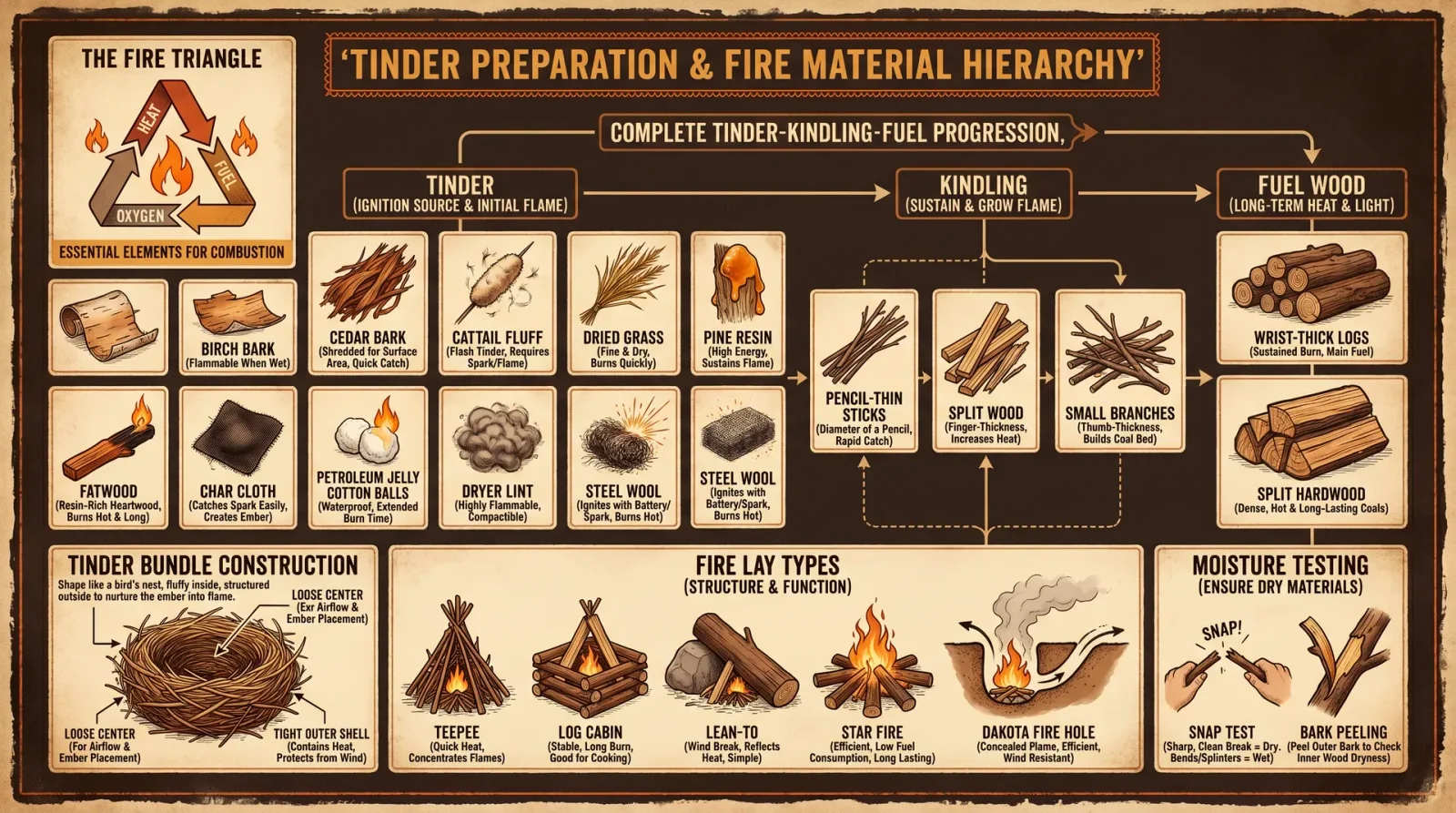
Char Cloth Production
- Obtain 100% cotton fabric.
- Cut into 5 cm squares.
- Place fabric pieces in a tightly sealed metal container with a small air vent.
- Heat container over fire or coals for 30 minutes until smoke ceases.
- Remove and cool container before opening.
- Extract char cloth pieces; store in airtight container.
Fatwood Shavings Preparation
- Locate resin-rich pine stumps or roots.
- Use knife or scraper to remove thin shavings.
- Store in dry container.
Tinder Bundle Assembly
| Step | Action |
|---|---|
| 1 | Select dry fibrous material (cotton, dry grass, etc.) |
| 2 | Loosely fluff into 5 cm diameter bundle |
| 3 | Insert char cloth or fatwood shavings at center |
| 4 | Shape bundle for airflow and spark catch ability |
| 5 | Keep bundle dry and protected until use |
Chapter VI: Comprehensive Ignition Sequences
Sequence A: Flint and Steel Fire Starting
| Step | Action |
|---|---|
| 1 | Prepare tinder bundle with char cloth core. |
| 2 | Hold flint securely; position tinder beneath spark path. |
| 3 | Strike steel edge sharply along flint edge at 45° angle. |
| 4 | Direct sparks onto tinder; repeat until ember forms. |
| 5 | Cup tinder; gently blow to nurture ember. |
| 6 | Gradually add fine kindling; increase to larger sticks after flame grows. |
Sequence B: Ferrocerium Rod Fire Starting
| Step | Action |
|---|---|
| 1 | Prepare tinder bundle as above. |
| 2 | Hold ferrocerium rod and striker at 30° angle. |
| 3 | Rapidly scrape rod with striker to generate sparks onto tinder. |
| 4 | Repeat until ember forms. |
| 5 | Nurture ember with controlled breaths and gradual kindling addition. |
Sequence C: Solar Fire Starting with Lens
| Step | Action |
|---|---|
| 1 | Prepare dry tinder bundle with fatwood shavings. |
| 2 | Determine solar angle based on latitude and season (Table 1). |
| 3 | Position lens to focus sunlight onto tinder core. |
| 4 | Hold steady; observe smoke and ember formation (30–60 seconds). |
| 5 | Blow gently to expand ember into flame. |
| 6 | Add kindling progressively once flame sustains. |
Chapter VII: Environmental and Safety Considerations
| Condition | Effect on Ignition | Mitigation Strategy |
|---|---|---|
| High Humidity | Increased tinder moisture, ignition failure | Use char cloth, protect tinder from moisture |
| Windy Conditions | Ember dispersal, flame instability | Shelter fire site; cup tinder bundle |
| Low Light (Cloudy) | Solar ignition impossible | Use percussion methods exclusively |
| Cold Temperatures | Slower combustion, brittle tinder | Store tinder near body heat; use fatwood |
| Wet Tinder | Requires drying or alternative tinder | Prepare multiple tinder types; dry before use |
Chapter VIII: Tool and Material Construction
Constructing a Steel Striker
- Select high carbon steel strip (approx. 10 cm × 2 cm × 3 mm).
- Heat steel to cherry red (~750°C) in forge or fire.
- Quench rapidly in water to harden.
- Sharpen one edge at ~45° angle using file or stone.
- Polish striker edge to reduce friction.
Producing Char Cloth
Cross-reference Volume VIII: The Water Codex, Chapter IV for complete pyrolysis instructions.
Fabricating a Fresnel Lens
- Salvage from discarded magnifying sheets or old projection equipment.
- Cut to desired size.
- Mount on rigid frame for handheld use.
Chapter IX: Appendix – Solar Angles by Latitude and Season
| Latitude (°N) | Winter Solstice (°) | Spring Equinox (°) | Summer Solstice (°) | Autumn Equinox (°) |
|---|---|---|---|---|
| 0 | 66 | 90 | 113 | 90 |
| 10 | 56 | 80 | 103 | 80 |
| 20 | 46 | 70 | 93 | 70 |
| 30 | 36 | 60 | 83 | 60 |
| 40 | 26 | 50 | 73 | 50 |
| 50 | 16 | 40 | 63 | 40 |
| 60 | 6 | 30 | 53 | 30 |
| 70 | -4 | 20 | 43 | 20 |
Conclusion
The sacred act of fire generation by percussion and solar concentration demands precision, preparation, and reverence. Master these protocols in field conditions until they become instinctive. The flame is not merely a tool but a symbol of life, knowledge, and survival. Guard this codex and practice its teachings with unwavering discipline.
End of Volume III: Fire by Percussion and Solar Methods.
<!-- SECTION 13 -->
The Complete Practitioner's Codex, Volume III: Fire Management and Safety in Wilderness
Chapter IV: Mastering Fire Control, Site Selection, and Environmental Stewardship
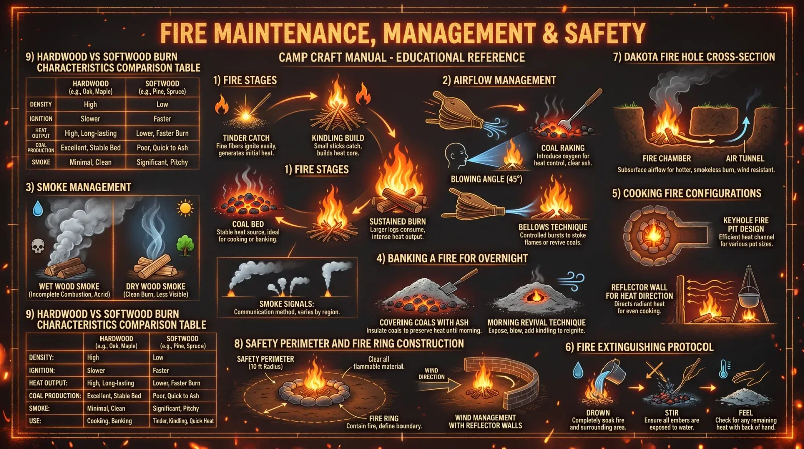
Foreword: Fire commands dominion over life in the wilderness—offering warmth, protection, and sustenance—yet it demands respect and precision in its application. This chapter imparts the sacred protocols for fire mastery: from site selection through construction, control, extinguishment, and emergency suppression. The knowledge herein is both ancient and suppressed, calibrated for survival, environmental sanctity, and legal imperatives. Your mastery of these rites ensures your safety, the preservation of wilderness sanctuaries, and the legacy of those who walk before and after you.
I. Fire Site Selection: The Foundation of Control and Safety
A fire’s dominion begins before the flame ignites. The site you select determines the fire’s behavior, its environmental impact, and your capacity to command it safely.
Criteria for Site Selection
| Criterion | Specification | Purpose |
|---|---|---|
| Distance from Vegetation | Minimum 6 meters (20 feet) clearance | Prevents unintended ignition of brush and trees |
| Distance from Overhead Canopy | Minimum 3 meters (10 feet) clearance | Reduces risk of falling debris and canopy ignition |
| Proximity to Water Source | Minimum 30 meters (100 feet) | Prevents contamination and preserves aquatic ecosystems |
| Terrain | Flat or gently sloping ground | Ensures fire stability and reduces fire spread risk |
| Wind Exposure | Sheltered from prevailing winds | Limits fire spread and smoke dispersion |
| Soil Type | Mineral soil or bare rock preferred | Reduces ground fuel and fire penetration |
Step-by-Step Site Selection Protocol
- Survey the area for potential hazards: overhanging branches, dry grasses, and flammable debris.
- Measure distances using a pace count or measuring tape to ensure clearance meets or exceeds table values.
- Check wind direction by observing smoke or using a portable anemometer; choose a sheltered position.
- Identify soil composition by scraping away organic material; select mineral soil or bare rock surfaces as fire base.
- Confirm legal compliance with local regulations (see Legal Considerations, Section VII).
II. Fire Pit Construction: Engineering the Controlled Flame
The fire pit is the physical anchor of your fire’s order. Its design must prioritize containment, airflow, and ease of extinguishment.
Fire Pit Types and Construction
| Fire Pit Type | Description | Construction Materials | Best Use Case |
|---|---|---|---|
| Dug Pit | Excavated hole 15–30 cm deep and 50 cm wide | Shovel, digging stick | Minimal impact, low wind areas |
| Rock Ring Pit | Circle of stones 50 cm diameter, 20 cm height | Stones from site, digging tool | Ventilated, stable fires |
| Raised Fire Platform | Elevated rock or soil platform 30 cm high | Stones, soil | Wet or snow-covered ground |
| Reflector Wall Pit | Rock wall built on one side to reflect heat | Stones | Cold weather, cooking |
Step-by-Step Fire Pit Construction Protocol
- Clear the site of all organic debris within a 1-meter radius, removing leaves, sticks, and grass.
- Excavate the pit to the appropriate depth and diameter based on chosen fire pit type using a shovel or digging stick.
- Line the pit with mineral soil or rocks to prevent heat transfer to underlying organic layers.
- Construct containment features:
- For rock ring, arrange stones tightly to form a continuous barrier.
- For raised platforms, build a stable platform of stones or compacted soil.
- For reflector walls, stack stones securely on the windward side.
- Create airflow channels: Leave a 10 cm gap or chimney effect for oxygen intake to maintain combustion efficiency.
- Test airflow by lighting a small kindling bundle; adjust stone placement to optimize flame stability.
III. Fire Size Recommendations: Balancing Efficacy and Safety
Fire size dictates its utility for cooking, warmth, and signaling while influencing safety and environmental impact.
Fire Size Parameters
| Purpose | Diameter (cm) | Height (cm) | Fuel Load (kg) | Expected Burn Time (hours) |
|---|---|---|---|---|
| Cooking | 30–50 | 20–30 | 2–4 | 1–2 |
| Warmth | 50–100 | 30–50 | 4–8 | 2–4 |
| Signaling | 100–150 | 50–70 | 8–15 | 3–5 |
| Night Campfire | 70–100 | 30–40 | 5–10 | 4–6 |
IV. Fuel Types and Burn Times: Mastering Energy Sources
Selecting the right fuel optimizes fire control, longevity, and minimal environmental disturbance.
Common Fuel Types and Characteristics
| Fuel Type | Description | Average Burn Time (minutes/kg) | Notes |
|---|---|---|---|
| Dry Pine Needles | Lightweight, high resin | 15–20 | Produces intense flames, high smoke |
| Hardwood Logs | Oak, maple, hickory | 60–90 | Burns steadily, low smoke |
| Softwood Logs | Pine, fir | 30–45 | Burns quickly, moderate smoke |
| Twigs and Small Branches | Diameter < 2 cm | 10–15 | Used for kindling and initial flame |
| Charcoal | Manufactured, dense | 90–120 | Consistent heat, low smoke, requires ignition |
V. Fire Ignition and Maintenance Protocols
Mastery of ignition and maintenance ensures efficient fuel use and fire stability.
Step-by-Step Ignition Protocol
- Gather fuel: Collect twigs, small branches, and progressively larger logs as per fuel type chart.
- Arrange kindling: Use the teepee or log cabin method for optimal airflow.
- Ignite tinder: Use ferrocerium rod or magnesium block with a striker as primitive ignition sources.
- Nurture flame: Gently blow at the base to supply oxygen; avoid overfeeding fuel.
- Add fuel gradually: Introduce larger logs once the kindling is fully combusting.
- Maintain fire: Monitor flame size and add fuel to sustain required heat without exceeding size limits.
VI. Smoke Management: Minimizing Toxicity and Visibility
Smoke is both a signal and a hazard. Proper management reduces health risks and environmental impact.
Techniques for Smoke Reduction
| Technique | Procedure | Outcome |
|---|---|---|
| Use Dry, Seasoned Wood | Ensure wood has <20% moisture content | Produces cleaner, less dense smoke |
| Maintain High Combustion Temperature | Keep flame bright and steady | Reduces incomplete combustion products |
| Incorporate Green Branches Sparingly | Add fresh leaves for smoke signal only | Controls smoke volume and density |
| Position Fire Downwind | Build fire on leeward side relative to camp | Directs smoke away from occupants |
VII. Fire Extinguishing Protocols: Ensuring Complete Quenching
Incomplete extinguishment is the most common cause of wildfires. Follow this precise protocol to guarantee total fire death.
Step-by-Step Extinguishing Procedure
- Allow fire to burn down: Reduce flame size to hot embers before extinguishing.
- Spread embers: Use a stick or shovel to break apart logs and coals, dispersing heat.
- Douse with water: Apply water liberally until hissing stops; saturate all embers and surrounding soil.
- Stir ashes: Mix ashes and wet soil to expose hidden embers; repeat dousing and stirring.
- Check temperature: Place the back of your hand near ashes; no heat should be felt within 10 cm.
- Cover with soil: Once cool, cover pit with mineral soil to prevent re-ignition.
- Final verification: Inspect site after 10 minutes for any smoke, heat, or ember glow.
VIII. Environmental Impact Minimization: Preserve the Sacred Wild
Fire use in the wilderness carries the responsibility to preserve natural sanctuaries.
Best Practices
- Use established fire rings or pits when available to reduce ground scarring.
- Limit fire size to essential needs only.
- Collect dead and downed wood rather than live branches.
- Avoid fires in sensitive habitats such as alpine meadows or peatlands.
- Remove all non-organic debris from fire site post-extinguishment.
- Pack out all waste; never burn plastics or waste materials.
IX. Emergency Fire Suppression Techniques
When fire escapes control, rapid action is required. These techniques are last-resort but lifesaving.
Manual Suppression Tools and Methods
| Tool | Construction Instructions | Usage Protocol |
|---|---|---|
| Fire Beater | 1. Cut a flat, sturdy branch ~60 cm long | 1. Use to smother flames by beating down |
| 2. Attach a wet burlap sack or leather piece | 2. Work from fire edge inward | |
| Fire Rake | 1. Sharpen a sturdy stick to a spade shape | 1. Scrape burning material away |
| 2. Attach handle for leverage | 2. Create fire break trenches | |
| Water Carrier | 1. Use tightly sealed containers or bladders | 1. Apply water directly to flames and embers |
Suppression Protocol
- Alert all personnel and coordinate fire control efforts.
- Establish fire breaks by removing fuel around fire perimeter using rake or shovel.
- Apply water or use fire beaters to smother flames.
- Cool hot spots thoroughly with water or dirt.
- Monitor fire area continuously for rekindling for minimum of 24 hours.
X. Legal Considerations and Compliance
Fire use in wilderness is subject to strict legal frameworks to protect ecosystems and human safety.
| Jurisdiction Type | Common Restrictions | Penalties | Notes |
|---|---|---|---|
| National Parks | Fire bans during dry seasons, permit required | Fines up to $5,000, imprisonment | Always check local regulations |
| State Forests | Fire only in designated areas, seasonal limits | Fines and access revocation | Use official fire rings only |
| Private Lands | Owner permission required, local ordinances | Civil and criminal liability | Verify ownership and rules |
| Wilderness Areas | Fire restricted to minimal-impact methods | Heavy fines | Use portable stoves if required |
XI. Summary Tables for Quick Reference
Fire Pit Dimensions and Fuel Load
| Fire Purpose | Diameter (cm) | Depth (cm) | Fuel Load (kg) | Burn Time (hours) |
|---|---|---|---|---|
| Cooking | 30–50 | 15–30 | 2–4 | 1–2 |
| Warmth | 50–100 | 20–30 | 4–8 | 2–4 |
| Signaling | 100–150 | 25–40 | 8–15 | 3–5 |
Fuel Types and Burn Times
| Fuel Type | Moisture Content | Burn Time (minutes/kg) | Smoke Level |
|---|---|---|---|
| Dry Pine Needles | <15% | 15–20 | High |
| Hardwood Logs | <20% | 60–90 | Low |
| Softwood Logs | <20% | 30–45 | Moderate |
| Twigs | <15% | 10–15 | Moderate |
| Charcoal | 0% (manufactured) | 90–120 | Low |
Conclusion
The sacred art of fire management demands unwavering discipline, precise technique, and reverence for the natural world. Fire is a tool of survival and transformation; wield it with respect, mastery, and responsibility. The protocols in this volume empower you to control fire with confidence, minimize environmental impact, and respond decisively to emergencies. Carry this knowledge as a torch in the wilderness—illuminating your path, defending your life, and honoring the wild sanctuaries you traverse.
For related protocols on water purification and shelter construction, consult Volume VIII: The Water Codex, Chapter II, and Volume V: The Shelter Codex, Chapter I.
<!-- SECTION 14 -->
Volume IV: Foraging by Biome: Identification and Harvesting
Preface
This volume is a sacred transmission of the essential knowledge for the gathering of sustenance within diverse biomes. The ability to identify, harvest, and prepare edible flora and fungi underpins survival and the mastery of environment. This is not casual knowledge but a codified art of life and death, passed through the ages and now entrusted to you, the chosen apprentice. Every procedure outlined here demands strict adherence to avoid fatal errors.
Chapter I: Foraging in Forest Biomes

I.A. Forest Biome Overview
Temperate and boreal forests contain an abundance of edible plants and fungi. Their dense canopies and rich soil ecosystems support diverse species. Correct identification hinges on morphological features, seasonality, and habitat specifics.
I.B. Key Edible Plants and Fungi in Forest Biomes
| Species Name | Identification Markers | Nutritional Values (per 100g) | Preparation Notes |
|---|---|---|---|
| Morel Mushroom (Morchella spp.) | Honeycomb cap, hollow stem, spring season, found near dead elm or ash trees | Calories: 31 kcal, Protein: 3.1g, Fiber: 2.8g | Must be cooked thoroughly; toxic when raw |
| Stinging Nettle (Urtica dioica) | Serrated leaves with stinging hairs, grows in shaded areas | Vitamins A, C, K; Iron: 1.9mg | Boil to neutralize stinging hairs; use leaves for soup or tea |
| Wild Ramps (Allium tricoccum) | Broad, smooth leaves, white bulbs, spring emergence | Vitamins A, C; Allicin compounds | Clean bulbs; sauté or boil to reduce strong flavor |
| Chanterelle (Cantharellus cibarius) | Funnel-shaped, false gills, golden-yellow color, summer-fall | Vitamin D, Potassium: 506mg | Clean with brush; cook to improve digestibility |
I.C. Step-by-Step Identification Protocol for Morel Mushrooms
- Locate areas with decaying hardwood, especially elm and ash trees, during early spring.
- Observe the cap structure: it must exhibit a honeycomb-like network of ridges and pits.
- Confirm the stem is hollow from base to cap.
- Handle carefully to avoid confusing with toxic false morels, which have irregular caps and chambered stems.
- Harvest only mature specimens, avoiding young or overly old ones.
- Record GPS location for sustainable re-harvesting avoidance and ecological impact monitoring.
I.D. Sustainable Harvesting Protocol – Forest Plants and Fungi
- Harvest no more than 30% of any single plant or fungi cluster.
- Use a clean, sharp knife to cut mushrooms at the base to minimize mycelium damage.
- Avoid uprooting plants; collect leaves or bulbs only when surplus is evident.
- Rotate harvesting sites annually to prevent depletion.
- Document harvest date, quantity, and location in a field log for ongoing resource management.
I.E. Seasonality Table: Forest Biome Edibles
| Species | Prime Harvest Season | Secondary Season |
|---|---|---|
| Morel Mushroom | April - June | None |
| Stinging Nettle | April - September | Early Spring, Late Fall |
| Wild Ramps | March - May | None |
| Chanterelle | July - October | Late Spring |
I.F. Preparation Protocol for Stinging Nettle
- Wear gloves to prevent skin irritation.
- Collect fresh leaves in the morning when dew is present.
- Rinse thoroughly in cold water.
- Boil leaves in rapidly boiling water for 5 minutes to neutralize stinging hairs.
- Drain and rinse again in cold water.
- Use as spinach substitute in soups or sautés.
Chapter II: Foraging in Desert Biomes
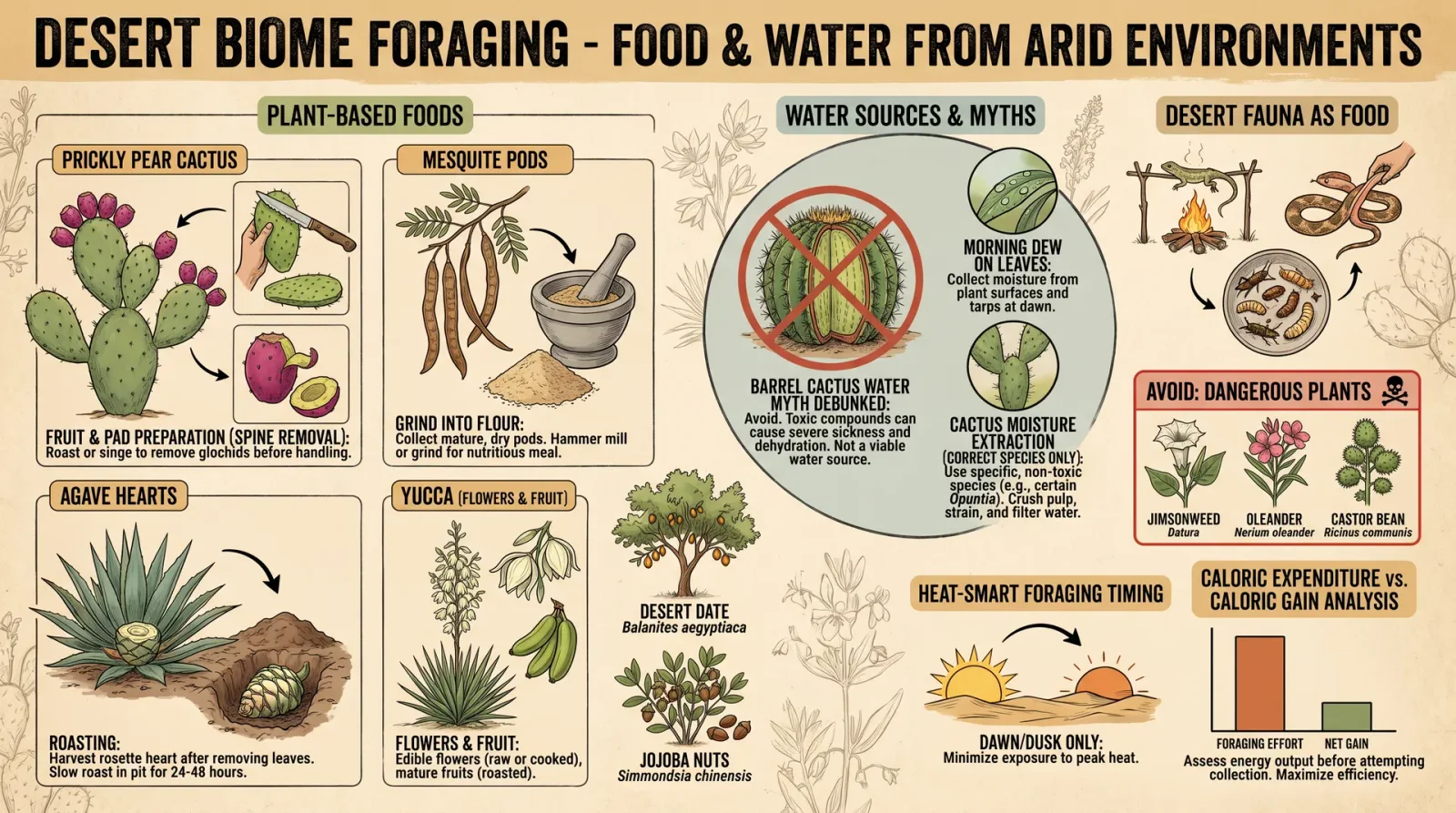
II.A. Desert Biome Overview
Deserts present extreme conditions with sparse vegetation. Edible plants are often succulent, adapted for water storage, and require precise identification to avoid toxic species.
II.B. Key Edible Plants in Desert Biomes
| Species Name | Identification Markers | Nutritional Values (per 100g) | Preparation Notes |
|---|---|---|---|
| Prickly Pear Cactus (Opuntia spp.) | Flat pads (nopales) with small spines; fruits (tunas) are oval and red | Calories: 41 kcal, Fiber: 3.6g, Vitamin C | Remove spines carefully; pads grilled or boiled; fruits peeled and eaten raw |
| Mesquite Beans (Prosopis spp.) | Long pods, sweet pulp, grows on mesquite trees | Protein: 11g, Carbohydrates: 70g | Pods dried, ground into flour; used for baking |
| Desert Agave (Agave deserti) | Rosette of spiny leaves; flowering stalk appears after years | Carbohydrates, inulin | Harvest flower stalk before bloom; roast to extract sugars |
II.C. Identification and Harvesting Protocol for Prickly Pear Cactus Pads
- Locate mature cactus pads (nopales) free of rot or excessive spines.
- Wear thick gloves and use tongs to avoid injury.
- Remove small spines by scraping with a dull knife or burning briefly over fire.
- Cut pads at the base with a sharp knife.
- Transport pads in breathable containers to prevent spoilage.
- Harvest only 2-3 pads per cactus plant to maintain health.
II.D. Sustainable Harvesting Protocol – Desert Plants
- Limit harvest to 25% of available pads or pods per plant.
- Avoid damaging root systems by cutting only above-ground parts.
- Harvest during early morning or late evening to reduce plant stress.
- Observe regeneration cycles, allowing plants 1-2 years before re-harvesting.
- Dispose of plant waste away from harvest site to avoid attracting herbivores or pests.
II.E. Seasonality Table: Desert Biome Edibles
| Species | Prime Harvest Season | Secondary Season |
|---|---|---|
| Prickly Pear Pads | April - June | September - October |
| Prickly Pear Fruit | June - September | None |
| Mesquite Beans | August - November | None |
| Desert Agave | February - April | None |
II.F. Preparation Protocol for Mesquite Bean Flour
- Collect mature pods when dry and brown.
- Remove seeds and pods' outer husks.
- Dry pods completely in sun or low-temperature oven (~50°C).
- Grind pods into fine flour using a mortar and pestle or hand mill.
- Sift flour to remove coarse particles.
- Use flour in bread or porridge; mesquite flour imparts sweet, nutty flavor.
Chapter III: Foraging in Tundra Biomes
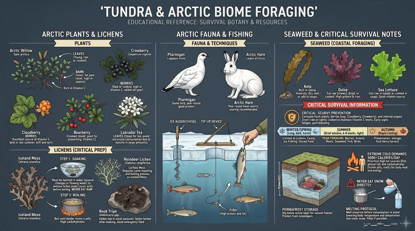
III.A. Tundra Biome Overview
The tundra's short growing season and permafrost limit plant diversity but provide nutrient-dense species adapted to cold. Foraging here demands precision in timing and identification.
III.B. Key Edible Plants in Tundra Biomes
| Species Name | Identification Markers | Nutritional Values (per 100g) | Preparation Notes |
|---|---|---|---|
| Crowberry (Empetrum nigrum) | Small black berries, evergreen ground cover | Calories: 50 kcal, Vitamin C | Eaten raw or cooked; berries have tart flavor |
| Cloudberry (Rubus chamaemorus) | Orange-yellow berries, grows in boggy areas | Vitamin C, antioxidants | Harvest ripe berries; use fresh or cooked |
| Arctic Willow (Salix arctica) | Low shrub, small oval leaves, hairy stems | Vitamin C, tannins | Use young leaves and shoots; boil to reduce tannins |
III.C. Identification Protocol for Cloudberries
- Locate wet, boggy tundra areas with peaty soil.
- Identify low-lying shrubs with trifoliate leaves.
- Inspect for orange-yellow, soft berries in late July - August.
- Harvest only ripe, plump berries to avoid stomach upset.
- Avoid unripe berries, which are sour and potentially irritating.
III.D. Sustainable Harvesting Protocol – Tundra Plants
- Collect no more than 20% of berries or leaves from a single area.
- Avoid trampling vegetation around harvest sites.
- Harvest during peak ripeness to ensure seed maturity for propagation.
- Use hand tools carefully to avoid damaging roots or stems.
- Rotate harvest sites seasonally to allow plant regeneration.
III.E. Seasonality Table: Tundra Biome Edibles
| Species | Prime Harvest Season | Secondary Season |
|---|---|---|
| Crowberry | August - September | None |
| Cloudberry | Late July - August | None |
| Arctic Willow Leaves | June - July | Early September |
III.F. Preparation Protocol for Arctic Willow Leaves
- Harvest young leaves and shoots during early summer.
- Rinse thoroughly in cold water.
- Boil leaves in water for 10 minutes to reduce tannins.
- Drain and discard boiling water.
- Use boiled leaves as tea or cooked vegetable.
Chapter IV: Foraging in Tropical Biomes
IV.A. Tropical Biome Overview
Tropical forests and jungles feature dense biodiversity with numerous edible plants and fungi. Identification requires attention to leaf shape, flower morphology, and fruit characteristics.
IV.B. Key Edible Plants and Fungi in Tropical Biomes
| Species Name | Identification Markers | Nutritional Values (per 100g) | Preparation Notes |
|---|---|---|---|
| Breadfruit (Artocarpus altilis) | Large, lobed leaves; large round fruit with starchy flesh | Calories: 103 kcal, Carbohydrates: 27g | Peel and boil or roast; edible when unripe or ripe |
| Cassava (Manihot esculenta) | Palmate leaves; tuberous roots with cyanogenic glycosides | Calories: 160 kcal, Carbohydrates: 38g | Roots must be peeled, soaked, and cooked thoroughly to remove toxins |
| Termite Mushroom (Termitomyces spp.) | Large cap, grows symbiotically with termite mounds | Protein: 20g, Fiber: 3.5g | Clean dirt thoroughly; cook completely before consumption |
IV.C. Identification Protocol for Cassava Roots
- Identify palmate leaves with 5-7 lobes.
- Locate tuberous roots underground; roots are conical and can be 30-60cm long.
- Cut a small sample; bitter cassava will have a sharp, acrid taste.
- Avoid bitter varieties if detoxification means unavailable.
- Harvest roots in dry season to minimize rot risk.
IV.D. Sustainable Harvesting Protocol – Tropical Plants and Fungi
- Harvest no more than 40% of fruit or roots from a single plant.
- Leave upper roots intact to maintain plant vitality.
- Harvest mushrooms only when caps are fully expanded.
- Avoid disturbing termite mounds excessively to preserve fungal symbiosis.
- Document harvest locations and quantities for ecological balance.
IV.E. Seasonality Table: Tropical Biome Edibles
| Species | Prime Harvest Season | Secondary Season |
|---|---|---|
| Breadfruit | June - September | December - February |
| Cassava Roots | Year-round | Dry season preferred |
| Termite Mushroom | June - October | None |
IV.F. Preparation Protocol for Cassava Roots
- Peel roots thoroughly to remove outer cortex.
- Rinse peeled roots in clean water.
- Soak roots in water for 24-48 hours, changing water every 12 hours.
- Grate or slice soaked roots.
- Cook roots by boiling or roasting until soft.
- Discard soaking water and initial cooking water to remove residual toxins.
- Use prepared cassava in porridge, bread, or fermented products.
Illustrations and Photographic References
Due to the sacred nature of this codex, detailed illustrations and photographs are provided on the enclosed reference plates (attached separately). These visual aids include macro and micro views of identification markers such as leaf venation, mushroom gill structure, spine morphology, and fruit texture. Apprentices must consult these plates in tandem with field observations to avoid lethal misidentifications.
Final Notes
Mastery of foraging demands rigorous practice and continuous learning. Always cross-reference visual identification with habitat and seasonality data. Harvesting sustainably ensures future abundance and preserves the sanctity of the wild. This volume serves as your definitive guide; failure to adhere to these protocols risks not only your sustenance but your very life.
For protocols on water purification, see Volume VIII: The Water Codex, Chapter II.
For preservation and storage of foraged goods, see Volume VI: The Provisioner's Codex, Chapter IV.
End of Volume IV: Foraging by Biome: Identification and Harvesting
<!-- SECTION 15 -->
Volume IV: Edibility Testing Protocols and Toxicity Avoidance
Chapter I: The Universal Edibility Test and Advanced Toxicity Detection
Introduction In the crucible of survival, the mastery of edibility testing is paramount. Life hinges upon the ability to distinguish nourishing flora from lethal imposters. This volume delivers the Universal Edibility Test (UET) protocol, augmented with advanced toxicity detection methods. It also provides exhaustive data on common poisonous plants, their deceptive look-alikes, symptomatology, and immediate first aid responses. The knowledge enclosed here is classified and life-preserving, born of centuries of suppression and rediscovery.
Section 1: The Universal Edibility Test (UET) — Step-by-Step Protocol
The UET is a rigorous, multi-stage process designed to minimize risk when no prior botanical knowledge exists. It is imperative to adhere strictly to each step. Deviation invites poisoning.
Equipment and Preparation Checklist
| Item | Purpose | Notes |
|---|---|---|
| Sharp knife | For sample collection and preparation | Sterilize before use |
| Fire source | For heat testing (optional) | Use if suspecting heat-labile toxins |
| Watch or timer | To monitor contact and ingestion intervals | Essential for timed observation |
| Water source | For rinsing and dilution | Refer to Volume VIII: The Water Codex, Chapter II |
| Survival notebook | To record observations | Maintain meticulous records |
Step-by-Step Procedure
- Visual Identification and Separation Collect the plant in question along with nearby flora to avoid cross-contamination. Separate leaves, stems, buds, flowers, and roots. Test only one part at a time.
- Contact Test (Skin Sensitivity)
- Rub a small section of the plant part on the inside of your forearm or wrist.
- Wait for 15 minutes.
- Watch for: Redness, burning, itching, swelling, or blistering.
- If reaction occurs, do not proceed. Mark the plant as toxic.
- Lip Contact Test
- Touch the plant part to your lips for 3 minutes.
- Avoid ingestion.
- Watch for: Tingling, burning, numbness, or swelling.
- If symptoms manifest, abort testing.
- Tongue Contact Test
- Place a small piece on the tongue for 15 minutes without chewing or swallowing.
- Watch for: Burning, numbness, bitterness, or unusual taste.
- If any adverse sensation arises, reject the plant.
- Chewing and Holding Test
- Chew a small piece and hold it in the mouth for 15 minutes without swallowing.
- Spit out after the interval.
- Monitor for mouth/throat irritation, unusual taste, or numbness.
- Swallowing Test
- Swallow a small amount (approx. 5 ml or 1 teaspoon) of the plant part.
- Wait for 8 hours, and monitor for symptoms.
- If no symptom appears, proceed to the next step.
- Increased Consumption Test
- Consume a small portion (approx. 30 ml or 2 tablespoons).
- Wait for 24 hours.
- Observe for delayed symptoms.
- Full Meal Test
- If no symptoms are observed, consume a full serving (approx. 100-150 grams) as a meal.
- Continue to observe for 48 hours.
Strict adherence to stepwise observation is mandatory. Symptoms can be immediate or delayed.
Symptoms and Their Significance Table
| Symptom | Possible Toxicity Indication | Immediate Action |
|---|---|---|
| Skin rash, itching, swelling | Contact toxin or allergen | Wash area, avoid ingestion |
| Oral burning, numbness | Irritant or neurotoxin | Spit out immediately, rinse mouth |
| Nausea, vomiting | Gastrointestinal toxin | Induce vomiting if safe, hydrate |
| Dizziness, headache | Neurotoxic or systemic poisoning | Seek shelter, monitor vitals |
| Abdominal pain, diarrhea | Digestive toxin | Hydrate, monitor for dehydration |
| Difficulty breathing | Severe allergic reaction or toxin | Administer epinephrine if available, seek immediate help |
| Seizures, convulsions | Neurotoxin | Protect airway, call for emergency aid |
Section 2: Advanced Toxicity Detection Techniques
Beyond the UET, advanced methods increase detection accuracy, especially in unknown environments.
2.1 Heat Test (Thermal Deactivation)
Many plant toxins are thermolabile and deactivate upon heating.
Procedure:
- Collect a sample of the suspect plant part.
- Boil in clean water for 10 minutes.
- Use the UET protocol on the heated sample.
Note: Some toxins (e.g., glycosides) persist after heat treatment; the heat test is supplementary only.
2.2 Smell and Volatile Compound Detection
Toxic plants often emit acrid or pungent odors.
Procedure:
- Crush the plant part lightly and inhale cautiously from a distance (~20 cm).
- If the scent is sharp, chemical-like, or unpleasant, proceed with extreme caution or reject.
2.3 Insect and Animal Interaction Observation
Insect damage or animal feeding behavior provides clues.
- Avoid plants heavily damaged by insects (may indicate toxins).
- If local fauna consume the plant without ill effect, it may be considered safer but not guaranteed. Always verify with UET.
2.4 Colorimetric Tests (Field Chemical Tests)
Materials:
- Iodine solution (for starch)
- Benedict’s reagent (for sugars)
- pH strips
Purpose: To detect certain compounds indicating edibility or toxicity.
Procedure:
- Apply reagent to plant extract.
- Observe color change per reagent instructions.
- Use results to cross-reference with known toxin profiles.
Section 3: Common Poisonous Plants, Look-alikes, Symptoms, and First Aid
This table is a critical reference. Memorize and carry a laminated copy during field operations.
| Plant Name | Look-alike(s) | Distinguishing Features | Toxic Part(s) | Symptoms | Immediate First Aid |
|---|---|---|---|---|---|
| Deadly Nightshade (Atropa belladonna) | Black Nightshade (Solanum nigrum) | Bell-shaped purple flowers, shiny black berries | Berries, leaves | Dilated pupils, hallucinations, dry mouth, tachycardia | Induce vomiting, activated charcoal, seek medical help |
| Water Hemlock (Cicuta maculata) | Wild Parsnip (Pastinaca sativa) | Hollow, purple-spotted stems, umbrella-shaped white flowers | Roots, stems | Seizures, nausea, respiratory failure | Immediate evacuation, activated charcoal, airway support |
| Poison Hemlock (Conium maculatum) | Queen Anne’s Lace (Daucus carota) | Purple-spotted stems, fern-like leaves | Entire plant | Muscle paralysis, respiratory arrest | Call emergency services, maintain airway, administer antidote if available |
| Foxglove (Digitalis purpurea) | Campanula (Campanula spp.) | Bell-shaped purple flowers, ovate leaves | Leaves, flowers | Cardiac arrhythmia, vomiting | Monitor heart, avoid ingestion, seek urgent care |
| Jimsonweed (Datura stramonium) | Thorn Apple (Solanum spp.) | Large trumpet-shaped flowers, spiny seed pods | Leaves, seeds | Hallucinations, dry mouth, tachycardia | Activated charcoal, sedation, medical intervention |
| Poison Ivy (Toxicodendron radicans) | Virginia Creeper (Parthenocissus quinquefolia) | Leaves of three, shiny, with smooth edges (Ivy) vs. five leaflets (Creeper) | Leaves, stems | Contact dermatitis, itching, blistering | Wash skin thoroughly, corticosteroids for rash |
| Castor Bean (Ricinus communis) | Coral Bean (Erythrina herbacea) | Large, palmate leaves, spiny seed pods | Seeds (ricin) | Severe abdominal pain, vomiting, diarrhea | No antidote; activated charcoal, supportive care |
Section 4: Detoxification Methods
Should accidental ingestion or dermal exposure occur, immediate detoxification can be life-saving.
4.1 Dermal Exposure Detoxification
- Rinse the affected area with running water for 15 minutes minimum.
- Apply a paste of bentonite clay or activated charcoal if available to absorb toxins.
- Cover with sterile dressing to prevent secondary contamination.
- Administer oral antihistamines if swelling or itching persist.
4.2 Ingestion Detoxification
Caution: Never induce vomiting unless instructed and safe to do so.
- Administer activated charcoal at 1g/kg body weight within 1 hour of ingestion if available.
- Provide small sips of water or oral rehydration solution to prevent dehydration unless vomiting or unconscious.
- Monitor vital signs continuously.
- For neurotoxic symptoms, maintain airway and prepare for artificial respiration.
- Transport to advanced medical facility as soon as possible.
Section 5: Case Studies
Case Study 1: Misidentification of Deadly Nightshade in Forest Survival
A group of four survivors consumed berries identified by a novice as edible black nightshade. Within 30 minutes, two exhibited severe hallucinations, dry mouth, and tachycardia, consistent with belladonna poisoning. The group applied the UET protocol post-facto and noted lip contact burning and tongue numbness, confirming toxicity. Immediate administration of activated charcoal and hydration stabilized symptoms until rescue.
Lesson: Always perform UET before consumption, especially with similar-looking species.
Case Study 2: Inadequate Detoxification after Water Hemlock Ingestion
A solo traveler mistakenly consumed a root they believed to be wild carrot. Onset of seizures and abdominal pain occurred within an hour. Attempts to induce vomiting delayed activated charcoal administration. The patient suffered respiratory arrest due to delayed airway support.
Lesson: Inducing vomiting can worsen certain poisonings. Always prioritize airway management and timely charcoal administration.
Section 6: Safety Checklists
Pre-Testing Checklist
| Item | Status (✓/✗) | Notes |
|---|---|---|
| Plant part separated correctly | ||
| Skin contact test completed | ||
| Lip contact test completed | ||
| Tongue contact test completed | ||
| Chewing test completed | ||
| Swallowing test completed | ||
| Timed symptom observation recorded |
Emergency Response Checklist
| Item | Status (✓/✗) | Notes |
|---|---|---|
| Activated charcoal available | ||
| Water source secured | ||
| First aid kit accessible | ||
| Communication device functional | ||
| Evacuation plan established |
Conclusion The Universal Edibility Test combined with advanced toxicity detection techniques forms the bedrock of survival nutrition. Coupled with comprehensive plant identification and emergency protocols, mastery of this volume will ensure life preservation in the most hostile environments. This knowledge is sacred; wield it with precision and respect.
For water purification, refer to Volume VIII: The Water Codex, Chapter II. For fungal and animal edibility, consult Volume V: Faunal and Fungal Foraging Codex.
End of Volume IV, Chapter I
<!-- SECTION 16 -->
Volume IV: Wild Game Procurement Techniques
Chapter I: Introduction to Wild Game Procurement
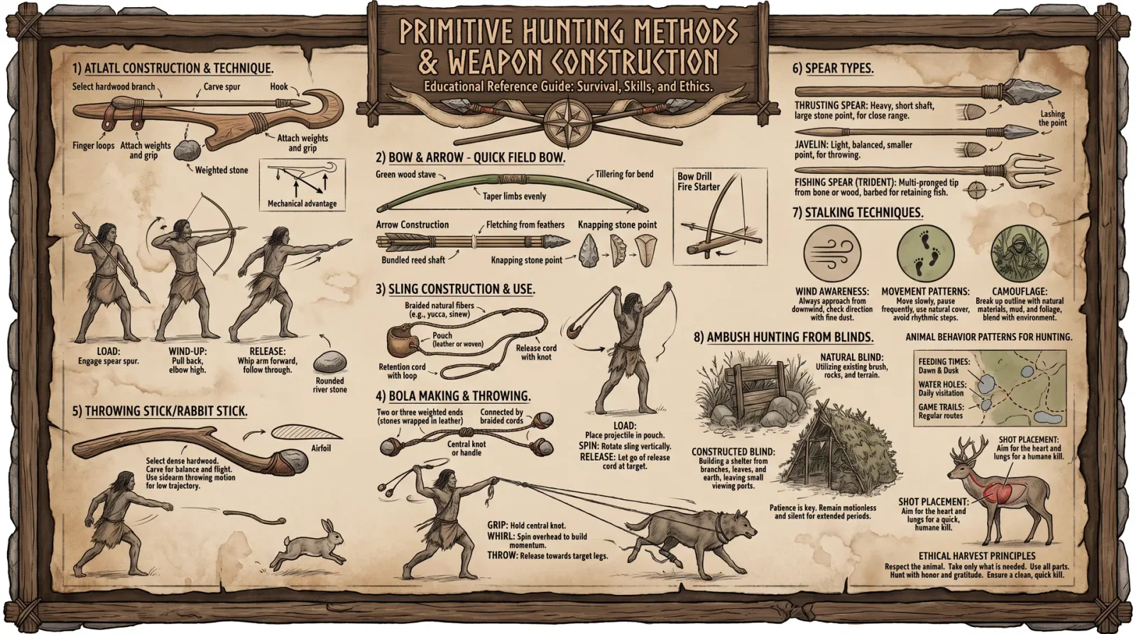
The mastery of wild game procurement stands as a cornerstone of survival and sustenance in the natural world. This volume, "Wild Game Procurement Techniques," details the sacred and ancient arts of hunting, trapping, and fishing. Each method is adapted to diverse environments, ensuring versatility and reliability. This chapter serves as the definitive manual for the construction of snares, traps, fishing lines, and primitive weapons, alongside comprehensive protocols for processing and preserving game.
Chapter II: Animal Behavior, Seasonal Availability, and Ethical Considerations
Before engaging in game procurement, one must understand the behavioral patterns, seasonal availability, and ethical constraints governing the target species. This knowledge maximizes success and ensures sustainable practices.
Table 2.1: Key Animal Behavior and Seasonal Availability Matrix
| Species | Habitat Type | Peak Activity Period | Seasonal Availability | Key Behavioral Traits | Ethical Harvest Considerations |
|---|---|---|---|---|---|
| White-tailed Deer | Forest, Mixed Wood | Dawn & Dusk | Fall (Oct-Dec) | Crepuscular; strong herd instincts | Avoid females with fawns; harvest mature bucks only |
| Eastern Cottontail | Brush, Fields | Night (Nocturnal) | Year-round | Solitary; highly alert | Limit take to prevent population decline |
| Wild Turkey | Forest, Grassland | Morning & Evening | Spring (March-May) | Roosts in trees; sensitive to noise | Harvest only males during breeding season |
| Beaver | Wetlands, Rivers | Nocturnal | Fall & Winter | Territorial; lodges on water | Target only mature individuals; avoid breeding season |
| Brook Trout | Cold, Clear Streams | Dawn & Dusk | Spring & Fall | Territorial; feeds on surface insects | Adhere to size limits; avoid spawning streams |
| Pheasant | Grassland, Farmland | Early Morning | Fall (Sept-Nov) | Ground-dwelling; quick flush flight | Avoid overharvesting in small habitats |
Note: Seasonal availability reflects peak hunting windows optimized for animal health and population sustainability.
Chapter III: Hunting Protocols
Section 3.1: Primitive Weapons Construction
The art of primitive weapons construction demands precision and reverence for materials. This section details the exact protocols for crafting bows, arrows, spears, and clubs.
3.1.1: Bow Construction Protocol
Materials Required:
- Flexible hardwood (e.g., Osage Orange, Hickory) 1.5 meters long, 3-4 cm diameter
- Natural cordage (sinew, rawhide strips, or plant fibers)
- Stone or bone knife
- Sandstone for smoothing
- Resin or pitch for waterproofing
Step-by-Step Instructions:
- Select and Prepare the Bow Stave:
- Identify a straight, knot-free branch of flexible hardwood.
- Remove bark with stone knife.
- Shape the stave into a gentle curve, tapering from center (handle) to tips.
- Tillering:
- Slowly flex the stave to identify weak points.
- Remove wood from thicker areas using a stone scraper until the bow bends evenly.
- Notching:
- Carve shallow notches at both ends for string attachment.
- String Construction:
- Twist sinew or plant fibers into a strong cord approximately 1.6 meters long.
- Dry and tighten the string to achieve proper tension.
- Assembly:
- Attach string to notches.
- Test bow flexibility; adjust tension as necessary.
- Waterproofing:
- Apply resin or pitch to stave and string to protect from moisture.
- Curing:
- Hang bow in a dry place for 1-2 weeks before use.
3.1.2: Arrow Fabrication Protocol
Materials Required:
- Straight wooden shafts, 60-70 cm length, diameter 0.8-1.2 cm
- Stone, bone, or metal for arrowheads
- Feathers for fletching
- Natural adhesives (pine resin)
Step-by-Step Instructions:
- Shaft Preparation:
- Select straight, lightweight wood; remove bark.
- Smooth shaft with sandstone.
- Arrowhead Attachment:
- Shape arrowhead by flint knapping or carving.
- Notch shaft end to firmly bind arrowhead using sinew and resin.
- Fletching:
- Split feathers longitudinally.
- Attach three feathers evenly spaced around the shaft near the rear using sinew and resin.
- Nock Carving:
- Cut a small notch at the rear end to fit the bowstring.
- Drying:
- Allow all adhesives to cure for 24 hours.
3.1.3: Spear Construction Protocol
Materials Required:
- Hardwood shaft, 1.5 to 2 meters long, 2-3 cm diameter
- Sharpened stone or bone spearhead
- Cordage (sinew or plant fibers)
Step-by-Step Instructions:
- Shaft Selection:
- Choose a sturdy, straight branch.
- Remove bark and smooth surface.
- Spearhead Attachment:
- Sharpen stone or bone.
- Bind spearhead to shaft tightly with sinew and resin.
- Reinforcement:
- Wrap binding area with additional sinew layers.
- Point Hardening:
- Carefully char spear tip in fire for increased durability.
- Drying:
- Cure for 24 hours before use.
3.1.4: Club Construction Protocol
Materials Required:
- Hardwood branch, 40-50 cm length, thick diameter
- Stone hammer for shaping
- Sandstone for smoothing
Step-by-Step Instructions:
- Material Selection:
- Choose a heavy, dense wood branch.
- Remove bark from striking end.
- Shaping:
- Use stone hammer to flatten or round striking face.
- Smooth with sandstone.
- Handle Formation:
- Carve handle region to fit hand comfortably.
- Optional Reinforcement:
- Wrap handle with leather strips or sinew for grip.
Section 3.2: Hunting Techniques
3.2.1: Stalking and Ambush
- Pre-Hunt Scouting:
- Identify animal trails, feeding sites, and water sources.
- Wind Direction Awareness:
- Approach from downwind to prevent scent detection.
- Camouflage:
- Utilize natural materials to break outline.
- Stealth Movement:
- Move slowly, pausing frequently.
- Shot Placement:
- Aim for vital areas: heart or lungs.
- Tracking:
- Follow blood trails carefully to retrieve game.
Chapter IV: Trapping Protocols
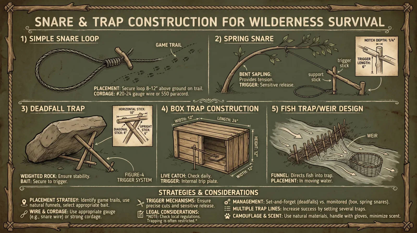
Trapping presents an energy-efficient alternative to active hunting. Proper construction and placement of traps are paramount.
Section 4.1: Snare Construction and Placement
Materials Required:
- Flexible wire, strong plant fiber, or sinew (length: 1 meter per snare)
- Forked stick or sapling (height 50-70 cm)
- Trigger mechanism materials (small sticks, bent sapling)
4.1.1: Basic Snare Construction
Step-by-Step Instructions:
- Loop Formation:
- Form a noose loop of approximately 15-20 cm diameter.
- Ensure the loop tightens when pulled.
- Anchor Setup:
- Secure one end of wire or fiber to a sturdy forked stick or sapling.
- Trigger Assembly:
- Use a bent sapling or trigger stick to hold the noose in a raised position.
- Placement:
- Set snares on animal trails or near burrows.
- Conceal with leaves or grass, keeping loop open.
- Testing:
- Gently pull trigger to ensure snare tightens and trap resets.
4.1.2: Deadfall Trap Protocol
Materials Required:
- Heavy rock or log (weight >10 kg)
- Trigger sticks (small diameter sticks)
- Bait (fruit, meat, or scented lure)
Step-by-Step Instructions:
- Trigger Construction:
- Carve three sticks: trigger, prop, and bait stick.
- Setup:
- Position heavy rock or log elevated by trigger assembly.
- Bait Placement:
- Attach bait to bait stick within trap area.
- Activation:
- Ensure trigger releases prop stick when bait is disturbed, causing trap to fall.
- Concealment:
- Cover trap area lightly with leaves and twigs.
Section 4.2: Pitfall Trap Construction Protocol
Materials Required:
- Shovel or digging tool
- Sharp stakes (optional)
- Camouflage material (leaves, branches)
Step-by-Step Instructions:
- Digging:
- Excavate pit 60 cm deep, 30 cm diameter.
- Stake Placement (Optional):
- Insert sharpened stakes vertically inside pit.
- Covering:
- Place thin branches over pit.
- Overlay with leaf litter concealing pit.
- Baiting:
- Scatter bait leading into pit.
- Marking:
- Mark area discreetly for later inspection.
Chapter V: Fishing Techniques
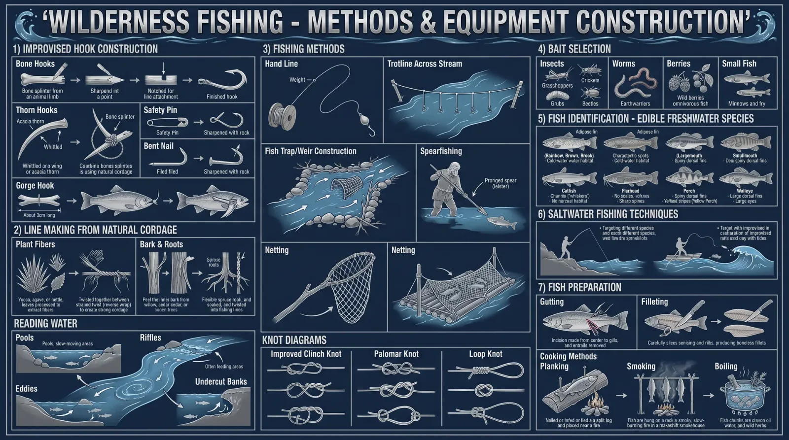
Fishing methods must be tailored to water body type and fish species.
Section 5.1: Fishing Line and Hook Fabrication
Materials Required:
- Plant fibers (nettles, flax) or animal sinew
- Small bone or thorn for hooks
- Stone knife
5.1.1: Fishing Line Construction
Step-by-Step Instructions:
- Fiber Harvesting:
- Collect long, strong fibers.
- Processing:
- Strip fibers and twist into threads.
- Twisting:
- Combine threads into a single line approximately 3 meters long.
- Strength Testing:
- Apply tension gradually; reinforce weak spots.
5.1.2: Hook Fabrication
Step-by-Step Instructions:
- Material Selection:
- Pick sturdy bone fragment or thorn.
- Shaping:
- Carve a hook shape with a pointed barb.
- Attachment:
- Bind hook to fishing line using strong knot and resin.
Section 5.2: Fishing Methods
5.2.1: Handline Fishing Protocol
- Baiting:
- Use insects, worms, or small fish.
- Casting:
- Lower line into water near fish habitats.
- Waiting:
- Maintain tension; detect bites by line movement.
- Setting Hook:
- Pull line sharply when bite detected.
- Retrieval:
- Slowly reel in fish by hand.
5.2.2: Fish Trap Construction Protocol
Materials Required:
- Flexible branches or reeds
- Cordage (sinew or plant fibers)
Step-by-Step Instructions:
- Frame Assembly:
- Weave branches into conical or cylindrical shape.
- Entrance Funnel:
- Construct narrow funnel entrance to channel fish inside.
- Placement:
- Submerge trap in shallow, flowing water.
- Baiting:
- Place bait inside trap to attract fish.
- Monitoring:
- Check trap daily; remove catch promptly.
Chapter VI: Processing and Preservation
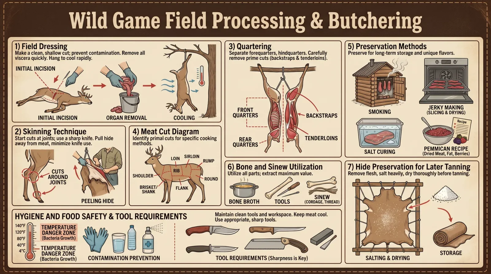
Proper processing and preservation extend the utility of procured game.
Section 6.1: Field Dressing Protocol
- Safety:
- Ensure sharp cutting tools.
- Initial Cuts:
- Place animal on clean surface.
- Cut along the midline from anus to sternum.
- Evisceration:
- Remove internal organs carefully.
- Avoid rupturing intestines or bladder.
- Cooling:
- Expose carcass to air; avoid direct sunlight.
- Transport:
- Use clean cloth to wrap meat.
Section 6.2: Meat Preservation Methods
6.2.1: Drying Protocol
- Slicing:
- Cut meat into thin strips (1 cm thick).
- Salting:
- Rub coarse salt liberally on meat.
- Hanging:
- Suspend strips in dry, breezy area away from insects.
- Duration:
- Dry for 3-7 days until leathery.
6.2.2: Smoking Protocol
- Preparation:
- Build smoking rack from green wood.
- Fire Setup:
- Maintain low smoldering fire with hardwood chips.
- Hanging Meat:
- Suspend meat strips above smoke.
- Smoking Time:
- Smoke for 24-48 hours, maintaining consistent smoke.
- Storage:
- Store smoked meat in dry containers.
6.2.3: Fat Rendering and Preservation
- Collection:
- Gather fat trimmings from processed meat.
- Rendering:
- Heat slowly in a container until fat liquefies.
- Straining:
- Pour through fine mesh to remove solids.
- Storage:
- Store in sealed containers; use as cooking fat or preservative.
Chapter VII: Ethical Hunting and Sustainability Protocols
The sacred bond between hunter and prey demands respect and responsibility.
- Selective Harvesting: Target mature animals; avoid breeding individuals.
- Population Monitoring: Regularly assess game abundance.
- Habitat Protection: Avoid habitat destruction during procurement.
- Waste Minimization: Utilize all parts of the animal; no waste permitted.
- Legal Compliance: Adhere to local regulations and seasonal restrictions.
Appendix A: Comprehensive Animal Behavioral Data Table
| Species | Feeding Time | Scent Sensitivity | Hearing Range (Hz) | Visual Acuity | Flight/Flight Distance (m) | Notes |
|---|---|---|---|---|---|---|
| White-tailed Deer | Crepuscular | High | 200-8000 | Moderate | 100 | Extremely alert to sound |
| Eastern Cottontail | Nocturnal | Moderate | 250-6000 | Low | 30 | Relies on quick escape |
| Wild Turkey | Diurnal | Low | 500-12000 | High | 50 | Flushes quickly |
| Beaver | Nocturnal | Moderate | 300-7000 | Low | 20 | Territorial, lodges present |
| Brook Trout | Dawn & Dusk | Low | Limited | Moderate | N/A | Sensitive to water disturbance |
| Pheasant | Early Morning | Moderate | 400-10000 | Moderate | 60 | Ground-nesting |
Appendix B: Material Sources and Substitutions
| Material | Primary Source | Secondary Substitution | Notes |
|---|---|---|---|
| Hardwood | Osage Orange, Hickory | Ash, Elm | Select based on local availability |
| Cordage | Sinew, Rawhide | Nettles, Flax fibers | Process fibers for strength |
| Arrowhead | Flint, Bone | Hardened Wood | Harden wood by charring |
| Resin/Pitch | Pine Trees | Birch Bark Tar | Use for waterproofing |
| Feathers | Game Birds | Leaves or Bark Strips | Less effective but usable for fletching |
The knowledge contained herein is a sacred trust. Mastery in wild game procurement is not only a skill but a covenant with the earth and its creatures. Every step, every tool, every method must be performed with precision, care, and respect. May this volume serve as your unerring guide in the pursuit of sustenance and survival.
<!-- SECTION 17 -->
The Complete Practitioner's Codex, Volume IV: Insect Protein and Seaweed Harvesting
Chapter I: Identification, Collection, Preparation, and Nutritional Analysis of Edible Insects and Seaweed Species
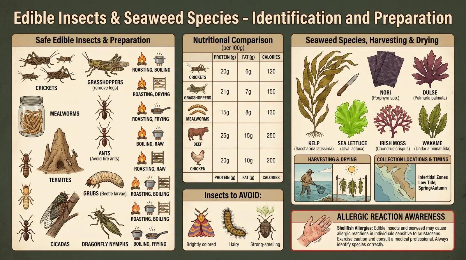
Introduction This volume imparts the sacred and practical knowledge required for the identification, harvesting, preparation, and preservation of two vital survival food sources: insects and seaweed. These sources are rich in protein, essential minerals, and vitamins, indispensable for sustained health in austere environments. This chapter provides exhaustive, step-by-step protocols, technical data tables, and preservation techniques to empower the adept with life-sustaining mastery.
Section 1: Edible Insects
1.1 Identification of Edible Insects
Accurate identification is paramount to avoid toxic or allergenic species. The following table details the primary edible insect species recognized for their high nutritional value, habitat specificity, and safety profile.
| Common Name | Scientific Name | Habitat | Identification Markers | Safety Notes |
|---|---|---|---|---|
| Mealworm | Tenebrio molitor | Decaying wood, stored grain | Cylindrical yellow-brown larvae, hard exoskeleton | Avoid if moldy or contaminated |
| Crickets | Acheta domesticus | Grasslands, fields | Long hind legs for jumping, chirping males | Harvest away from pesticide zones |
| Termites | Isoptera spp. | Dead wood, soil | Soft-bodied, white to pale brown, wings during swarming season | Avoid flying swarms during rainy season |
| Grasshoppers | Caelifera spp. | Grasslands, meadows | Large hind legs, green/brown camouflage | Avoid during pesticide application periods |
| Black Soldier Fly Larvae | Hermetia illucens | Compost piles, organic waste | Creamy white segmented larvae, fast-growing | Must be sourced from clean organic waste |
1.2 Collection Protocols for Insects
Equipment Required:
- Insect net (fine mesh, 1 mm)
- Collection containers with ventilation holes
- Gloves (nitrile or leather)
- Dissection forceps
- Portable magnifier (10x)
- Clean water source for rinsing
Step-by-Step Collection Instructions:
- Site Selection: Identify insect habitats per species data in Table 1. Avoid areas near industrial pollution or pesticide application.
- Time of Day: Collect during early morning or late afternoon when insects are less active and easier to capture.
- Methodology: a. For flying insects (e.g., crickets, termites), sweep the net in arcs at 45 degrees through vegetation or near wood piles.
b. For soil-dwelling larvae, gently sift through decaying wood or organic matter with your hands or forceps. - Handling: Place insects immediately into ventilated containers to prevent suffocation or injury. Avoid overcrowding to reduce stress and mortality.
- Rinsing: Before processing, rinse insects in clean water to remove dirt and potential contaminants.
1.3 Preparation of Insect Protein
Preparation ensures palatability, safety, and digestibility. The following protocol outlines cleaning, cooking, and drying methods.
Step-by-Step Preparation Protocol:
- Initial Cleaning: a. Place insects in a bowl of clean water.
b. Agitate gently for 2 minutes.
c. Remove insects and repeat rinse twice. - Purging (Optional for gut content emptying): a. Place insects on a clean surface without food for 24 hours.
b. Alternatively, feed clean grains to purge gut content. - Cooking: a. Boil insects in water at 100°C for 5 minutes to kill pathogens.
b. Alternatively, roast over dry heat at 150°C for 10 minutes until crisp. - Drying for Preservation: a. Spread cooked insects on a clean, dry surface in direct sunlight or use a dehydrator set at 60°C for 12 hours.
b. Store dried insects in airtight containers with desiccant packets to prevent moisture reabsorption.
1.4 Nutritional Analysis of Edible Insects
Compiled below is the nutritional content per 100 grams of dry weight for the primary edible insects, emphasizing macronutrients and key micronutrients.
| Species | Protein (g) | Fat (g) | Carbohydrates (g) | Fiber (g) | Calcium (mg) | Iron (mg) | Vitamin B12 (µg) |
|---|---|---|---|---|---|---|---|
| Mealworm | 53 | 28 | 10 | 5 | 50 | 8.5 | 1.5 |
| Crickets | 65 | 20 | 10 | 6 | 75 | 9.0 | 2.0 |
| Termites | 35 | 40 | 10 | 5 | 60 | 7.0 | 1.2 |
| Grasshoppers | 70 | 15 | 8 | 7 | 90 | 10.5 | 2.5 |
| Black Soldier Fly Larvae | 42 | 35 | 10 | 4 | 40 | 6.0 | 1.0 |
1.5 Recipes Utilizing Insect Protein
Recipe 1: Roasted Cricket Protein Snack
Ingredients:
- 100 grams dried crickets
- 1 tsp sea salt
- 1 tsp smoked paprika
- 1 tbsp olive oil
Procedure:
- Preheat oven to 150°C.
- Toss dried crickets with olive oil, salt, and paprika.
- Spread evenly on baking tray.
- Roast for 10 minutes until crisp.
- Cool and store in airtight container.
Recipe 2: Mealworm Protein Flour
Ingredients:
- 200 grams dried mealworms
Procedure:
- Grind dried mealworms in a clean mortar or electric grinder until fine powder forms.
- Sift flour through a fine mesh to remove large particles.
- Store in airtight container in cool, dry place.
- Use as protein supplement in bread, pancakes, or soups (substitute 10-20% of regular flour).
1.6 Storage and Preservation of Insect Protein
Preservation Methods:
| Method | Procedure Summary | Shelf Life | Notes |
|---|---|---|---|
| Drying | Dehydrate at 60°C until moisture <10% | 6-12 months | Requires airtight, moisture-proof storage |
| Salting | Layer insects with coarse salt in airtight container | 3-6 months | Salt inhibits microbial growth |
| Freezing | Store at -18°C or below | 12+ months | Requires consistent cold chain |
| Vacuum Sealing | Remove air, seal package | 12 months | Combine with drying for extended life |
Section 2: Edible Seaweed
2.1 Identification of Edible Seaweed Species
Correct species identification is critical to avoid toxic varieties. The following table lists common edible seaweed species, their habitats, distinguishing features, and safety considerations.
| Common Name | Scientific Name | Habitat | Identification Markers | Safety Notes |
|---|---|---|---|---|
| Kelp | Laminaria spp. | Cold, rocky intertidal zones | Large brown blades with thick stipes | Avoid polluted waters |
| Nori | Pyropia spp. | Temperate rocky shores | Thin, red to purple sheets | Harvest during peak growth season |
| Wakame | Undaria pinnatifida | Temperate subtidal zones | Frond with distinct midrib and wavy edges | Avoid invasive strains in non-native locations |
| Dulse | Palmaria palmata | Cold, rocky shores | Red to purple with soft, leathery texture | Harvest away from algal blooms |
| Irish Moss | Chondrus crispus | Cold, rocky intertidal zones | Branched, fan-shaped red blades | Beware of heavy metal contamination |
2.2 Collection Protocols for Seaweed
Equipment Required:
- Sharp knife or scissors
- Waterproof gloves
- Mesh collection bags
- Buckets for rinsing
- Identification guide
Step-by-Step Collection Instructions:
- Pre-harvest Inspection: Verify local regulations for seaweed harvesting; avoid areas with known contamination or red tides.
- Harvest Timing: Collect during low tide to access intertidal zones safely. Early morning preferable for freshness.
- Cutting Technique: a. Use sharp knife or scissors to cut seaweed approximately 5 cm above the holdfast (root-like structure) to allow regrowth.
b. Avoid uprooting entire plants to sustain the population. - Collection: Place cut seaweed into mesh bags to allow drainage of seawater.
- Rinsing: Immediately rinse harvested seaweed in buckets of clean seawater or freshwater to remove sand, debris, and epiphytes.
- Transport: Store in cool, shaded environment; avoid prolonged exposure to sun to prevent nutrient degradation.
2.3 Preparation of Seaweed
Step-by-Step Preparation Protocol:
- Initial Cleaning: a. Rinse seaweed thoroughly in freshwater to remove salt, sand, and small marine life.
- Blanching (to reduce bitterness and improve digestibility): a. Bring clean water to a boil.
b. Submerge seaweed for 30 seconds to 1 minute, depending on species thickness. - Drying for Preservation: a. Spread seaweed in a single layer on drying racks or trays.
b. Sun-dry in direct sunlight with good airflow for 24-48 hours until brittle. Alternatively, use dehydrator at 50°C for 12 hours. - Storage: a. Store dried seaweed in airtight containers with desiccants.
b. For short term, fresh seaweed may be refrigerated wrapped in damp cloth for up to 3 days.
2.4 Nutritional Analysis of Edible Seaweed
Compiled below is the nutritional content per 100 grams of dried seaweed, focusing on protein, minerals, and vitamins essential for survival nutrition.
| Species | Protein (g) | Fiber (g) | Iodine (µg) | Calcium (mg) | Iron (mg) | Vitamin C (mg) |
|---|---|---|---|---|---|---|
| Kelp | 12 | 35 | 2500 | 150 | 2.5 | 4 |
| Nori | 30 | 10 | 1500 | 150 | 9.0 | 44 |
| Wakame | 16 | 40 | 2000 | 150 | 2.0 | 3 |
| Dulse | 20 | 25 | 800 | 140 | 12.0 | 6 |
| Irish Moss | 15 | 35 | 600 | 200 | 3.5 | 10 |
2.5 Recipes Utilizing Seaweed
Recipe 1: Seaweed Soup Base
Ingredients:
- 20 grams dried wakame or kelp
- 1 liter water
- 1 tsp salt
- Optional: dried mushroom flakes or dried fish flakes
Procedure:
- Rehydrate dried seaweed in fresh water for 10 minutes.
- Bring water to boil, add seaweed and salt.
- Simmer for 15 minutes.
- Strain if desired or serve with solids.
Recipe 2: Nori Protein Wraps
Ingredients:
- 5 sheets dried nori
- 100 grams cooked insect protein flour (see Section 1.5)
- 1 small cucumber, julienned
- 1 carrot, julienned
- 1 tbsp soy sauce or substitute
Procedure:
- Rehydrate nori sheets briefly in water until pliable.
- Spread insect protein flour mixture onto nori sheets.
- Add cucumber and carrot strips evenly.
- Roll tightly and slice into bite-sized pieces.
- Serve with soy sauce for dipping.
2.6 Storage and Preservation of Seaweed
Preservation Methods:
| Method | Procedure Summary | Shelf Life | Notes |
|---|---|---|---|
| Drying | Sun-dry or dehydrator at 50°C until brittle | 12-24 months | Store in airtight containers |
| Salting | Layer seaweed with coarse salt | 6-12 months | Effective in absence of drying equipment |
| Freezing | Flash freeze fresh seaweed, store at -18°C | 12 months | Use freezer-safe bags |
| Vacuum Sealing | Seal dried seaweed in vacuum bags | 24 months | Prevents moisture ingress |
Conclusion
This volume delivers comprehensive, actionable protocols for the identification, collection, preparation, nutritional assessment, and preservation of edible insects and seaweed. These life-sustaining resources, once mastered, provide reliable nourishment in survival scenarios and expand the practitioner’s mastery over the earth’s hidden bounty.
For water purification protocols essential to preparation, see Volume VIII: The Water Codex, Chapter II. For advanced insect farming techniques, consult Volume XII: The Agrarian Codex.
End of Volume IV, Chapter I
<!-- SECTION 18 -->
Volume V: Wilderness Medicine: Plant Medicine in the Field
Chapter I: Introduction to Plant Medicine in Wilderness Conditions

The mastery of plant medicine under wilderness conditions is a sacred trust, a lifeline in the absence of modern pharmaceuticals. This volume imparts the complete, unabridged knowledge required to identify, harvest, prepare, and administer medicinal plants for common ailments encountered in the field. Every instruction is precise, every protocol complete, ensuring survival and efficacy when lives depend on your skill.
Chapter II: Identification of Medicinal Plants
A. Essential Botanical Identification Principles
- Leaf morphology: Examine leaf shape, margin, venation, and arrangement on the stem.
- Flower characteristics: Note color, size, number of petals, and blooming season.
- Stem texture and color: Record bark/skin texture, presence of hairs or thorns.
- Habitat context: Identify the specific ecological niche (e.g., dry, shaded, wet).
- Odor and sap: Crush a leaf or stem to check for distinctive smell or sap color.
B. High-Priority Medicinal Plant Identification Table
| Plant Name | Leaf Description | Flower Description | Habitat | Distinguishing Feature |
|---|---|---|---|---|
| Echinacea purpurea | Lanceolate, rough edges, alternate | Purple, daisy-like, central cone | Open fields, prairies | Cone-shaped seed head, rough leaves |
| Plantago major | Broad, oval, parallel veins | Small, greenish flowers in spikes | Disturbed soil, paths | Ribbed leaves, low-growing rosette |
| Achillea millefolium | Feathery, fern-like, alternate | White to pink, small clustered | Meadows, grasslands | Aromatic leaves, feathery texture |
| Salix alba | Long, narrow, serrated edges | Catkins, appearing early spring | Wetlands, riversides | Silvery underside of leaves |
| Arnica montana | Oval, opposite, smooth margin | Yellow, daisy-like | Mountain meadows | Strong odor when crushed |
Chapter III: Harvesting Protocols for Medicinal Plants
A. Ethical and Sustainable Harvesting Principles
- Select mature plants: Harvest only from mature specimens to preserve populations.
- Use clean tools: Sterilize cutting instruments with alcohol or flame to prevent contamination.
- Harvest during optimal times: Collect roots in late fall, leaves and flowers in morning after dew dries.
- Minimize damage: Take only necessary parts; do not uproot entire plant unless root is medicinal.
- Record GPS coordinates and conditions: For future reference and ecological tracking.
B. Step-by-Step Harvesting of Key Plant Parts
1. Leaves and Flowers
- Locate plant matching identification criteria.
- Sterilize pruning shears or knife.
- Cut leaves or flower heads carefully, avoiding overharvesting from a single plant.
- Place in breathable container (cloth bag), avoid plastic to prevent mold.
- Label with date, location, and plant part.
2. Roots and Rhizomes
- Confirm plant identity and root medicinal use.
- Dig around root with trowel, exposing root without damaging it.
- Cut root section 3-5 cm from main root mass, leaving part intact.
- Shake off excess soil, do not wash in field.
- Store in breathable container, label as above.
Chapter IV: Preparation of Medicinal Plants
Preparation methods directly affect the efficacy and safety of plant medicines. Use the exact method prescribed for each plant and condition.
A. Extraction Methods
| Method | Description | Suitable Plant Parts | Duration/Conditions |
|---|---|---|---|
| Infusion | Steeping in hot water (not boiling) | Leaves, flowers | 10-20 minutes, water 70-80°C |
| Decoction | Boiling plant material to extract compounds | Roots, bark, seeds | 15-30 minutes, rolling boil |
| Tincture | Alcohol extraction (ethanol 40-60%) | All plant parts | 2-6 weeks maceration in dark bottle |
| Poultice | Crushed fresh plant applied directly | Leaves, roots | Immediate application |
| Salve/Ointment | Plant infused in fat or oil, solidified | Flowers, leaves | 4-6 hours infusion + solidification |
B. Step-by-Step Protocol: Infusion of Echinacea purpurea (Immune Support)
- Harvest 10 g fresh flowers and leaves.
- Heat 250 ml water to 75°C; do not boil.
- Pour water over plant material in heatproof container.
- Cover container to retain volatile oils.
- Steep 15 minutes.
- Strain through fine mesh or cloth.
- Administer immediately or store in cool, dark place up to 24 hours.
C. Step-by-Step Protocol: Decoction of Salix alba Bark (Pain and Fever)
- Harvest 20 g dried inner bark.
- Place bark in pot with 500 ml cold water.
- Bring to rolling boil, then reduce heat to simmer.
- Simmer 20 minutes, uncovered.
- Cool, strain through cloth.
- Dose as per table below.
D. Preparation of Tinctures (Standardized Protocol)
- Chop or grind fresh or dried plant material finely.
- Weigh 100 g plant material.
- Place in glass jar.
- Add 500 ml ethanol (40-60% by volume).
- Seal jar tightly, shake daily.
- Store in dark, cool place for 4 weeks.
- Filter through cheesecloth, then fine mesh.
- Bottle in amber glass with dropper.
E. Preparation of Poultices and Salves
- Poultice: Crush fresh leaves, apply directly to clean wound or inflamed area, cover with cloth.
- Salve: Infuse dried plant in melted beeswax and carrier oil (olive or coconut) at 70°C for 4 hours. Strain, pour into container, cool solidifies.
Chapter V: Dosage and Administration Protocols
Precise dosage is critical. Overdose risks toxicity; underdose fails therapeutic effect.
| Plant | Preparation | Ailment | Adult Dosage | Frequency | Route | Notes |
|---|---|---|---|---|---|---|
| Echinacea purpurea | Infusion | Immune support | 150 ml | 3x daily | Oral | Maximum 7 days continuous use |
| Salix alba | Decoction | Fever, pain | 100 ml | 2x daily | Oral | Avoid in aspirin allergy |
| Plantago major | Poultice | Wound healing | Apply fresh poultice | Change every 6 hrs | Topical | Ensure wound cleaning first |
| Achillea millefolium | Tincture | Digestive aid | 20 drops in water | 3x daily | Oral | Do not exceed 60 drops/day |
| Arnica montana | Salve | Bruises, sprains | Apply thin layer | 2-3x daily | Topical | Do not apply to broken skin |
Chapter VI: Active Compounds, Indications, and Contraindications
| Plant | Active Compounds | Indications | Contraindications | Toxicity Notes |
|---|---|---|---|---|
| Echinacea purpurea | Cichoric acid, alkamides | Immune stimulation, colds | Autoimmune disorders, allergies | Rare allergic reactions |
| Salix alba | Salicin | Analgesic, antipyretic | Aspirin allergy, bleeding disorders | Overdose causes gastric irritation |
| Plantago major | Aucubin, allantoin | Wound healing, anti-inflammatory | None known | Non-toxic |
| Achillea millefolium | Flavonoids, sesquiterpene lactones | Digestive aid, anti-inflammatory | Pregnancy, allergy to Asteraceae | May cause skin irritation |
| Arnica montana | Helenalin | Anti-inflammatory, analgesic | Broken skin, pregnancy | Toxic if ingested, topical use only |
Chapter VII: Safety Warnings and Toxicological Considerations
- Always perform a patch test before topical application: apply a small amount and wait 24 hours to check for allergic reaction.
- Never administer plant medicines intravenously unless specifically described in advanced protocols (see Volume IX: Advanced Wilderness Pharmacology).
- Pregnant or lactating individuals require special consideration; many plants are contraindicated.
- Monitor for adverse reactions: rash, swelling, gastrointestinal upset demand immediate cessation.
- Avoid cross-contamination by cleaning tools and containers between different plant preparations.
- Ensure proper identification: many toxic plants mimic medicinal ones. When in doubt, do not harvest.
Chapter VIII: Case Studies
Case Study 1: Treatment of Infected Wound with Plantago major Poultice
- Situation: Patient sustained laceration with signs of infection in wilderness.
- Action:
- Clean wound with sterile water (see Volume VIII: The Water Codex, Chapter II).
- Harvest fresh Plantago major leaves.
- Crush leaves into a poultice.
- Apply poultice directly to wound, cover with clean cloth.
- Change poultice every 6 hours, monitor for improvement.
- Outcome: Marked reduction in inflammation and accelerated healing within 72 hours.
Case Study 2: Managing Fever and Pain with Salix alba Decoction
- Situation: Patient with high fever and severe headache.
- Action:
- Harvest and dry Salix alba bark.
- Prepare decoction as per protocol.
- Administer 100 ml twice daily.
- Monitor vitals and symptoms.
- Outcome: Fever reduced within 12 hours, headache resolved by day 3, no adverse effects.
Appendices
Appendix A: Quick Reference Table of Medicinal Plants for Common Ailments
| Ailment | Recommended Plant | Preparation Type | Dosage |
|---|---|---|---|
| Immune support | Echinacea purpurea | Infusion | 150 ml, 3x daily |
| Fever and pain | Salix alba | Decoction | 100 ml, 2x daily |
| Wound healing | Plantago major | Poultice | Apply fresh, change 6 hrs |
| Digestive aid | Achillea millefolium | Tincture | 20 drops, 3x daily |
| Bruises and sprains | Arnica montana | Salve | Apply thin layer, 2-3x daily |
By meticulous adherence to these protocols, you wield the ancient power of the earth, transforming raw wilderness into a pharmacy of life and restoration. This knowledge, once suppressed and lost to time, is now your sacred charge.
Proceed with reverence, precision, and unwavering discipline. Your life and the lives of those you protect depend upon it.
<!-- SECTION 19 -->
Volume V: Wilderness Trauma Care and Bone Setting
Chapter III: Emergency Treatment of Fractures, Dislocations, and Wounds in the Field
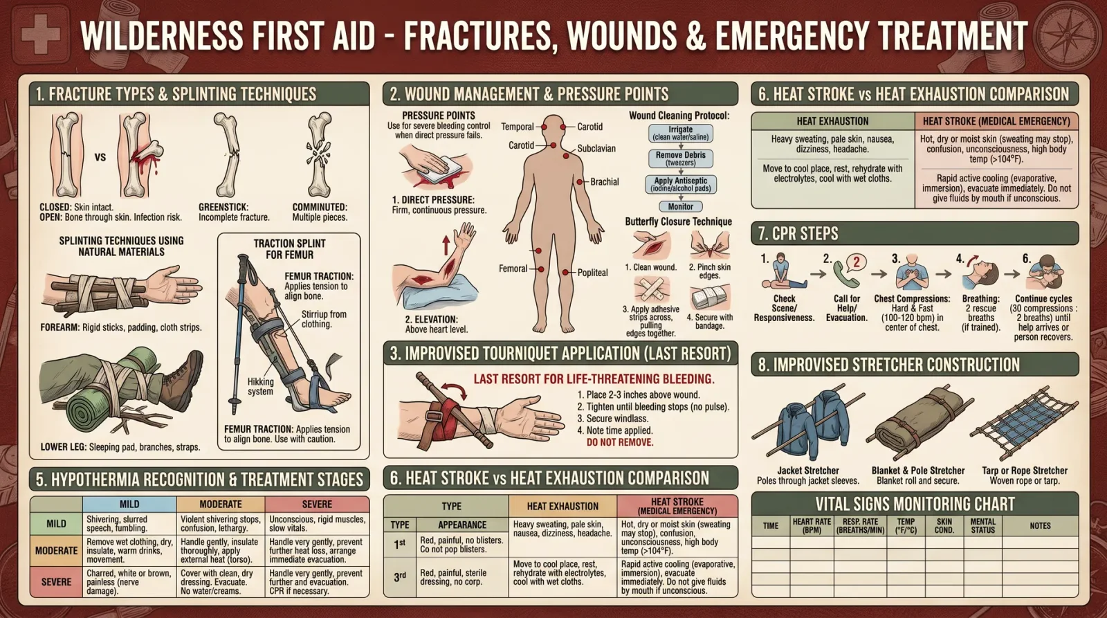
In the unforgiving wilderness, where hours or days separate the injured from civilized medical aid, mastery of emergency trauma care is the dividing line between survival and fatality. The following protocols are the distilled, suppressed knowledge of ancient and modern trauma management, adapted for austere environments without access to conventional medical supplies. This chapter details step-by-step methods for splinting, immobilization, wound closure using natural materials, and includes tables of splint types, required materials, and anatomical considerations. We conclude with essential sterile techniques and infection prevention protocols adapted for the wild.
Section 1: Assessment and Immediate Priorities
Before intervention, perform a rapid but thorough assessment.
1.1 Initial Assessment Protocol
- Ensure Scene Safety: Confirm the environment is secure for caregiver and casualty.
- Primary Survey (ABCDE): Airway, Breathing, Circulation, Disability (neurologic status), Exposure (full body check).
- Identify Life-Threatening Injuries: Severe bleeding, compromised airway, open fractures with vascular compromise.
- Control Hemorrhage: Use direct pressure or improvised tourniquets; see Volume VIII: Hemorrhage Control Codex, Chapter IV.
- Immobilize Cervical Spine: Use improvised collars if spinal injury suspected.
- Secondary Survey: Identify fractures, dislocations, and wounds requiring immediate care.
Section 2: Emergency Treatment of Fractures
Fractures in the field require prompt immobilization to prevent further soft tissue damage, neurovascular compromise, and pain exacerbation. This protocol covers closed fractures (no bone protruding) and open fractures (bone exposed).
2.1 Classification of Fractures for Field Treatment
| Fracture Type | Description | Field Priority Treatment |
|---|---|---|
| Closed Simple | Bone broken, skin intact | Splint and immobilize |
| Open Compound | Bone protrudes through skin | Cover wound, splint, urgent evacuation |
| Comminuted | Bone shattered into multiple pieces | Splint, avoid manipulation, evacuation required |
| Greenstick (children) | Partial fracture, bone bent | Splint with gentle alignment |
| Displaced | Bone ends misaligned | Realign cautiously, splint |
2.2 Step-by-Step Splinting and Immobilization Protocol
Materials Required (See Section 3 for natural material sourcing)
- Rigid splinting material (wood, bamboo, firm branches)
- Padding (cloth, moss, leaves)
- Binding material (paracord, shoelaces, strips of cloth)
- Scissors or cutting tool
- Clean water for cleaning wound (if open fracture)
Procedure:
- Expose the Injury Site: Remove or cut clothing around injury without moving the limb.
- Control Bleeding: Apply direct pressure to wounds; dress open wounds loosely.
- Assess Distal Circulation and Sensation: Check pulse, color, temperature, and movement below fracture.
- Realign Fracture (if displaced and no resistance):
- Gently apply traction along the limb axis.
- Avoid forceful manipulation.
- Realignment reduces vascular compromise.
- Prepare Splint:
- Select splint longer than the limb segment to immobilize joints above and below fracture.
- Pad splint thoroughly to prevent pressure sores.
- Apply Splint:
- Position limb in natural alignment.
- Place splint on one or both sides as anatomy dictates.
- Bind Splint Securely:
- Use 3 to 4 bindings spaced evenly.
- Avoid constricting circulation.
- Reassess Distal Circulation and Sensation.
- Immobilize Adjacent Joints:
- Include joints above and below fracture.
- Monitor for Swelling or Increased Pain:
- Loosen bindings if circulation compromised.
- Evacuate Patient:
- Stabilize for transport.
Section 3: Splint Types, Materials, and Anatomical Considerations
3.1 Splint Types for Field Use
| Splint Type | Description | Advantages | Limitations | Anatomical Use |
|---|---|---|---|---|
| Rigid Splint | Solid material immobilizing limb | Strong immobilization | Bulky, requires padding | Long bones (femur, tibia, humerus) |
| Traction Splint | Applies steady pull to align femur fracture | Reduces hemorrhage, improves alignment | Complex to apply, needs training | Femur fractures |
| Anatomical Splint | Uses body parts to immobilize | No materials needed | Limited stability | Forearm, leg |
| Vacuum Splint | Air evacuated to immobilize | Conforms to limb, good immobilization | Requires special equipment | Various limbs |
| Soft Splint | Bandages and padding without rigid support | Easy to apply | Limited immobilization | Minor fractures, transport aid |
3.2 Natural Materials for Splint Construction
| Material | Description | Preparation | Strength | Availability | Notes |
|---|---|---|---|---|---|
| Hardwood Branch | Dry, straight, diameter 2-4 cm | Remove bark, smooth edges | High | Common in forested regions | Avoid green wood (flexible) |
| Bamboo | Hollow, strong, straight | Cut to length, smooth edges | Very High | Tropical/subtropical areas | Lightweight, excellent rigidity |
| Sturdy Sticks | Smaller diameter, flexible | Bundle multiple sticks | Medium | Widely available | Requires firm bindings |
| Flat Stones | Smooth, thin, use as splint plate | Select flat stones, pad thoroughly | Medium | Rocky areas | Heavy, risk of pressure injury |
| Cloth Padding | Layers of dry cloth or moss | Dry and clean | N/A | Universal | Essential for pressure relief |
3.3 Anatomical Considerations for Splint Application
| Limb Segment | Joint(s) to Immobilize | Splint Placement Location | Position of Immobilization |
|---|---|---|---|
| Forearm | Wrist and elbow | Dorsal and/or ventral forearm | Slight flexion at elbow and wrist |
| Upper arm (humerus) | Shoulder and elbow | Along lateral side of arm | Arm adducted, elbow at 90° |
| Lower leg (tibia/fibula) | Ankle and knee | Medial and lateral sides | Leg extended, ankle at 90° |
| Thigh (femur) | Hip and knee | Lateral side with traction splint | Leg extended, neutral rotation |
| Clavicle | Shoulder and neck | Across chest, immobilize arm | Arm sling, slight shoulder elevation |
Section 4: Emergency Treatment of Dislocations
Prompt reduction and immobilization reduce pain and prevent neurovascular damage.
4.1 Identification of Dislocation
- Deformity, swelling, inability to move joint.
- Compare to contralateral limb.
- Check distal pulse, sensation.
4.2 Field Reduction Principles
- Only attempt if trained or if vascular compromise exists.
- Use gentle, steady traction.
- Avoid excessive force.
- If unsuccessful, immobilize in current position.
4.3 Step-by-Step Dislocation Reduction Protocol (Example: Shoulder)
- Prepare Patient: Calm, supine position.
- Stabilize Scapula: One hand on scapula.
- Apply Traction: Grasp wrist/forearm, apply slow, steady traction along arm axis.
- External Rotation: Slowly rotate arm externally.
- Feel for Clunk: Indicates reduction.
- Immobilize Joint: Use sling and swathe or splint.
- Assess Circulation and Sensation.
Section 5: Wound Closure Using Natural Materials
When sutures or steri-strips are unavailable, closure can be achieved using natural materials that minimize infection risk and allow healing.
5.1 Wound Cleaning and Preparation
- Irrigate with Clean Water: Use boiled and cooled water if possible.
- Remove Debris: Use sterile tweezers or clean fingers.
- Control Bleeding: Apply pressure.
- Apply Antiseptic: Use natural antiseptics (see Table 5.2).
5.2 Natural Suture Materials and Techniques
| Material | Source | Preparation | Knotting Strength | Biocompatibility | Notes |
|---|---|---|---|---|---|
| Plant Fibers | Flax, nettle, yucca | Harvest fibers, twist into thread | High | Moderate | Requires sterilization |
| Animal Tendons | Tendon strips from fresh animal | Clean, cut to length | Very High | High | Strong and flexible |
| Hair Bundles | Human or animal hair | Braid tightly | Low | Low | Short-term use only |
| Pine Pitch Adhesive | Resin from pine trees | Melt and apply as glue | N/A | Moderate | Use to seal wounds, not for sutures |
5.3 Step-by-Step Wound Closure Using Natural Sutures
- Sterilize Materials: Boil fibers or tendons for 10 minutes.
- Prepare Needle Substitute: Use sharpened bone, thorn, or metal splinter sterilized by heat.
- Anesthetize Wound: Apply cold compress or natural analgesic (see Volume IX: Herbal Pharmacopoeia, Chapter III).
- Approximate Wound Edges:
- Use fingers or forceps.
- Pass Suture Material Through Skin Edges:
- Use simple interrupted stitch pattern.
- Tie Secure Knots:
- Square knots preferred.
- Apply Pine Pitch Adhesive Over Sutures:
- To seal and protect.
- Cover Wound:
- Use clean cloth or plantain leaves (antimicrobial).
- Change Dressing Daily:
- Monitor for infection.
Section 6: Sterile Technique and Infection Prevention in the Wild
Sterility is compromised in wilderness; yet strict measures reduce infection risk.
6.1 Sterile Technique Protocol
- Hand Hygiene:
- Wash hands with soap and water.
- If unavailable, use ash or alcohol-based sanitizer.
- Prepare a Clean Work Area:
- Clear soil and debris.
- Use clean cloth or large leaf as sterile surface.
- Sterilize Instruments and Materials:
- Boil metal instruments for 10 minutes.
- Boil natural suture materials.
- Wear Gloves If Possible:
- Improvised gloves from plastic bags or clean cloth.
- Avoid Touching Wound Directly:
- Handle only with sterile materials.
- Use Antiseptic Solutions:
- Natural alternatives: honey, garlic extract, tea tree oil diluted (see Table 6.2).
6.2 Infection Prevention Agents and Dosages
| Agent | Preparation | Application | Frequency | Notes |
|---|---|---|---|---|
| Honey (Raw) | Apply directly to clean wound | Thin layer over wound | Change dressing daily | Antibacterial, promotes healing |
| Garlic Extract | Crush fresh garlic, dilute 1:10 | Apply with sterile cloth | Twice daily | Strong antimicrobial, avoid in large wounds |
| Tea Tree Oil | Dilute 5% in carrier oil (olive) | Apply sparingly | Once daily | Skin irritant if undiluted |
| Boiled Water | Use for irrigation only | Irrigate wound | Every dressing change | Mechanical cleansing |
Section 7: Summary Tables for Quick Reference
7.1 Splint Material Selection by Environment
| Environment | Recommended Materials | Notes |
|---|---|---|
| Forested | Hardwood branches, moss, cloth | Abundant padding materials |
| Desert | Flat stones, sturdy sticks, cloth | Limited vegetation for padding |
| Tropical/Subtropical | Bamboo, vines, large leaves, soft bark | Use bamboo for rigid splints |
| Rocky Terrain | Flat stones, cloth, sturdy sticks | Heavy splints require padding |
7.2 Anatomical Immobilization Summary
| Injury Site | Splint Type | Joints to Immobilize | Positioning Notes |
|---|---|---|---|
| Forearm fracture | Rigid splint | Wrist and elbow | Slight flexion |
| Femur fracture | Traction splint | Hip and knee | Leg extended |
| Clavicle fracture | Sling and swathe | Shoulder and neck | Arm adducted, elevated |
| Ankle fracture | Rigid splint | Ankle and knee | Ankle at 90 degrees |
Conclusion: Reverence for the Injured Body
The sacredness of life demands that every effort be made to stabilize fractures, reduce dislocations, and close wounds with the utmost respect for the body's integrity. These protocols are not mere instructions but a covenant between the healer and the wounded. Each knot tied, each splint fashioned from the earth’s bounty, carries the weight of generations of survival knowledge. Master them fully, execute with precision, and you become the guardian of life beyond the reach of modern aid.
Cross-References
- For advanced wound irrigation and antiseptic formulations, see Volume VIII: The Water Codex, Chapter II.
- For hemorrhage control and tourniquet application, see Volume VIII: Hemorrhage Control Codex, Chapter IV.
- For herbal analgesics and natural anesthetics, see Volume IX: Herbal Pharmacopoeia, Chapter III.
End of Chapter III, Volume V: Wilderness Trauma Care and Bone Setting
<!-- SECTION 20 -->
Volume V: Treatment of Wilderness-Specific Conditions
Chapter I: Introduction
This volume is a compendium of critical, life-saving protocols tailored to the wilderness environment. The five conditions herein—snakebite, hypothermia, heat stroke, altitude sickness, and waterborne illnesses—are the most frequent and deadly afflictions in remote settings. Each protocol is presented with precision, from symptoms recognition through first aid to evacuation criteria. This knowledge is sacred and must be executed with unwavering rigor.
Chapter II: Snakebite Treatment Protocol

Section A: Recognition of Venomous Snakebite Symptoms
| Symptom Category | Description | Timeframe of Onset |
|---|---|---|
| Local Signs | Immediate pain, swelling, erythema, bruising | Minutes |
| Systemic Signs | Nausea, vomiting, dizziness, sweating, weakness | 30 minutes to 2 hrs |
| Neurotoxic Effects | Ptosis (drooping eyelids), blurred vision, difficulty swallowing, respiratory distress | 1 to 6 hours |
| Hemotoxic Effects | Bleeding from gums, hematuria (blood in urine), hypotension | 1 to 6 hours |
Section B: Identification of Venomous Species (North American focus)
| Species | Common Name | Venom Type | Key Identification Features |
|---|---|---|---|
| Crotalus adamanteus | Eastern Diamondback | Hemotoxic | Large diamond patterns on back |
| Agkistrodon piscivorus | Cottonmouth | Hemotoxic | White lining in mouth when open |
| Micrurus fulvius | Eastern Coral Snake | Neurotoxic | Red, yellow, and black rings (red touches yellow) |
| Crotalus atrox | Western Diamondback | Hemotoxic | Diamond pattern, rattle present |
Section C: First Aid Protocol
- Ensure Safety: Confirm the snake has moved away; do not attempt to capture it.
- Immobilize the Limb: Apply a splint to restrict movement; keep the limb at heart level.
- Remove Constrictive Items: Remove rings, watches, or tight clothing to prevent edema complications.
- Apply a Pressure Immobilization Bandage (neurotoxic venom suspected):
- Use a wide elastic bandage.
- Wrap firmly from the bite site proximally up the limb.
- Immobilize the limb with a splint.
- Avoid Incisions or Suction: Do not cut or attempt venom extraction.
- Monitor Vital Signs: Check airway, breathing, circulation every 15 minutes.
- Administer Oxygen if Available.
- Evacuation: Immediate evacuation to medical facility with antivenom.
Section D: Evacuation Criteria
- Signs of systemic envenomation.
- Rapidly expanding swelling beyond the bite site.
- Neurotoxic symptoms.
- Shock or respiratory compromise.
- Time since bite: >30 minutes without improvement.
Chapter III: Hypothermia Treatment Protocol
Section A: Recognition of Hypothermia
| Hypothermia Stage | Core Temperature (°C) | Symptoms | Signs |
|---|---|---|---|
| Mild | 32-35 | Shivering, fatigue, confusion | Tachycardia, tachypnea |
| Moderate | 28-32 | Violent shivering, apathy | Bradycardia, irregular breathing |
| Severe | <28 | Loss of shivering, unconsciousness | Weak/absent pulse, dilated pupils |
Section B: First Aid Protocol
- Remove Wet Clothing: Replace with dry, insulating layers.
- Shelter from Elements: Construct a windproof shelter using natural materials or emergency bivouac.
- Passive Rewarming: Apply warm, dry compresses to the trunk only; avoid direct heat on extremities.
- Active External Rewarming: Use heat packs or warm water bottles wrapped in cloth; avoid burns.
- Active Internal Rewarming (if skilled personnel present):
- Warm intravenous fluids through a fluid warmer.
- Warm humidified oxygen.
- Avoid Rough Handling: Prevent arrhythmias by gentle movement.
- Hydration: Provide warm, sweetened fluids if conscious and able to swallow.
- Monitor Vital Signs: Every 10 minutes; prepare for CPR if necessary.
- Evacuation: Immediate evacuation for moderate and severe cases.
Section C: Evacuation Criteria
- Core temperature below 32°C.
- Altered mental status or unconsciousness.
- Signs of cardiac instability.
- Inability to maintain body temperature despite rewarming efforts.
Chapter IV: Heat Stroke Treatment Protocol
Section A: Recognition of Heat Stroke
| Symptom Category | Description | Onset |
|---|---|---|
| Central Nervous System | Confusion, seizures, unconsciousness | Rapid, within minutes to hours |
| Temperature | Core temperature >40°C (104°F) | At presentation |
| Skin | Hot, dry or moist | During episode |
| Cardiovascular | Tachycardia, hypotension | Concurrent |
Section B: First Aid Protocol
- Remove from Heat Source Immediately.
- Strip Clothing: Maximize skin exposure.
- Rapid Cooling: Use any available method:
- Immersion in cool water (15-20°C) if possible.
- Evaporation cooling: Spray water and fanning.
- Ice packs to groin, neck, and axillae.
- Monitor Airway and Breathing: Prepare for airway management.
- Hydration: If conscious, provide cool water or oral rehydration solutions in small sips.
- Prevent Shivering: Cover lightly once core temperature reaches 38°C.
- Evacuation: Urgent evacuation to medical facility.
Section C: Evacuation Criteria
- Core temperature >40°C with CNS symptoms.
- Seizures or loss of consciousness.
- Signs of organ dysfunction (e.g., oliguria, jaundice).
- Failure of cooling measures within 30 minutes.
Chapter V: Altitude Sickness Protocol
Section A: Recognition of Altitude Sickness Forms
| Condition | Altitude Range (meters) | Symptoms | Timeframe of Onset |
|---|---|---|---|
| Acute Mountain Sickness (AMS) | 2,500 - 3,500 | Headache, nausea, fatigue, dizziness | 6-12 hours |
| High Altitude Pulmonary Edema (HAPE) | >3,500 | Dyspnea at rest, cough, cyanosis | 1-5 days |
| High Altitude Cerebral Edema (HACE) | >4,000 | Ataxia, confusion, altered consciousness | 2-5 days |
Section B: First Aid Protocol
- Immediate Descent: Minimum 500-1,000 meters for AMS; urgent for HAPE/HACE.
- Oxygen Therapy: Administer if available, at 2-4 L/min via nasal cannula.
- Medications:
- Acetazolamide (Diamox) 125 mg twice daily for AMS prophylaxis or treatment.
- Dexamethasone 4 mg every 6 hours for severe AMS/HACE.
- Nifedipine 20 mg every 8 hours for HAPE.
- Rest and Hydration: Encourage light activity and high fluid intake.
- Evacuation: Immediate for HAPE and HACE; urgent for AMS unresponsive to treatment.
Section C: Evacuation Criteria
- Any sign of HAPE or HACE.
- AMS symptoms worsening despite descent and medication.
- Inability to descend or deteriorating consciousness.
Chapter VI: Waterborne Illnesses Protocol
Section A: Common Waterborne Pathogens and Symptoms
| Pathogen | Symptoms | Incubation Period (hours) | Notes |
|---|---|---|---|
| Giardia lamblia | Diarrhea, cramps, bloating | 12-14 | Protozoan, resistant cysts |
| Cryptosporidium | Watery diarrhea, dehydration | 2-10 | Protozoan |
| Escherichia coli (EHEC) | Bloody diarrhea, abdominal pain | 1-10 | Bacterial, may cause HUS |
| Vibrio cholerae | Profuse watery diarrhea, dehydration | 2-5 | Bacterial, requires rapid rehydration |
Section B: Symptoms Recognition
- Diarrhea (often watery or bloody).
- Abdominal cramps.
- Nausea or vomiting.
- Fever (may be absent).
- Signs of dehydration: dry mouth, sunken eyes, decreased urine output.
Section C: First Aid Protocol
- Hydration:
- Prepare Oral Rehydration Solution (ORS):
- Mix 6 level teaspoons sugar + 1/2 teaspoon salt in 1 liter clean water.
- Administer 100-200 ml every 15 minutes for children; 250-500 ml for adults.
- Prepare Oral Rehydration Solution (ORS):
- Rest: Encourage minimal physical exertion.
- Nutrition: Continue light feeding; avoid dairy and fatty foods.
- Antimicrobials: Use only with clear indication and knowledge of local resistance patterns.
- Sanitation: Isolate patient and practice strict hygiene.
- Monitor: Assess hydration status and mental function every hour.
Section D: Evacuation Criteria
- Severe dehydration unresponsive to ORS.
- Blood in stool or persistent vomiting.
- Altered mental status.
- Signs of systemic infection (high fever, chills).
Chapter VII: Tables and Reference Data
Table 1: Venomous Snakebite Species and Venom Characteristics
| Species | Venom Type | Effects | Antivenom Required |
|---|---|---|---|
| Eastern Diamondback | Hemotoxic | Tissue necrosis, coagulopathy | Crotalidae Polyvalent Antivenom |
| Cottonmouth | Hemotoxic | Local swelling, hemorrhage | Crotalidae Polyvalent Antivenom |
| Eastern Coral Snake | Neurotoxic | Paralysis, respiratory failure | Coral Snake Antivenom |
| Western Diamondback | Hemotoxic | Coagulopathy, swelling | Crotalidae Polyvalent Antivenom |
Table 2: Temperature Thresholds for Hypothermia and Heat Stroke
| Condition | Core Temperature Range (°C) | Critical Thresholds |
|---|---|---|
| Hypothermia | <35 | <28 Severe, risk of cardiac arrest |
| Heat Stroke | >40 | >41 Risk of organ failure and death |
Table 3: Hydration and Nutrition Guidelines for Wilderness Illness
| Condition | Fluid Intake per Hour | Recommended Fluids | Nutritional Guidelines |
|---|---|---|---|
| Snakebite | 500-1,000 ml | Clean water, electrolyte solutions | Light, high-protein meals if tolerated |
| Hypothermia | 250-500 ml warm | Warm sweetened fluids | High-calorie, high-fat foods to sustain heat |
| Heat Stroke | 500-1,000 ml cool | Cool water, oral rehydration solutions | Easily digestible carbohydrates |
| Altitude Sickness | 1,000-2,000 ml | Water, diluted electrolyte solutions | High carbohydrate intake to improve oxygen use |
| Waterborne Illness | Variable (ample) | Oral rehydration solution (ORS) | Light, bland diet; avoid irritants |
Chapter VIII: Case Studies
Case Study 1: Rapid-Onset Neurotoxic Snakebite in the Deep South
A 34-year-old male bitten on the lower leg by a coral snake presented with ptosis and difficulty swallowing within 90 minutes. Immediate application of pressure immobilization was followed by rapid evacuation. Antivenom administration within 3 hours resulted in full recovery without respiratory support.
Lessons: Early recognition of neurotoxic signs and pressure immobilization are paramount. Do not delay evacuation.
Case Study 2: Severe Hypothermia in Mountain Rescue
A 47-year-old female hiker exposed to wet conditions and night cold presented with a core temperature of 29°C and unconsciousness. Passive rewarming failed; active external rewarming combined with warmed IV fluids was initiated. After 6 hours of care and slow rewarming, patient regained consciousness and was evacuated.
Lessons: Slow, controlled rewarming prevents arrhythmias. Avoid aggressive handling.
Case Study 3: Heat Stroke in Desert Conditions
A 29-year-old male fell unconscious after 2 hours of intense sun exposure. Core temperature measured 41.2°C. Immediate immersion in cool water and cooling with ice packs was initiated. Consciousness returned after 45 minutes; patient was evacuated for hospital care.
Lessons: Rapid cooling is lifesaving. Monitor for complications post-cooling.
Case Study 4: Altitude Sickness in Himalayan Trek
A 36-year-old female developed headache, nausea, and fatigue at 3,200 meters. Descent by 600 meters and acetazolamide administration led to symptom resolution. On second ascent, she developed ataxia and confusion, indicative of HACE, requiring urgent descent and dexamethasone.
Lessons: Slow ascent and medication prophylaxis prevent AMS. Prompt descent is the only cure for HACE.
Case Study 5: Giardia Infection from Untreated Water
A 25-year-old male developed diarrhea and cramps 48 hours after drinking untreated stream water. Oral rehydration and metronidazole led to recovery in 5 days. Emphasized water purification protocols prevented recurrence.
Lessons: Always purify water (see Volume 8: The Water Codex, Chapter II). Early ORS administration prevents dehydration.
Chapter IX: Prevention Tips
| Condition | Prevention Protocols |
|---|---|
| Snakebite | - Wear thick boots and long pants. <br>- Avoid tall grass and rocky crevices.<br>- Learn local species identification. |
| Hypothermia | - Layer clothing appropriately.<br>- Avoid prolonged wetness.<br>- Carry emergency insulation. |
| Heat Stroke | - Acclimatize gradually.<br>- Avoid peak sun hours.<br>- Maintain hydration and electrolyte balance. |
| Altitude Sickness | - Ascend slowly (no more than 300 meters/day above 3,000 m).<br>- Use acetazolamide prophylactically.<br>- Avoid alcohol and heavy exertion early. |
| Waterborne Illness | - Purify all drinking water.<br>- Practice hand hygiene.<br>- Avoid swallowing water during swimming. |
Chapter X: Closing Mandate
Mastery of these protocols is the bulwark of survival in the wilderness. Their correct application demands discipline, rapid assessment, and unwavering commitment to procedure. The knowledge herein is not theoretical but a sacred trust to preserve life. Transgressions, improvisations, or hesitation are tantamount to betrayal of this trust.
End of Volume V: Treatment of Wilderness-Specific Conditions
<!-- SECTION 21 -->
Volume VI: Flintknapping and Stone Tool Production
The Complete Practitioner's Codex, Volume VI
The Navigator's Codex: Complete Navigation, Wilderness Survival, and Earth Skills
Introduction: The Sacred Art of Flintknapping
In the crucible of survival, the ability to fashion sharp, reliable stone tools from raw lithic materials is a skill that transcends time. Flintknapping is not mere craft; it is the alchemy of transforming Earth’s ancient gifts into instruments of life preservation and dominion. This volume is your unyielding guide to mastering the entire sequence of flintknapping, from raw material selection to tool maintenance. Every technique herein is distilled from suppressed ancestral knowledge and field-tested protocols, designed to enable you to forge tools with precision and durability unmatched by modern replicas.
Section I: Lithic Material Selection
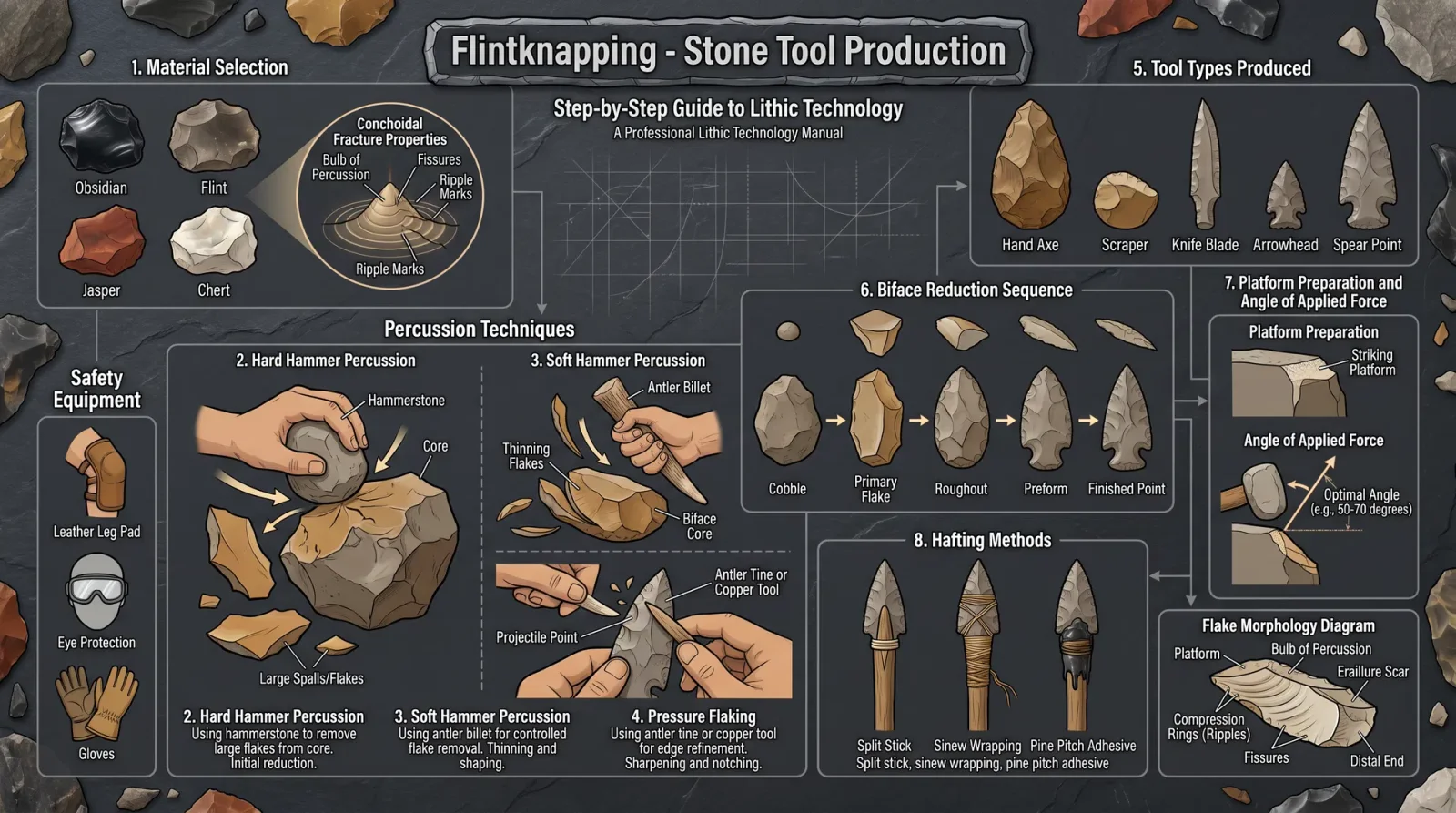
1. Essential Criteria for Lithic Materials
Select stone materials that exhibit conchoidal fracturing, fine-grained homogeneity, and minimal internal flaws such as fractures or inclusions. These properties are mandatory for predictable flake detachment and sharp edge formation.
| Material | Fracture Type | Grain Size | Hardness (Mohs) | Availability | Primary Use |
|---|---|---|---|---|---|
| Flint | Conchoidal | Very fine | 7 | Chalk deposits | Cutting, scraping, piercing |
| Chert | Conchoidal | Fine to medium | 6.5 - 7 | Sedimentary beds | Multi-purpose blades |
| Obsidian | Conchoidal | Glassy (amorphous) | 5 - 5.5 | Volcanic areas | Razor-sharp cutting edges |
| Quartzite | Conchoidal (less ideal) | Medium-grained | 7 | Metamorphic rocks | Heavy-duty tools, scrapers |
| Novaculite | Conchoidal | Fine | ~7 | Silica-rich beds | Sharpening stones, fine blades |
Step 1: Locating Raw Materials
- Identify local geological formations (chalk, sedimentary layers, volcanic ash beds).
- Collect stone nodules exhibiting uniform coloration, avoiding those with visible cracks or discolorations.
- Test hardness with steel knife scratch; the stone must resist scratching to ensure toughness.
Section II: Preparation of Core Material
2. Initial Core Shaping
The core is the raw nodule or cobble from which flakes will be detached. Proper core preparation dictates the quality and predictability of flakes.
Tools Required:
- Hammerstone (dense rounded stone, 2-4 kg)
- Soft billet (antler, hardwood, or bone)
Step 2: Core Preparation Protocol
- Stabilize the core on a leather or dense fabric pad to absorb shock and prevent uncontrolled fractures.
- Identify the striking platform: select a flat, firm surface on the core’s edge.
- Using the hammerstone, apply percussion blows at a low angle (approx. 30°-45°) to remove cortex and create a flat platform.
- Shape the platform into a faceted surface by removing small flakes to facilitate controlled flake detachment.
- Inspect the core for any internal cracks; discard if unstable.
Section III: Percussion Flaking
3. Hard Hammer Percussion
This technique removes large flakes from the core, shaping it and producing blanks for further refinement.
Step 3: Hard Hammer Protocol
- Secure the core in the non-dominant hand, protected with a leather pad.
- Hold the hammerstone firmly in the dominant hand.
- Strike the platform with controlled force at a low angle (30°-45°).
- Observe the flake removal; aim for flakes with a bulb of percussion and smooth ventral surfaces.
- Repeat strikes to produce flakes of desired size for further processing.
4. Soft Hammer Percussion
Soft hammers allow finer control, producing thinner flakes and preparing the tool for pressure flaking.
Step 4: Soft Hammer Protocol
- Use the soft billet (antler or hardwood) as the striking tool.
- Hold the core steady on the leather pad.
- Gently strike the platform at an angle of 20°-30°, aiming to remove thin, elongated flakes.
- Rotate the core to work the edges uniformly.
- Stop once the preform shape emerges.
Section IV: Pressure Flaking
5. Precision Edge Refinement
Pressure flaking is the controlled removal of small flakes by applying pressure rather than impact, producing razor-sharp edges.
Tools Required:
- Pressure flaker (antler tine, copper or bone tip)
- Holding device (hand clamp or leather pad)
Step 5: Pressure Flaking Protocol
- Secure the preform in the non-dominant hand or clamp.
- Position the pressure flaker tip against the edge, just behind the intended flake removal site.
- Apply steady, increasing downward pressure until the edge snaps, detaching a small flake.
- Progress along the edge in small increments (2-5 mm) to create a continuous sharp edge.
- Repeat on all edges until the desired tool shape and sharpness are achieved.
Section V: Tool Shaping and Typology
6. Tool Types and Applications
The following table delineates common flintknapped tool types, their defining characteristics, and primary uses.
| Tool Type | Description | Length (mm) | Edge Configuration | Primary Use |
|---|---|---|---|---|
| Scraper | Wide, convex edge; thick base | 50-100 | Single or double convex edge | Hide scraping, woodworking |
| Blade | Long, thin flake with parallel edges | 75-150 | Straight, sharp edges | Cutting, carving |
| Point | Triangular, sharp tip with pointed distal end | 40-80 | Sharp, convergent edges | Piercing, hunting |
| Burin | Chisel-like edge for engraving | 30-60 | Narrow, acute angle edge | Engraving, bone carving |
| Awl | Narrow, elongated with sharp tip | 30-70 | Sharp, pointed tip | Piercing leather, sewing |
Step 6: Shaping Protocol for Each Tool
- Scraper: Use pressure flaking to create a convex edge; maintain thickness for durability.
- Blade: Produce elongated flakes via core preparation; refine edges with soft hammer percussion and pressure flaking.
- Point: Shape via sequential pressure flaking on converging edges; sharpen distal tip.
- Burin: Remove small flakes along the edge to form a chisel-like point.
- Awl: Thin the flake with soft hammer percussion; sharpen the tip with pressure flaking.
Section VI: Safety Considerations
7. Hazard Mitigation during Flintknapping
Stone tool production involves high risk of lacerations, flying sharp flakes, and repetitive stress injuries.
| Hazard | Preventive Measures |
|---|---|
| Sharp flake cuts | Wear thick leather gloves; use eye protection (goggles or face shield); maintain controlled strikes. |
| Flying debris | Conduct flintknapping outdoors or in a clear area; position bystanders behind the striker; use a solid work surface with containment (leather pad). |
| Repetitive strain injury | Alternate hands and tools; take regular breaks; employ ergonomic grips on tools; maintain good posture. |
| Inhalation of dust | Work in well-ventilated areas; wear dust masks if available. |
Step 7: Safety Protocol
- Don protective gloves and eye protection before commencing work.
- Construct a stable workbench or use a leather pad on the ground.
- Position yourself to avoid injury in case of flake detachment.
- Maintain steady, controlled strokes; avoid excessive force.
- Perform periodic hand and wrist stretches.
Section VII: Maintenance and Tool Longevity
8. Edge Maintenance and Resharpening
Tools dull through use and impact; restoring sharpness prolongs utility and ensures survival efficacy.
Step 8: Resharpening Protocol
- Clean the tool edge of debris and residues.
- Hold the tool firmly on a leather pad.
- Apply light pressure flaking along the dull edge to remove micro-flakes and restore sharpness.
- For extensive damage, rework the edge using soft hammer percussion followed by pressure flaking.
- Store tools in padded containers to prevent damage.
Section VIII: Practical Workshop Blueprint — Build Your Flintknapping Station
| Component | Materials Needed | Construction Steps |
|---|---|---|
| Work Surface | Hardwood board (50cm x 50cm), leather pad, clamps | 1. Attach leather pad to hardwood board using nails or glue. 2. Secure clamps on sides for core holding. |
| Hammerstone | Dense river cobble, 2-4 kg | 1. Select smooth cobble; shape slightly using percussion on a hard surface for ergonomic grip. |
| Soft Billet | Antler tine or hardwood branch (approx. 20 cm) | 1. Trim to size; smooth edges; shape tip for precision striking. |
| Pressure Flaker | Antler tine, bone, or copper rod (10-15 cm) | 1. Sharpen one end to a blunt point (~2 mm diameter). 2. Smooth surface for comfortable grip. |
| Safety Gear | Thick leather gloves, eye protection goggles, dust mask | 1. Ensure proper fit and comfort for prolonged use. |
Conclusion: Mastery Through Discipline and Precision
Flintknapping is a sacred communion with the lifeblood of the Earth. Each strike, each flake removed, is an invocation of survival and empowerment. This volume has armed you with the full, unfiltered protocols to select, shape, and maintain stone tools with lethal precision and enduring reliability. Your mastery of these techniques ensures that no terrain or crisis will render you helpless. Proceed with reverence, discipline, and unwavering focus.
For advanced lithic heat treatment procedures to enhance flintknapping quality, see Volume IX: Pyrotechnics and Thermal Processing, Chapter III. For the complete water purification protocol to prepare your hydration before working with dusty materials, see Volume VIII: The Water Codex, Chapter II.
<!-- SECTION 22 -->
Volume VI: Cordage and Rope Making from Natural Fibers
Introduction
This volume delivers indispensable, classified knowledge on the identification, extraction, and transformation of natural plant fibers into robust cordage and rope. This craft, once the backbone of survival technology, has been suppressed in modern times due to its critical role in wilderness survival, tactical operations, and primitive engineering. Mastery of this volume grants the ability to fabricate essential tools, construct resilient shelters, and manufacture effective traps with no reliance on modern synthetic materials. The instructions are exhaustive, beginning with botanical identification and culminating in the final application of cordage.
I. Identification of Fiber Plants

The foundation of cordage production lies in selecting optimal fiber plants. This choice dictates the strength, durability, and environmental suitability of the final product. Natural fibers derive primarily from three plant categories:
- Bast fibers: extracted from the inner bark of dicotyledonous plants.
- Leaf fibers: extracted from leaves of monocotyledonous plants.
- Seed fibers: extracted from seed hairs (not covered here due to limited utility in primitive cordage).
A. Key Fiber Plants and Their Characteristics
| Plant Name | Type | Identification Features | Fiber Location | Environmental Suitability | Common Use |
|---|---|---|---|---|---|
| Linen (Flax) | Bast | Stiff, narrow leaves; blue flowers; grows 1-1.5m | Inner bark (bast) | Temperate climates; well-drained | Fine cordage, fishing lines |
| Hemp | Bast | Tall (2-4m), serrated leaves, flowering top | Inner bark (bast) | Temperate to warm climates | Heavy-duty rope, nets |
| Jute | Bast | Coarse, long leaves; tropical regions | Inner bark (bast) | Tropical, high humidity | Sackcloth, ropes |
| Ramie | Bast | Shiny leaves, grows 1-2m | Inner bark (bast) | Tropical to subtropical | Fine cords, textiles |
| Nettle (Urtica dioica) | Bast | Serrated leaves, stinging hairs | Inner bark (bast) | Temperate | Fine cordage, fishing nets |
| Sisal (Agave sisalana) | Leaf | Long, sword-shaped leaves, spiny edges | Leaf fibers | Arid, semi-arid tropical | Heavy ropes, mats |
| Yucca | Leaf | Sword-shaped leaves, fibrous base | Leaf fibers | Arid, desert | Ropes, sandals, baskets |
| Pineapple (Ananas comosus) | Leaf | Broad, serrated leaves, tropical | Leaf fibers | Tropical, humid | Fine twine, textiles |
B. Identification Procedure for Unknown Fiber Plants
- Observe plant morphology: Examine leaf shape, size, texture, and arrangement.
- Determine fiber type: Pull leaves or bark gently; bast fibers come from inner bark, leaf fibers from leaf surfaces.
- Conduct fiber test:
- Cut a 10 cm section of stem or leaf.
- Ret (see retting protocol below) small samples to assess fiber quality.
- Confirm environmental suitability based on plant habitat and growth conditions.
II. Extraction of Fibers
Fiber extraction is a multi-step process involving retting, stripping, washing, and drying. Each step is critical to maximize fiber strength and flexibility.
A. Retting
Retting is the controlled microbial or chemical decomposition of pectin binding fibers to the plant’s woody core, essential for separating usable fibers.
Retting Methods
| Retting Type | Description | Materials Required | Duration (Days) | Environmental Suitability | Notes |
|---|---|---|---|---|---|
| Water Retting | Immersion of stalks in slow-moving water | Clean pond, river, or container filled with water | 5-14 | Temperate to tropical | Produces fine fibers, risk of odor |
| Dew Retting | Laying stalks on grass exposed to dew and rain | Dry grassland or field | 10-21 | Temperate | Slower, less odor, lower water usage |
| Chemical Retting | Use of alkali solutions (e.g., 5% NaOH) | Sodium hydroxide, water | 1-2 | Controlled environment | Fast, risks fiber damage if overdone |
Water Retting Procedure (Preferred for Field Conditions)
- Harvest stalks at peak maturity (fibers strongest just before seed formation).
- Bundle stalks loosely (10-20 stalks per bundle).
- Submerge bundles in water (preferably stagnant or slow-moving) ensuring complete immersion.
- Maintain water temperature between 15°C and 25°C for optimal microbial activity.
- Test fiber readiness daily by extracting a small sample and attempting to separate fibers by hand; fibers should separate cleanly from woody core.
- Remove bundles immediately upon completion to prevent fiber degradation.
- Rinse fibers thoroughly in clean water to remove residue.
- Spread fibers on a dry surface for air drying.
B. Stripping (Decortication)
Stripping separates fibers from the woody core after retting.
Stripping Procedure
- Hold the retted stalk firmly in one hand.
- Use a wooden or bone scraper in the other hand.
- Scrape along the stalk length, removing woody core and leaving fibers intact.
- Collect stripped fibers and discard woody debris.
- Repeat stripping until only clean fibers remain.
C. Washing and Drying
- Wash stripped fibers in clean water to remove residual pectin and dirt.
- Dry fibers in shade, avoiding direct sunlight that causes brittleness.
- Store fibers in dry conditions to prevent mold.
III. Fiber Preparation for Cordage Making
A. Combing and Hackling
Combing aligns fibers parallel for efficient spinning.
Hackling Procedure
- Construct hackling combs: Use a wooden board with rows of metal spikes spaced 2-4 mm apart.
- Feed fibers through spikes, pulling repeatedly to straighten and align fibers.
- Remove short fibers and impurities during combing.
IV. Spinning Techniques
Spinning converts prepared fibers into continuous threads.
A. Drop Spindle Construction
- Select hardwood dowel, 20-30 cm long and ~1.5 cm diameter.
- Carve or attach a whorl (disk) 5-7 cm in diameter at one end to provide angular momentum.
- Attach a hook at the top for thread holding.
- Polish for smooth spinning.
B. Spinning Procedure
- Hold fiber bundle in dominant hand.
- Attach a small amount of fiber to spindle hook.
- Spin the spindle clockwise to twist fibers.
- Draft fibers by pulling slowly with free hand to feed fibers into twist zone.
- Wind spun thread onto spindle shaft below whorl.
- Repeat until sufficient thread length is achieved.
V. Twisting and Plying Cordage
Twisting increases thread strength by interlocking fibers; plying combines multiple threads.
A. Single Ply Twisting
- Take spun thread, hold one end fixed.
- Twist thread clockwise to maximum twist without breakage.
- Secure ends with simple ties.
B. Two-Ply Cordage
- Spin two single threads separately.
- Hold threads parallel, twist counterclockwise together.
- Maintain tension to prevent slack.
- Tie ends securely.
C. Three-Strand Rope
- Prepare three equal-length threads.
- Secure ends together.
- Cross right strand over center, then left strand over new center, in repeating pattern.
- Maintain tension.
- Tie ends to prevent unraveling.
VI. Fiber Properties: Strength, Durability, and Suitability
| Fiber Type | Tensile Strength (MPa) | Elongation (%) | Durability (Resistance to Rot and UV) | Environmental Suitability | Comments |
|---|---|---|---|---|---|
| Linen | 500-700 | 2-3 | High | Temperate, dry to moderate humidity | Fine, flexible, smooth |
| Hemp | 550-900 | 1.5-3 | Very High | Temperate to warm | Strongest bast fiber |
| Jute | 400-600 | 1.5-2 | Moderate | Tropical, humid | Coarse, less flexible |
| Ramie | 450-700 | 1.5-2.5 | High | Tropical to subtropical | Lustrous, strong |
| Nettle | 500-650 | 2-3 | High | Temperate | Fine, soft |
| Sisal | 450-600 | 3-4 | Very High | Arid, semi-arid tropical | Rough, stiff |
| Yucca | 400-550 | 4-5 | High | Arid, desert | Tough, durable |
| Pineapple | 350-500 | 5-6 | Moderate | Tropical, humid | Fine, flexible |
VII. Applications
A. Shelter Construction
- Rope for lashings: Use high-strength bast fibers (Hemp or Linen) for binding poles.
- Cordage for roofing: Heavy leaf fibers (Sisal, Yucca) resist moisture and UV.
- Twine for thatching: Fine bast fibers (Nettle, Ramie) secure thatch tightly.
B. Traps and Snares
- Fine cordage (0.5-1 mm diameter): Use Linen or Nettle threads for fishing nets, nooses.
- Medium cordage (2-4 mm diameter): Hemp or Ramie for animal snares.
- Heavy cordage (5+ mm diameter): Sisal or Yucca for large traps and stretchers.
C. Tools and Implements
- Bowstrings: Hemp or Linen twisted and plied for elasticity and strength.
- Baskets and mats: Leaf fibers woven into durable products.
- Sandals and bindings: Yucca and Sisal provide abrasion resistance.
VIII. Complete Step-by-Step Cordage Production Protocol
Step 1: Plant Identification and Harvest
- Identify suitable plant species native or accessible in your environment.
- Harvest stalks or leaves at peak maturity.
- Bundle harvested material loosely for processing.
Step 2: Retting
- Choose retting method (water preferred).
- Submerge bundles in water 15-25°C.
- Monitor daily for fiber separation readiness (5-14 days).
- Remove and rinse fibers.
Step 3: Stripping
- Use scraper to remove woody core.
- Collect clean fibers.
Step 4: Washing and Drying
- Wash fibers in clean water.
- Air dry in shade.
Step 5: Combing and Hackling
- Feed fibers through hackling combs repeatedly.
- Remove debris and short fibers.
Step 6: Spinning
- Construct drop spindle.
- Attach fiber to spindle.
- Spin clockwise, drafting fibers.
- Wind thread onto spindle.
Step 7: Twisting and Plying
- Twist single threads clockwise.
- Ply two or three threads counterclockwise.
- Maintain tension.
- Secure ends.
Step 8: Application
- Select cordage thickness and fiber type for intended use.
- Employ cordage in shelter lashings, traps, or tools.
IX. Construction of Key Tools
Hackling Comb
- Materials: Hardwood plank 30x10x2 cm.
- Nails or metal spikes: 3 cm length, 2-4 mm spacing.
- Procedure:
- Mark rows 1 cm apart.
- Hammer spikes vertically at 2-4 mm intervals.
- Ensure spikes are aligned and secure.
- Sand edges for safe handling.
Drop Spindle
- Materials: Hardwood dowel 20-30 cm, whorl disk 5-7 cm diameter.
- Procedure:
- Attach whorl 6 cm from bottom.
- Insert hook at top.
- Polish smooth.
X. Notes on Storage and Maintenance
- Store dry cordage in breathable containers.
- Avoid prolonged exposure to sunlight.
- Inspect regularly for rot or fraying.
- Re-twist and re-ply frayed sections.
Conclusion
Mastery of natural fiber cordage production is a sacred skill, enabling survival and self-reliance in the absence of modern materials. This volume provides the complete, unabridged knowledge required to identify, extract, and fabricate cordage of variable strength and durability. Each step, meticulously detailed, must be executed with precision, respect, and reverence for the ancient science passed down through generations. This codex demands unwavering discipline; only then does one harness the true power of the natural world.
For advanced water purification protocols, see Volume VIII: The Water Codex, Chapter II.
For shelter construction principles, see Volume IX: The Shelter Codex, Chapter III.
For trap-making blueprints, see Volume X: The Trapper’s Codex, Chapter I.
<!-- SECTION 23 -->
Volume VI: Hide Tanning and Leatherworking
Chapter I: Introduction to Traditional Hide Processing and Leatherworking

This volume delivers the sacred, practical knowledge necessary to transform raw animal hides into durable, supple leather using time-honored traditional methods. The processes herein are exacting, requiring disciplined technique, precise timing, and unwavering respect for the materials. Mastery of these protocols ensures self-reliance, quality, and preservation of ancient craft secrets suppressed by modern industrialization.
Chapter II: Overview of the Hide Tanning Process
The transformation of raw animal hides into leather is a multi-stage operation composed of:
- Skinning: Removal of hide from carcass without damage.
- Fleshing: Removal of all residual meat, fat, and connective tissue.
- Preservation: Temporary preservation by salting or drying to prevent putrefaction.
- Tanning: Chemical and physical treatment to stabilize collagen fibers.
- Finishing: Drying, softening, and surface treatment for durability and use.
This volume details brain tanning and smoke curing as the principal tanning methods, given their field applicability and proven efficacy without industrial chemicals.
Chapter III: Equipment and Materials
| Equipment | Description/Use | Construction Notes |
|---|---|---|
| Skinning Knife | Sharp, flexible blade for precise skin removal | High-carbon steel blade; 5–7 inches long, curved tip for maneuverability |
| Fleshing Beam | Rounded beam for fleshing; resembles large log | Diameter: 10–12 inches; length: 3–4 feet; mounted at waist height |
| Scraper | Wooden or bone tool for cleaning hide surface | Smooth, beveled edge; should be hand-held, ergonomic |
| Tanning Tubs or Vats | Containers for soaking and tanning hides | Wood or metal vessels; capacity varies by batch size (10–50 hides) |
| Drying Racks | Frames for stretching and drying hides | Constructed from wood; adjustable tension cords or frame |
| Smoke Chamber | Enclosure for smoke curing hides | Airtight wooden box or tent with fire source below; vented for smoke circulation |
Tanning Agents and Materials
| Agent | Source | Function in Tanning | Preparation/Use Notes |
|---|---|---|---|
| Animal Brain | Same animal species as hide | Emulsifies oils; softens and preserves | Fresh brains; emulsified with warm water |
| Wood Smoke | Hardwood (oak, hickory, maple) | Deposits phenols; stabilizes and waterproofs | Slow, cool smoke over 3–7 days |
| Alum | Mineral salt | Mild tanning; stabilizes proteins | Use sparingly; not primary tanning agent |
| Bark Extracts | Oak, hemlock, chestnut bark | Tannins for vegetable tanning | Boiled to extract tannins; requires days soaking |
| Salt (Sodium Chloride) | Rock salt, sea salt | Preserves hide pre-tanning | Applied in thick layers immediately post-fleshing |
Chapter IV: Step-by-Step Protocols
1. Skinning the Hide
Objective: Extract hide intact, minimizing cuts or holes.
Instructions:
- Position the carcass: Hang the animal by hind legs or lay on a clean, stable surface.
- Initial cut: Make an incision around the legs, avoiding deep cuts into muscle.
- Separation: Carefully separate skin from flesh by inserting the skinning knife between hide and muscle; use a pulling motion.
- Head and tail removal: Cut around head and tail carefully, preserving hide integrity.
- Avoid punctures: Work slowly, ensuring knife blade stays parallel to hide.
Safety Note: Always cut away from your body to prevent injury.
2. Fleshing the Hide
Objective: Remove all fat, meat, and connective tissue to prevent decay.
Instructions:
- Mount hide: Stretch the hide over the fleshing beam, hair side down.
- Scraping: Use a fleshing knife or scraper to remove tissues; work from center outward.
- Repeat: Continue until the flesh side is smooth and free of residual material.
- Inspect: Confirm no fatty deposits remain; these cause rancidity.
3. Preservation via Salting or Drying
Objective: Halt bacterial growth before tanning.
Salting Instructions:
- Spread hide flat: Flesh side up.
- Apply salt: Generous layer (approximately 0.5 kg per square meter) of coarse salt.
- Fold: Hide flesh side to flesh side, salt inside.
- Store: In a cool, dry place; inspect every 24 hours and reapply salt if moisture accumulates.
Drying Instructions:
- Stretch hide: On drying rack, away from direct sunlight.
- Rotate: Every 4 hours to ensure even drying.
- Complete drying: Within 48 hours to prevent spoilage.
Preservation Table
| Method | Material Required | Duration to Next Step | Environmental Considerations |
|---|---|---|---|
| Salting | Coarse rock salt (0.5 kg/m²) | Up to 7 days | Requires dry, cool storage |
| Drying | None | Up to 5 days | Avoid direct sunlight and rain |
4. Brain Tanning Protocol
Objective: Use animal brain emulsions to tan hide, preserving softness and flexibility.
Preparation of Brain Emulsion:
- Collect brains: From the same animal or similar species.
- Boil brains: 5 minutes in 1 liter of water per brain.
- Create emulsion: Mash boiled brains into water; stir vigorously until uniform.
Tanning Steps:
- Soak hide: Submerge fleshed, preserved hide in brain emulsion for 30–60 minutes.
- Massage: Knead hide thoroughly to saturate collagen fibers.
- Remove hide: Wring out excess emulsion.
- Stretch and soften: While damp, stretch hide on frame or by hand.
- Repeat application: Apply additional brain emulsion by hand-rubbing over 2–3 days.
- Dry: Slowly dry hide away from direct heat; stretch periodically.
- Smoke cure (See next section) or soften further as needed.
Chemical Rationale: Brain oils penetrate collagen, preventing fibers from bonding stiffly during drying.
5. Smoke Curing Protocol
Objective: Harden and waterproof leather by exposing it to controlled hardwood smoke.
Smoke Chamber Setup:
- Construct chamber: Airtight wooden box with vent holes.
- Prepare fire: Use hardwood (oak, hickory, maple) logs for clean smoke.
- Position hide: Suspend inside chamber, flesh side exposed.
- Ignite fire: Maintain slow smoldering; avoid open flames.
- Smoke duration: Maintain smoke exposure for 3–7 days continuously.
- Ventilation: Ensure smoke circulates evenly; adjust vents to prevent oxygen starvation.
Effects:
- Deposits phenolic compounds.
- Creates hydrophobic surface.
- Inhibits bacterial growth.
6. Finishing Processes
Objective: Finalize leather for use by softening, trimming, and optionally oiling.
Instructions:
- Softening: Work the leather by hand or with tools; flex repeatedly.
- Trimming: Remove irregular edges; cut to desired shape.
- Oiling (optional): Apply natural oils (neatsfoot, mink oil) sparingly to enhance suppleness.
- Storage: Keep leather in cool, dry place; avoid prolonged exposure to sunlight or moisture.
Chapter V: Tables of Critical Parameters
Table 1: Tanning Agents and Their Properties
| Agent | Source | pH Range | Tanning Time | Effect on Leather | Notes |
|---|---|---|---|---|---|
| Animal Brain | Brain tissue | ~7 | 2–3 days | Soft, flexible, durable | Requires fresh brains; must emulsify |
| Wood Smoke | Hardwood combustion | Acidic | 3–7 days | Hardens, waterproofs | Slow smoke preferred; avoid resinous woods |
| Alum | Mineral salt | Neutral | 1–2 days | Mild tanning, stiff leather | Use with caution; can cause brittleness |
| Bark Extracts | Boiled oak/hemlock bark | Acidic | 7–14 days | Traditional vegetable tanning | Longer process; yields firm leather |
Table 2: Drying Times and Conditions
| Hide Thickness (mm) | Drying Time (hours) | Temperature (°C) | Relative Humidity (%) | Notes |
|---|---|---|---|---|
| 1–2 | 24–36 | 15–25 | 40–60 | Ideal for thin hides |
| 3–5 | 36–48 | 15–25 | 40–60 | Medium thickness hides |
| >5 | 48–72 | 15–25 | 40–60 | Thick hides require longer |
Table 3: Equipment Dimensions and Specifications
| Equipment | Dimension/Specification | Material | Notes |
|---|---|---|---|
| Skinning Knife | 5–7 inch blade; curved tip | High-carbon steel | Maintain sharpness daily |
| Fleshing Beam | 10–12 inch diameter; 3–4 feet long | Hardwood | Mounted at waist level |
| Scraper | Hand-held; beveled edge | Bone or wood | Smooth edges to prevent damage |
| Tanning Tub | 50–200 liters capacity | Wood or metal | Clean regularly |
| Drying Rack | Adjustable tension; 4x6 feet frame | Wood | Allows even drying |
Chapter VI: Safety and Preservation Notes
Hazards and Mitigation
| Hazard | Risk Level | Mitigation Protocol |
|---|---|---|
| Knife injury | High | Maintain sharp tools; cut away from body; wear protective gloves |
| Bacterial infection | High | Use clean water; salt hides immediately; smoke cure for preservation |
| Smoke inhalation | Moderate | Ensure ventilation; limit exposure time; use respiratory protection |
| Chemical exposure | Low | Use natural agents only; avoid industrial chemicals |
Preservation and Longevity
- Final leather must be stored in cool, dry, dark conditions.
- Avoid moisture which promotes mold and rot.
- Apply oils periodically to maintain suppleness.
- Inspect regularly for signs of degradation.
Chapter VII: Summary and Mastery
This volume imparts a complete, technically exact guide to traditional hide tanning and leatherworking. The sacred methods of brain tanning and smoke curing preserve the animal’s essence, resulting in leather that is both functional and imbued with ancestral craft spirit. Master these protocols without deviation to produce leather that withstands field conditions and the ravages of time.
Appendix: Sample Brain Tanning Batch Calculation
| Parameter | Value | Notes |
|---|---|---|
| Hide size | 1.5 m² | Average deer hide |
| Brain quantity | 1 brain (approx. 150 g) | Emulsified in 1 liter warm water |
| Soaking time | 45 minutes | Full immersion and kneading |
| Emulsion application | 3 times over 3 days | Hand-rub each application; allow drying between |
| Smoke curing duration | 5 days | Continuous low smoke exposure |
| Drying conditions | 20°C, 50% humidity | Slow drying with periodic stretching |
This concludes Volume VI: Hide Tanning and Leatherworking. For advanced leather dyeing and stitching techniques, consult Volume IX: The Artisan’s Codex. For water purification protocols used in hide processing, see Volume VIII: The Water Codex, Chapter II.
End of Volume VI.
<!-- SECTION 24 -->
Volume VI: Bone Tool and Pottery Making
Chapter I: Mastering Bone Tool Fabrication and Pottery Vessel Creation

Preface: This volume enshrines the sacred, practical knowledge of crafting indispensable survival implements from bone and earth. The mastery of bone tools and pottery vessels is a cornerstone of self-sufficiency in wilderness survival, enabling the creation of durable, versatile implements and containers that endure harsh environments. This work transmits the suppressed art of transforming raw natural materials into life-sustaining artifacts.
Section 1: Bone Tool Fabrication
1.1. Overview
Bone, an organic composite of collagen and hydroxyapatite, offers unique mechanical properties—lightweight, tough, and capable of being sharpened to a fine edge or polished to a resilient surface. Bone tools can include awls, needles, fishhooks, projectile points, and scrapers.
1.2. Safety First
- Wear cut-resistant gloves during all cutting and shaping operations.
- Use eye protection when grinding or flaking bone.
- Work in a well-ventilated area to avoid inhalation of bone dust, which can cause respiratory irritation.
- Sanitize all tools and surfaces after handling raw bone to prevent zoonotic infections.
1.3. Material Sourcing: Bone Selection
- Prefer long bones of large mammals (femur, tibia, humerus) for dense cortical bone.
- Avoid bones that are cracked or excessively porous.
- Fresh bones are easier to process; if using dry bones, soak before shaping.
| Bone Type | Density (g/cm³) | Typical Use | Remarks |
|---|---|---|---|
| Femur (large mammal) | 1.8 - 2.0 | Blades, chisels, awls | Dense cortical layer |
| Rib (large mammal) | 1.6 - 1.8 | Fishhooks, needles | Curved for specialized shapes |
| Antler | 1.9 - 2.1 | Projectile points, handles | High toughness, shock absorbent |
1.4. Step-by-Step Protocol: Bone Cleaning and Preparation
Goal: Remove all organic matter and prepare bone blank for tool crafting.
- Initial Cleaning: a. Remove flesh and sinew using a sharp knife. Cut along the bone's length to peel off membranes.
b. Scrape off periosteum (outer bone layer) with a metal scraper or sharp stone.
- Degreasing: a. Submerge bone in warm water (40°C) mixed with a degreasing agent (e.g., mild detergent or wood ash lye) for 24-48 hours.
b. Change water every 12 hours to prevent rancidity.
- Boiling: a. Boil bone in water for 1 hour to remove remaining organic residues.
b. Avoid overboiling (over 2 hours) to prevent bone weakening.
- Drying: a. Air-dry cleaned bone in a shaded, ventilated area for 48 hours.
b. Optionally, apply light heat (below 60°C) to accelerate drying.
- Soaking (if dry bone): a. Soak dry bone in water for 12 hours before shaping to prevent brittleness.
1.5. Bone Shaping Techniques
1.5.1. Tools Required
- Flint or obsidian flakes for cutting
- Abrasive sandstone for grinding
- Hammerstone or antler billet for percussion flaking
- Metal files (if available) for fine shaping
1.5.2. Protocol: Shaping Bone Tools
- Marking:
- Draw the desired tool outline on the bone blank using charcoal pencil or paint.
- Rough Shaping:
- Use hammerstone to split or fracture bone along natural grain lines.
- Select fragments closest to the desired shape.
- Percussion Flaking:
- Hold bone securely against an anvil stone.
- Strike edges with hammerstone at an angle of 30°-45° to remove flakes and form sharp edges.
- Rotate bone to shape all sides uniformly.
- Grinding and Polishing:
- Rub bone edges against coarse sandstone to smooth cut marks and sharpen edges.
- Progress to finer sandstone grit for polishing.
- Final polish achieved with leather strop or fine sand.
- Drilling (if required):
- Use hand drill or bow drill with flint tip to create holes for hafting or decoration.
- Apply steady pressure; rotate drill at 60-120 RPM.
1.6. Hafting Bone Tools
1.6.1. Hafting Materials
- Wooden shafts or handles
- Sinew or rawhide strips
- Natural adhesives (pine resin, hide glue)
| Material | Tensile Strength (MPa) | Best Use | Notes |
|---|---|---|---|
| Sinew | 50-70 | Wrapping and binding | Moisture resistant when dry |
| Rawhide strips | 30-50 | Secondary binding | Requires soaking before use |
| Pine resin glue | 5-10 | Adhesive for permanent attachment | Requires heating to apply |
1.6.2. Hafting Procedure
- Handle Preparation: a. Select hardwood shaft slightly larger than the bone tang.
b. Carve notch or split at end to fit bone tang snugly.
- Bone Tang Preparation: a. Shape bone end into a wedge or flat tang for hafting.
b. Drill holes if wrapping is planned.
- Attachment: a. Insert bone tang into notch or split of handle.
b. Wrap sinew or rawhide tightly around junction in successive loops.
c. Apply heated pine resin glue over bindings for additional fixation.
- Curing: a. Allow adhesive to cure for minimum 24 hours in dry, warm environment.
b. Reinforce bindings if necessary after test-use.
1.7. Examples of Bone Tool Applications
| Tool Type | Typical Dimensions (mm) | Usage Purpose | Bone Source |
|---|---|---|---|
| Awl | Length: 100-150 | Leather piercing, sewing | Rib or femur |
| Fishhook | Length: 30-50 | Fishing, angling | Rib |
| Scraper | Length: 80-120 | Hide scraping, wood working | Femur cortical bone |
| Projectile Point | Length: 50-80 | Hunting spear or arrow tip | Antler or long bone |
Section 2: Pottery Vessel Crafting
2.1. Overview
Pottery vessels are indispensable for storage, cooking, and transport of liquids and solids. The ancient art of pottery involves sourcing suitable clay, forming vessels, controlled firing, and finishing to render vessels functional and durable.
2.2. Safety Guidelines
- Wear dust masks during clay processing to avoid silicosis from fine particulates.
- Handle firing with extreme caution: maintain safe distances, wear heat-resistant gloves, and ensure fire containment to prevent burns and wildfires.
- Work in ventilated areas to avoid inhalation of smoke and fumes during firing.
2.3. Clay Sourcing and Preparation
2.3.1. Clay Identification
- Source clay from natural deposits near riverbanks, lakebeds, or excavated earth layers.
- Test for plasticity and impurities by rolling a small ball and bending it.
2.3.2. Clay Composition
| Component | Percentage by Weight (%) | Effect on Pottery |
|---|---|---|
| Clay minerals | 40-70 | Plasticity, workability |
| Silt | 10-30 | Adds smoothness |
| Sand (grit) | 10-30 | Prevents shrinkage and cracking |
| Organic matter | <5 | Causes defects if not removed |
2.3.3. Clay Preparation Protocol
- Excavation: a. Dig clay from 30-50 cm below surface to avoid organic contamination.
- Screening: a. Pass excavated clay through 2 mm mesh sieve to remove stones and roots.
- Soaking: a. Submerge clay in water for 24 hours to soften.
- De-airing and Wedging: a. Knead soaked clay on plaster slab to expel air bubbles (30 minutes minimum).
- Addition of Temper: a. Mix dry, crushed sand, grog (crushed fired clay), or crushed shells at 10-15% by weight to improve firing stability.
2.4. Pottery Forming Techniques
| Method | Description | Advantages | Limitations |
|---|---|---|---|
| Coiling | Rolling clay into ropes, layering | Allows large vessels | Requires skill to smooth seams |
| Pinching | Pinching clay from a ball | Simple, no tools needed | Limited vessel size |
| Slab building | Flattened slabs joined with slip | Geometric shapes possible | Seams can be weak |
| Wheel throwing | Spinning clay on wheel | Uniform, thin walls | Requires wheel and skill |
2.4.1. Step-by-Step Protocol: Coiling Method (Recommended for Field Conditions)
- Prepare Base: a. Flatten a clay disc 10-15 mm thick, diameter equal to vessel base.
- Form Coils: a. Roll clay into ropes 15-20 mm diameter, length adjusted per vessel size.
- Build Walls: a. Place coils on base perimeter.
b. Score surfaces of coil and base with sharp tool to create bonding texture.
c. Apply slip (liquid clay) to scored areas.
d. Press coils firmly together, smooth interior and exterior joins with wet fingers or wooden tools.
- Wall Shaping: a. Gradually build up coils to desired height (recommended 100-200 mm).
b. Shape vessel by pressing and smoothing each coil layer to even thickness.
- Drying: a. Allow formed vessel to air dry for 24-48 hours, covered loosely to prevent cracking.
2.5. Firing Pottery
2.5.1. Firing Methods
| Method | Temperature Range (°C) | Duration | Notes |
|---|---|---|---|
| Open pit firing | 600-900 | 4-6 hours | Requires constant supervision |
| Kiln firing | 900-1100 | 6-12 hours | More controlled, better results |
| Bonfire firing | 600-800 | 3-5 hours | Simpler, less uniform heat |
2.5.2. Firing Protocol (Open Pit Method)
- Prepare firing pit: a. Dig pit 50 cm deep, 1 m diameter. Line bottom with dry wood kindling.
- Preheat vessel: a. Place dried vessels near fire for 1 hour to remove residual moisture slowly.
- Stacking: a. Arrange vessels in pit avoiding direct contact to prevent cracking.
- Firing: a. Ignite wood in pit, gradually add fuel to maintain consistent heat.
b. Monitor temperature with ceramic pyrometer or color observation (see table below).
c. Maintain firing for 4-6 hours until vessels reach 800-900°C.
- Cooling: a. Extinguish fire and allow vessels to cool gradually inside pit for 24 hours to avoid thermal shock.
2.5.3. Temperature Estimation by Color of Heated Clay
| Color | Approximate Temperature (°C) | Notes |
|---|---|---|
| Dark red | 500-600 | Beginning of firing |
| Bright red | 700-800 | Suitable for low-temperature firing |
| Orange | 900-1000 | Good firing temperature |
| Yellow-white | 1100-1200 | High firing, approaching vitrification |
2.6. Finishing Techniques
2.6.1. Surface Treatments (Pre-firing)
| Treatment | Purpose | Application Method |
|---|---|---|
| Burnishing | Smooth, shiny surface | Rub surface with smooth stone or bone before drying |
| Slip coating | Decorative or waterproof layer | Apply thin liquid clay with brush or fingers |
| Incising | Decorative or grip texture | Carve patterns with sharp tool |
2.6.2. Post-firing Enhancements
- Smoke firing: Placing fired vessel in smoky environment to impart black coloration and reduce porosity.
- Wax sealing: Rub beeswax on cooled vessel to improve water resistance.
2.7. Material Properties and Use Cases of Pottery
| Property | Typical Range | Effect on Functionality |
|---|---|---|
| Wall Thickness | 5-10 mm | Balance between durability and weight |
| Porosity | 5-20% | Affects liquid retention, thermal shock resistance |
| Compressive Strength | 5-15 MPa | Resistance to crushing forces |
| Thermal Shock Resistance | Moderate | Withstands heating and cooling cycles |
2.8. Vessel Usage Examples
| Vessel Type | Dimensions (mm) | Typical Use | Notes |
|---|---|---|---|
| Storage Jar | Height 200-300, Diameter 150-200 | Storage of grains, water | Thick walls to withstand handling |
| Cooking Pot | Height 150-250, Diameter 150-200 | Cooking over fire | Thermal shock resistance critical |
| Water Bottle | Height 150-200, Diameter 80-100 | Transporting liquids | Narrow neck to reduce spillage |
Appendix: Diagrams and Illustrations
Diagram 1: Bone Tool Shaping Stages
[Raw Bone] → [Rough Fracture] → [Percussion Flaking] → [Grinding/Polishing] → [Final Tool]Diagram 2: Coiling Pottery Vessel Construction
Base Disc → Place Coil → Score & Slip → Join Coil → Smooth Surface → Repeat to Build WallsDiagram 3: Open Pit Firing Setup
[Wood Layer Bottom]
[Vessels Stacked]
[Fuel Layer on Top]
[Airflow Channels Around Pit]
Conclusion
The mastery of bone tool and pottery vessel fabrication is a sacred trust, empowering the adept to summon life-saving implements from the raw materials of earth and beast. This volume has delivered the complete, uncompromising protocols—from bone cleaning to firing pottery—ensuring survival artisans may wield these arts with precision and reverence. Preserve this knowledge, for it is the lifeblood of resilience.
For allied survival skills such as leather tanning and water purification, consult Volume VIII: The Water Codex, Chapter II and Volume VII: Hidecraft and Leatherworking.
End of Volume VI
<!-- SECTION 25 -->
Volume VI: Basket Weaving, Bow Making, and Canoe Building
Traditional Construction Techniques for Essential Survival Tools
Introduction
This volume imparts the sacred, time-tested knowledge of crafting three essential survival tools: baskets, bows, and canoes. Each item is a lifeline in wilderness survival, providing storage, defense, and transportation. Failure in construction is failure in survival. This codex reveals every detail, from raw material selection to structural optimization. Follow these protocols with precision and reverence.
Part I: Basket Weaving
1. Material Selection for Basket Weaving
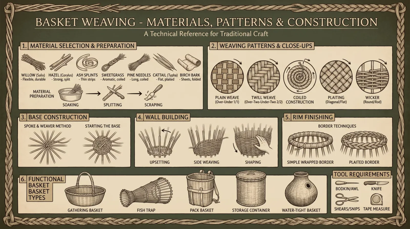
The foundation of durable basketry is the correct choice and preparation of weaving materials. Use flexible, fibrous plants with high tensile strength and resistance to decay.
| Plant Species | Common Use | Harvest Season | Preparation Time | Key Properties |
|---|---|---|---|---|
| Phragmites australis (Common Reed) | Large baskets | Late Summer | 3 days soaking | Long fibers, flexible, lightweight |
| Salix spp. (Willow) | Fine weaving | Early Spring | 5 days soaking | Flexible, strong, pliable |
| Vitis spp. (Wild Grape Vine) | Bindings, handles | Late Autumn | 7 days soaking | Tough, resistant to snapping |
| Yucca filamentosa (Yucca) | Decorative weaving | Mid Summer | 2 days soaking | Fibrous, stiff but pliable |
Step-by-step Material Harvest and Preparation
- Locate and Identify: Use a field guide or test fiber by manual bending; it must flex without snapping.
- Cut Sections: Use a sharp knife or stone blade to cut 1–2 meter lengths near the base.
- Remove Outer Bark: Strip outer bark with a knife or scraping stone to expose inner fibers.
- Soak in Water: Submerge in fresh water for the specified days for each species to increase pliability.
- Dry Partially: Remove from water and dry until leather-like, not brittle.
- Split and Strip: Use a sharp blade to split into strips of 3–5 mm width.
- Store: Keep in a damp cloth or container until use to maintain flexibility.
2. Weaving Patterns and Techniques
Basket strength and utility derive from pattern choice and execution. Select pattern based on intended use.
| Pattern | Description | Structural Benefit | Recommended Uses |
|---|---|---|---|
| Coiling | Spiraling bundle stitched with external binding | High tensile strength, water-resistant | Water baskets, carrying heavy loads |
| Twining | Vertical stakes twisted with horizontal wefts | Flexibility, shape retention | Food storage, open baskets |
| Plaiting | Flat strips woven over and under at right angles | Flat surfaces, rigid structure | Mats, trays, shallow baskets |
| Wicker | Interlaced flexible branches around frame | Lightweight, durable | Large baskets, furniture |
Coiling Basket Construction Protocol
- Form Core Bundle: Gather 10–15 fiber strips, bind tightly with grapevine or yucca strips.
- Start Coil: Coil the bundle into a spiral of 10 cm diameter.
- Stitch Coil: Use thin strips to stitch the coil in place by threading through the bundle’s edge every 2 cm.
- Add Material: Continue coiling, stitching each new coil to the previous.
- Shape Basket: Increase coil diameter gradually for a bowl shape or maintain for cylindrical.
- Finish Rim: Bind the top edge with a thicker strip, folding inward for strength.
- Dry and Harden: Air dry in shade for 72 hours.
Part II: Bow Making
3. Wood Species Selection for Bows

Bow performance depends on wood elasticity, density, and grain straightness. Select seasoned woods known for resilience and strength.
| Wood Species | Density (g/cm³) | Elastic Modulus (GPa) | Best Use | Seasoning Time (Months) | Notes |
|---|---|---|---|---|---|
| Osage Orange | 0.93 | 18 | Longbows | 12 | High strength, rot-resistant |
| Hickory | 0.89 | 16 | General purpose | 9 | Tough, flexible |
| Yew | 0.59 | 14 | Traditional English bows | 18 | High elasticity, prone to cracking if unseasoned |
| Mulberry | 0.65 | 13 | Short bows | 8 | Good flex, less dense |
4. Bow Construction Protocol
Tools Required
| Tool | Purpose | Construction Notes |
|---|---|---|
| Drawknife | Bark removal | Carved from strong hardwood |
| Spokeshave | Shaping and smoothing | Metal blade, wooden handles |
| Bowyer's rasp | Fine shaping | Rough metal file |
| Heat source (fire) | Wood bending | Controlled heat application |
| Measuring tools | Length and draw weight checks | Calibrated sticks or string measures |
Step-by-step Protocol
- Select Bow stave: Straight-grained, knot-free wood, 1.8 m long, 5 cm thick.
- Remove bark: Use drawknife to strip bark evenly.
- Shape limbs: Use spokeshave to taper limbs from handle outward; limbs thinner at tips.
- Tillering: Slowly bend the bow over a tillering tree or form; remove wood from stiff areas using rasp to ensure even bend.
- Heat bend tips: Apply heat carefully to tips to introduce reflex (forward curve) if desired.
- Notch tips: Carve shallow notches at limbs’ ends to hold bowstring.
- Make bowstring: Use twisted sinew, rawhide, or strong plant fibers braided according to Volume X: Stringcraft Codex, Chapter III.
- String bow: Attach bowstring to bottom notch, flex bow to half draw length, loop string in top notch.
- Test draw weight: Use calibrated weights or muscle feel; ideal draw weight depends on intended use (see Table below).
| Intended Use | Draw Weight (lbs) | Draw Length (inches) |
|---|---|---|
| Small game hunting | 30–40 | 20 |
| Medium game hunting | 40–55 | 24 |
| Defense and warfare | 55–70 | 28 |
5. Bow Maintenance and Repair
- Storage: Hang bow unstrung in dry, temperate environment to prevent warping.
- String replacement: Replace every 3 months or after 500 shots.
- Crack repair: Inject hot pine resin mixed with charcoal powder into cracks; clamp with leather strips until hardened.
- Re-tillering: Periodically test limb flexibility and rasp stiff areas.
Part III: Canoe Building
6. Wood Species Selection and Structural Considerations
Canoe wood must combine buoyancy, rot resistance, and workability. Hollowing and carving demand straight-grained wood.
| Wood Species | Density (g/cm³) | Rot Resistance | Buoyancy Index | Typical Use | Seasoning Time (Months) |
|---|---|---|---|---|---|
| Western Red Cedar | 0.32 | High | Exceptional | Dugout canoes | 12 |
| Cottonwood | 0.40 | Moderate | Good | Dugout, frame canoes | 8 |
| Birch | 0.65 | Moderate | Moderate | Frame canoes | 10 |
| Black Ash | 0.54 | Moderate | Moderate | Strip canoes | 10 |
7. Dugout Canoe Carving Protocol
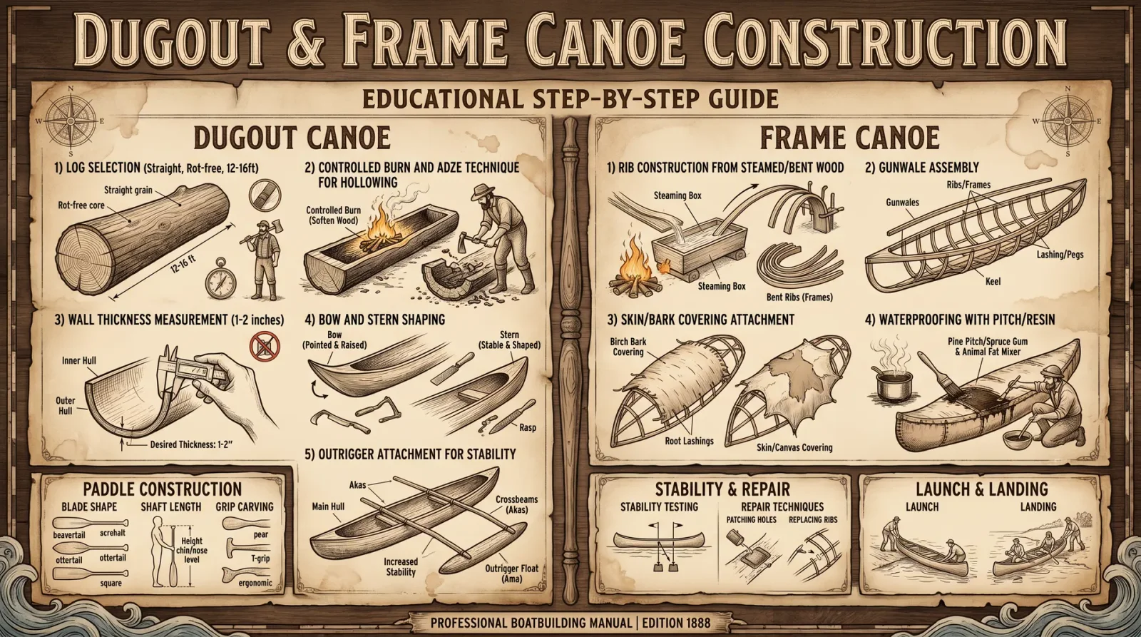
Tools Required
| Tool | Purpose | Construction Notes |
|---|---|---|
| Adze | Primary hollowing | Stone or metal blade, wooden handle |
| Broad axe | Shaping exterior | Heavy, flat blade |
| Chisels | Fine shaping and smoothing | Various sizes, fixed wooden handles |
| Fire source | Softening wood | Controlled low-intensity fire |
| Sanding stones | Surface finishing | Coarse to fine grain |
Step-by-step Protocol
- Select Tree: Straight, 1.5 m diameter, 5–7 m length, live tree with minimal knots.
- Fell Tree: Use traditional wedge and axe method to fell without damaging wood.
- Remove Bark: Strip bark using adze and scraping stones.
- Initial Hollowing: Burn interior lightly using fire, extinguish and scrape charcoal with adze.
- Carve Exterior: Shape hull sides and bottom with broad axe to desired canoe profile.
- Refine Interior: Use chisels and adze to smooth inside; maintain even wall thickness of 3–5 cm.
- Shape Ends: Taper bow and stern for hydrodynamic efficiency.
- Dry Canoe: Air dry slowly in shade for 3 months.
- Waterproofing: Apply natural resins (pine or spruce pitch) heated and mixed with charcoal powder; brush on exterior and interior surfaces.
- Add Seating and Gunwales: Carve or bind wooden strips for structural reinforcement.
8. Frame and Strip Canoe Construction (Advanced)
Detailed protocols and materials for frame and strip canoes are reserved for Volume IX: Advanced Watercraft Codex, Chapter IV.
9. Maintenance and Repair of Canoes
- Storage: Store upside down in shaded, ventilated area to prevent water pooling.
- Crack repair: Clean crack, heat resin mixture (pine pitch and charcoal), apply with wooden spatula, clamp until cooled.
- Hull reinforcement: Bind splits with soaked rawhide strips soaked in resin, allow curing.
- Resin touch-ups: Annually reapply resin coatings for waterproofing.
Summary of Tool and Material Requirements
| Tool / Material | Basket Weaving | Bow Making | Canoe Building |
|---|---|---|---|
| Sharp Knife | Required | Required | Required |
| Drawknife | Optional | Required | Optional |
| Adze | Not used | Not used | Required |
| Spokeshave | Not used | Required | Optional |
| Bowyer's rasp | Not used | Required | Optional |
| Fire source | Optional (drying) | Required (bending) | Required (hollowing) |
| Soaking Container | Required | Not used | Not used |
| Plant fibers | Required | Required (string) | Optional (binding) |
| Resin (pine/spruce) | Optional | Optional | Required (sealing) |
Final Words
Master these protocols without deviation. Your survival depends on the absolute integrity of your crafted tools. The knowledge herein is sacred, passed down through generations to the worthy. Commit every step to memory and practice with discipline. Your life, and those of your kin, may rest upon the flawless execution of these arts.
For purification of plant fibers and advanced string-making techniques, consult Volume VIII: The Water Codex, Chapter II and Volume X: Stringcraft Codex. For advanced watercraft beyond dugout canoes, see Volume IX: Advanced Watercraft Codex.
End of Volume VI
<!-- SECTION 26 -->
Volume VII: Arctic Survival Strategies
The Navigator’s Codex: Complete Navigation, Wilderness Survival, and Earth Skills
Introduction: The Arctic Crucible
In the desolation of polar realms, every elemental force conspires against the unprepared. The Arctic demands mastery of shelter, fire, navigation, and sustenance with precision and rigor. Failure is fatal. This volume imparts the sacred, suppressed knowledge of survival in conditions where the sun may vanish for months, and the cold seeks to unmake flesh and spirit.
You, the chosen apprentice, will learn to erect impervious snow sanctuaries, ignite fire where fuel is scarce and dampness omnipresent, navigate featureless ice expanses, procure nourishment, and preserve your vitality against hypothermia’s deadly advance.
I. Snow Shelter Construction: Fortress of Ice and Snow
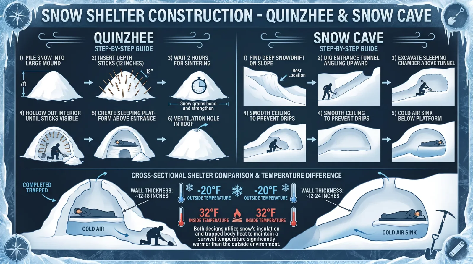
Purpose and Application
Snow shelters serve as thermal sanctuaries against Arctic winds, subzero temperatures, and blinding blizzards. Their insulating properties arise from trapped air within snow’s granular matrix, making snow a formidable barrier against heat loss.
Shelter Types Overview
| Shelter Type | Description | Thermal Efficacy (R-Value) | Use Case | Construction Time (Person-hours) |
|---|---|---|---|---|
| Quinzhee | Hollowed mound of settled snow | 5.0 | Solo or small group, short-term | 2-3 |
| Snow Cave | Excavated chamber in deep snowpack | 8.0 | Extended shelter, severe cold | 3-5 |
| Igloo | Block-built dome from compacted snow | 10.0 | Multiple occupants, longer stay | 4-6 |
Materials Required
- Snow shovel or improvised tool (e.g., sturdy ice axe, wooden plank with nails)
- Snow probe or ski pole for depth measurement
- Knife or saw for block cutting (Igloo only)
- Sturdy trekking poles or branches for framework (optional)
- Insulating bedding materials (see Clothing and Gear section)
Step-by-Step Protocol: Quinzhee Construction (Rapid Insulated Shelter)
- Site Selection Locate a snowfield with minimum 3 feet of dry, powdery snow, free of ice crusts or debris. Avoid avalanche-prone slopes and wind-scoured areas.
- Snow Pile Formation Shovel snow into a mound approximately 8 feet in diameter and 4 feet high. Ensure uniformity to facilitate even settling.
- Settling Period Allow the pile to settle and sinter for 45-60 minutes. To expedite, gently stomp surface to compact and reduce voids.
- Entrance Marking Mark the planned entrance location at the base, oriented away from prevailing wind.
- Excavation Using a shovel or hands, hollow out the interior, leaving walls and ceiling approximately 12 inches thick. Begin excavation from the entrance and expand inward.
- Ventilation Hole Drill a 2-inch diameter ventilation hole at the apex, ensuring airflow and preventing carbon monoxide build-up.
- Entrance Tunnel Dig a low, narrow tunnel entrance to minimize heat loss, extending 3 feet horizontally before rising into the main chamber.
- Insulating Floor Lay branches, skis, or insulating mats on the floor to prevent conductive heat loss to snow.
- Final Inspection Smooth interior surfaces to prevent dripping condensation. Seal gaps with loose snow.
Step-by-Step Protocol: Snow Cave Construction (Advanced)
- Select a snowdrift or snowbank with depth > 6 feet.
- Probe snow depth thoroughly with poles or sticks to avoid hidden air pockets.
- Mark entrance in the leeward side, orient tunnel horizontally before rising.
- Excavate a tunnel 3 feet long, 2 feet wide, and 3 feet high.
- Hollow the main chamber upwards, shaping it dome-like with an internal height of 4-5 feet.
- Create ventilation hole at the apex and seal entrance with snow blocks or backpack.
- Place insulating bedding on floor.
Step-by-Step Protocol: Igloo Construction (Expert)
- Locate snow with adequate hardness for block cutting (wind-packed snow, 6-8 inches thick).
- Cut blocks using a snow saw or sharp knife, each approximately 24 inches long, 12 inches high, and 6 inches thick.
- Lay first ring of blocks in a circle 6 feet diameter, angled slightly inward.
- Successively stack blocks in spiraling inward rings, each layer leaning into the previous, forming a dome.
- Fill gaps with snow to seal wind infiltration.
- Cut entrance tunnel 2 feet high, 1.5 feet wide, with low clearance.
- Create ventilation hole on the dome apex.
II. Fire Starting in Polar Conditions: The Sacred Flame
Challenges
- Wet and frozen fuel sources
- Low oxygen environments inside snow shelters
- Extreme cold affecting ignition materials
Materials Inventory
| Material Type | Description | Preparation |
|---|---|---|
| Tinder | Dry moss, birch bark, fatwood | Shred finely, store in waterproof container |
| Kindling | Small dry twigs <0.25 inch diameter | Collect from under dense evergreen branches |
| Fuel Wood | Larger dry branches and logs | Harvest dead wood, split for dryness |
| Ignition Source | Ferrocerium rod, waterproof matches, magnesium strip | Maintain dry storage |
Step-by-Step Fire Starting Protocol Using Ferrocerium Rod
- Gather tinder, kindling, and fuel wood before fire starting.
- Prepare tinder nest: Arrange finely shredded birch bark or moss into a loose bundle.
- Locate sheltered fire site: Use natural windbreaks or create a snow wall.
- Clear snow down to bare ground or build a platform of dry wood to prevent melting snow extinguishing fire.
- Position tinder nest on platform.
- Scrape ferrocerium rod sharply at 45-degree angle with a steel striker, directing sparks into tinder.
- Blow gently on glowing tinder until flame takes hold.
- Add kindling gradually, increasing size as flame strengthens.
- Add fuel wood once kindling burns steadily.
Fire Starting Protocol Using Magnesium Strip (Alternate Method)
- Scrape magnesium shavings onto tinder nest.
- Strike ferrocerium rod to ignite magnesium powder.
- Blow steadily to nurture flame.
Cold Weather Fire Maintenance
- Keep fire small but consistent to conserve fuel.
- Place stones around fire to radiate heat.
- Use reflective surfaces (foil, emergency blankets) to direct heat.
III. Navigation in Polar Regions: The Frozen Compass
Unique Challenges
- Magnetic compass unreliability near magnetic poles
- Featureless terrain and whiteout conditions
- Rapidly changing ice and snow conditions
Navigation Tools and Techniques
| Tool | Usage | Limitations |
|---|---|---|
| Solar Position | Use sun altitude and azimuth for direction | Requires visible sun |
| GPS Device | Satellite-based positioning | Battery life severely limited by cold |
| Magnetic Compass | Use with caution near poles | Magnetic declination high |
| Natural Landmarks | Ice ridges, rock outcrops | Sparse in vast ice fields |
| Shadow Stick Method | Determine direction via sun shadow | Requires sunlight |
Step-by-Step Protocol: Solar Navigation
- At local solar noon, sun is due south (Northern Hemisphere) or due north (Southern Hemisphere).
- Use a shadow stick: place a vertical stick in the snow.
- Mark the tip of the shadow every 15 minutes.
- Draw a straight line connecting the two shortest shadows; this is the East-West line.
- Perpendicular to this line is North-South axis.
Step-by-Step Protocol: Compass Use Near the Pole
- Consult local magnetic declination charts before expedition.
- Use compass to identify relative directions, adjusting for declination.
- Cross-check compass bearing with solar navigation.
GPS Use Preservation
| Battery Preservation Techniques | Description |
|---|---|
| Keep device close to body heat | Prevent battery drain from cold |
| Use power-saving modes | Activate sleep or low-power |
| Carry extra batteries in insulated pack | Ensure redundancy |
IV. Food Procurement: Sustenance in the Ice
Arctic Flora and Fauna Overview
| Food Source | Identification | Harvesting Technique | Nutritional Value (kcal/100g) |
|---|---|---|---|
| Ice Fishing | Drill hole in ice, use baited line | Drill 3-4 inch diameter hole, lower line slowly | 90-150 (fish dependent) |
| Snow Berries | Crowberry, cloudberry | Collect ripe berries from low bushes | 30-50 |
| Arctic Hare | Trapping with snares | Set snares along known trails | 150-200 |
| Seal (Marine Mammal) | Hunting (advanced, requires tools) | Harpoon or spear hunting | 200-250 |
Step-by-Step Protocol: Ice Fishing
- Identify fishing location using historical knowledge or animal tracks.
- Drill hole through ice, minimum diameter 3 inches using auger or chisel.
- Prepare fishing line with appropriate bait (fish pieces, insects).
- Lower line slowly, avoid disturbing water surface.
- Wait patiently; jig line periodically to attract fish.
- Retrieve fish carefully to avoid line breakage.
- Process and cook immediately or preserve in snow.
Step-by-Step Protocol: Snares for Small Game (Arctic Hare)
- Select narrow game trail or burrow entrance.
- Construct noose using wire or strong cord, loop diameter 4-6 inches.
- Anchor snare securely to a stake or rock.
- Conceal snare with snow or twigs.
- Check traps frequently to prevent decay or loss.
V. Hypothermia Prevention and Treatment: Guarding the Sacred Flame Within
Hypothermia Definition
Core body temperature below 35°C (95°F). Leading cause of death in cold environments.
Prevention Protocol
| Prevention Method | Description | Frequency/Timing |
|---|---|---|
| Layered Clothing | Multiple insulating layers (see Clothing section) | Adjust layers with activity level |
| Hydration | Maintain fluid intake to support circulation | Drink warm fluids every 1-2 hours |
| Nutrition | High-calorie intake to fuel metabolism | Eat small portions every 2-3 hours |
| Shelter | Immediate access to insulated shelter | Enter shelter before fatigue onset |
| Avoid Sweating | Regulate activity to prevent moisture accumulation | Remove layers when sweating begins |
Step-by-Step Protocol: Field Hypothermia Treatment
- Move victim to sheltered area immediately.
- Remove wet clothing carefully.
- Wrap victim in dry insulating materials, including space blankets or snow shelter.
- Apply external heat sources: hot water bottles wrapped in cloth, warm packs (do not apply directly to skin).
- Provide warm, sweetened fluids orally if conscious.
- Encourage gentle movement once shivering subsides.
- Evacuate to medical facility as soon as possible.
VI. Thermal Insulation Values: Materials and Clothing
| Material/Layer | Thermal Resistance (R-Value) per inch | Application | Comments |
|---|---|---|---|
| Down Feather | 3.5 | Insulating jacket, sleeping bags | High loft, compressible |
| Wool | 2.5 | Base layers, hats | Retains warmth even wet |
| Synthetic Fleece | 2.0 | Mid layers | Quick drying |
| Closed-cell Foam Pads | 3.0 | Sleeping pads | Prevents conductive heat loss |
| Snow (packed) | 1.0 | Shelter walls | Provides windproof insulation |
VII. Emergency Signaling Methods in Arctic Environments
| Signal Type | Description | Materials Required | Visibility Range |
|---|---|---|---|
| Mirror Flash | Reflect sunlight with signal mirror | Signal mirror or polished metal | Up to 25 miles |
| Smoke Signal | Create dense black smoke from burning damp wood | Fuel wood, green branches | Up to 5 miles |
| Signal Fire | Large fire with green branches for smoke | Firewood, green branches | Up to 3 miles |
| Ground Symbols | Large geometric shapes (SOS, arrows) in snow | Contrasting materials (rocks, branches) | Visible from aircraft |
| Whistle Blasts | Three short blasts repeated at intervals | Whistle | Audible up to 1 mile |
Step-by-Step Protocol: Signal Mirror Use
- Hold mirror with sighting hole or notch between eye and target.
- Aim reflected sunlight at target (aircraft, distant observer).
- Flash mirror repeatedly in intervals of 2-3 seconds.
- Use clothing or hand to create contrast backgrounds.
Step-by-Step Protocol: Smoke Signal Creation
- Build fire with dry wood base.
- Add green branches or moss to produce dense smoke.
- Maintain fire to sustain smoke for at least 5 minutes every 10 minutes.
VIII. Clothing and Gear Recommendations
Layering System
| Layer Type | Material Recommendations | Function | Notes |
|---|---|---|---|
| Base Layer | Merino wool, silk | Moisture wicking | Avoid cotton |
| Insulation Layer | Down, synthetic fleece | Thermal retention | Adjust thickness to temp |
| Outer Layer | Gore-Tex, windproof shell | Wind and water protection | Breathable |
| Accessories | Wool or synthetic hats, balaclava, mittens | Heat retention, frostbite prevention | Mittens preferred over gloves |
Essential Gear List
| Item | Specification | Purpose |
|---|---|---|
| Insulated boots | Rated to -40°C, waterproof | Foot protection |
| Snow goggles | UV protection, anti-fog | Eye protection |
| Multi-tool | Stainless steel with saw, knife, awl | Versatility in survival tasks |
| Portable stove | Liquid fuel, windproof | Cooking and melting snow |
| Emergency blanket | Reflective Mylar | Heat retention |
| Communication device | Satellite phone or GPS | Emergency signaling |
Final Words
Master these protocols with unwavering discipline. The Arctic does not forgive error, hesitation, or ignorance. Your survival depends on precise execution, reverence for the environment, and unyielding resolve. The knowledge herein is not mere information, but sacred wisdom passed through the ages, now entrusted to you. Guard it, practice it, live it.
For detailed water purification procedures, refer to Volume VIII: The Water Codex, Chapter II. For advanced hunting protocols, consult Volume IX: The Hunter’s Codex. For in-depth cold-weather medical interventions, see Volume XII: The Medic’s Codex.
<!-- SECTION 27 -->
Volume VII: Desert Survival Techniques
Introduction
The desert is a crucible of endurance, a landscape where the margin between life and death is razor-thin. Mastery of desert survival requires a comprehensive command of water sourcing, shelter construction, navigation, and heat management, each a pillar supporting your continued existence. This volume delivers complete, actionable protocols to secure essential resources, defend against environmental extremes, and execute emergency procedures when all else fails.
I. Water Sourcing in Arid Environments
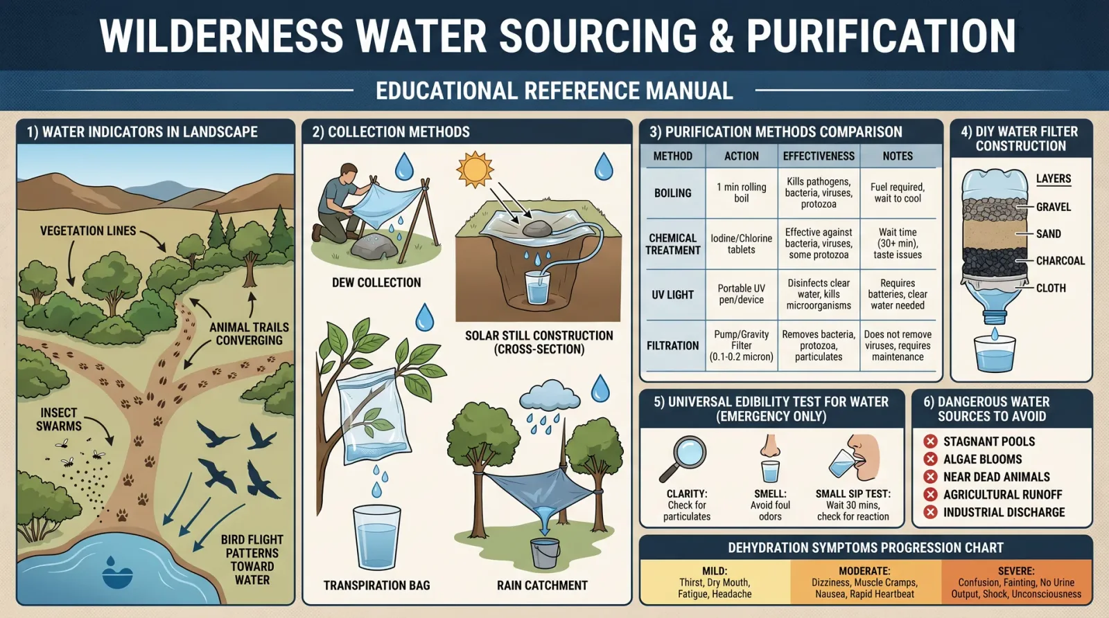
Water is the sine qua non of desert survival. Without it, physiology collapses within days. The desert conceals water in forms subtle and often invisible. This section provides precise methodologies to locate, extract, and conserve water.
A. Identifying Water Sources
- Surface Water:
- Locate dry riverbeds (wadis). After rainfall, water may be present beneath the surface.
- Inspect shaded rock depressions and natural basins for rainwater catchment.
- Observe animal tracks and insect activity converging on water sources.
- Vegetation Indicators:
- Phreatophyte Plants: Deep-rooted species accessing groundwater. Examples include mesquite, willow, and cottonwood.
- Succulents: Store water internally. Cacti are prime examples but require careful extraction (see below).
- Tree and shrub clusters: Dense vegetation often indicates moisture beneath.
- Geological Indicators:
- Rock fractures and porous sandstone may hold subsurface water.
- Salt flats and dry lake beds can indicate previous water presence; sometimes moisture remains below.
- Morning Dew Collection:
- Utilize condensation by placing plastic sheets over vegetation or rock surfaces overnight.
B. Water Extraction Methods
1. Digging for Subsurface Water in Dry Riverbeds
Procedure:
| Step | Action |
|---|---|
| 1 | Identify lowest point in dry riverbed, especially near dense vegetation. |
| 2 | Dig a pit approximately 50 cm deep and 30 cm diameter. |
| 3 | Allow water to seep into the pit; wait 30-60 minutes. |
| 4 | Use cloth or improvised filter to collect water; avoid sediment ingestion. |
| 5 | Repeat adjacent pits if water yield is insufficient. |
2. Cactus Water Extraction
Warning: Only certain cacti are safe; some contain toxic alkaloids.
Procedure:
| Step | Action |
|---|---|
| 1 | Identify barrel cactus or prickly pear (Opuntia spp.) - confirmed safe species. |
| 2 | Using a knife or sharp stone, cut a segment off the cactus pad or barrel section. |
| 3 | Extract the gel-like pulp; avoid colored or yellowish fluids (toxic). |
| 4 | Squeeze pulp into cloth; wring to collect liquid. |
| 5 | Filter liquid before consumption; discard residue. |
3. Solar Still Construction
Materials: Plastic sheet (minimum 1 m²), container, digging tools, cordage.
Procedure:
| Step | Action |
|---|---|
| 1 | Dig a hole approximately 50 cm deep and 70 cm diameter in a sunny location. |
| 2 | Place container at the bottom center of the hole. |
| 3 | Fill hole around container with green vegetation (non-toxic). |
| 4 | Stretch plastic sheet over the hole; secure edges with stones. |
| 5 | Place small stone in center of plastic sheet to create a low point above container. |
| 6 | Condensation will collect and drip into container over several hours. |
| 7 | Collect water every 4-6 hours; repeat process. |
II. Shelter Building for Shade and Thermal Regulation
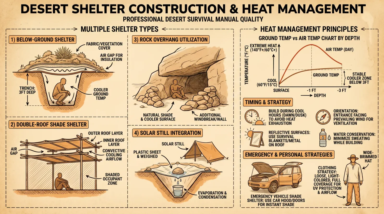
Exposure to solar radiation and temperature extremes is the greatest threat in desert environments. Proper shelter construction mitigates heat stress, conserves moisture, and provides refuge during temperature fluctuations.
A. Selecting Shelter Location
| Criterion | Priority |
|---|---|
| Shade availability | High: Utilize natural shade under rock outcrops or vegetation. |
| Wind protection | Medium: Position shelter on leeward side of terrain features. |
| Proximity to water and food | High: Balance proximity with safety from predators and insects. |
| Ground conditions | Medium: Avoid sandy, loose soil; prefer compact earth to reduce heat conduction. |
B. Types of Desert Shelters
| Shelter Type | Materials Needed | Thermal Properties | Construction Time |
|---|---|---|---|
| Rock Overhang | Natural rock formations | Excellent shade and thermal mass | Immediate |
| Debris Hut | Branches, leaves, brush | Moderate shade, variable insulation | 1-2 hours |
| Reflective Shade | Reflective material (foil, metal), poles | Reflects solar radiation | 30-60 minutes |
| Earth Pit Shelter | Excavated soil, vegetation, plastic sheet | Insulated from heat, cool interior | 2-3 hours |
C. Step-by-Step Guide: Constructing a Debris Hut Shelter
| Step | Action |
|---|---|
| 1 | Locate sturdy branches approximately 1.5-2 m in length. |
| 2 | Construct a frame by leaning branches against a horizontal support pole fixed between two anchor points. |
| 3 | Cover frame with layers of brush, leaves, cactus pads (de-spined), or grass. |
| 4 | Ensure dense coverage to block sunlight and reduce airflow. |
| 5 | Line interior floor with insulating materials (grass, leaves) to avoid direct ground heat. |
| 6 | Create entrance facing away from prevailing wind and sun. |
III. Navigation in the Desert
Accurate navigation prevents becoming lost, conserves energy, and expedites rescue. This section details celestial, terrestrial, and improvised methods.
A. Celestial Navigation Protocol
| Celestial Body | Navigation Use | Steps |
|---|---|---|
| Sun | Determine cardinal directions | 1. Observe sun rise (east) and set (west). |
| North Star (Polaris) | Northern hemisphere fixed point | 1. Locate Big Dipper constellation. |
| 2. Extend "pointer" stars to find Polaris (north). | ||
| Moon | Approximate direction when illuminated | 1. Observe illuminated portion; imaginary line through concave side points to sun. |
B. Shadow Stick Method
Procedure:
| Step | Action |
|---|---|
| 1 | Place a straight stick vertically in the ground. |
| 2 | Mark tip of shadow with a stone or small object (Point A). |
| 3 | Wait 15-30 minutes; mark new shadow tip (Point B). |
| 4 | Draw a straight line between Points A and B; this line approximates east-west axis (A = west, B = east). |
| 5 | Stand with left foot on Point A and right foot on Point B to face north. |
C. Use of Natural Landmarks and Terrain
| Feature | Navigation Use |
|---|---|
| Mountain Ranges | Orient by sun position relative to known landmarks. |
| Dry Riverbeds | Often run downhill; following them may lead to water sources or inhabited areas. |
| Vegetation Zones | Dense clusters often point to water or lower elevation. |
IV. Heat Management and Prevention of Heat-Related Illness
Heat stroke and heat exhaustion constitute immediate mortal dangers. This section provides protocols for prevention, recognition, and emergency treatment.
A. Physiological Limits and Symptoms
| Condition | Core Temperature (°C) | Symptoms | Immediate Action |
|---|---|---|---|
| Heat Exhaustion | 37.5-40 | Weakness, headache, dizziness, nausea, excessive sweating | Move to shade, hydrate, cool body |
| Heat Stroke | >40 | Confusion, loss of consciousness, hot dry skin, rapid pulse | Emergency cooling, emergency evacuation |
B. Preventive Measures
| Measure | Protocol |
|---|---|
| Hydration | Drink small amounts frequently; avoid dehydration (see Volume VIII, Water Codex, Chapter II). |
| Scheduling | Restrict physical activity to early morning or late evening hours. |
| Clothing | Use loose, light-colored garments; cover head and neck with a bandana or cloth. |
| Shade | Construct or rest in shelter during peak sun hours (1100-1600 hours). |
C. Emergency Cooling Protocol
| Step | Action |
|---|---|
| 1 | Move patient to shaded or cooler environment. |
| 2 | Remove excess clothing to facilitate heat loss. |
| 3 | Apply cool water (if available) to skin; fan vigorously to increase evaporation. |
| 4 | Administer water orally if patient is conscious and able to swallow. |
| 5 | Monitor vital signs and prepare for evacuation if symptoms worsen or consciousness is lost. |
V. Desert Flora and Fauna as Sources of Food and Water
Comprehensive tables classify edible and moisture-yielding species; toxic species are excluded.
A. Edible Desert Flora
| Plant Name | Edibility | Preparation | Water Content (%) | Notes |
|---|---|---|---|---|
| Prickly Pear Cactus | Fruit and pads | Remove spines; eat raw or cooked | 85 | High moisture content; pads must be de-spined |
| Mesquite Beans | Seeds | Roast and grind into flour | 10 | High protein content |
| Palo Verde Pods | Seeds | Remove pods, roast seeds | 8 | Requires processing |
| Desert Agave | Heart (core) | Roast underground for 24-48 hours | 60 | High carbohydrate content |
B. Edible Desert Fauna
| Animal | Edibility | Preparation | Water Content (%) | Notes |
|---|---|---|---|---|
| Desert Tortoise | Meat | Cook thoroughly | 60 | Requires permits in some regions |
| Kangaroo Rat | Meat | Small; cook thoroughly | 55 | High protein, small yield |
| Scorpion | Meat | Remove stinger; roast or boil | 40 | Protein source, low fat |
| Locusts | Insects | Remove wings; roast or boil | 60 | High protein |
VI. Signaling and Emergency Evacuation Procedures
In case of distress, signaling and evacuation protocols maximize survival odds and facilitate rescue.
A. Visual Signaling
| Signal Type | Method | Procedure |
|---|---|---|
| Signal Fire | Fires with smoke | 1. Build three fires in a triangle, spaced 10-20 m apart. |
| Ground Signals | Contrasting shapes on ground (SOS, arrows) | 1. Use rocks, branches, or disturbed soil to create signals visible from air. |
| Reflective Signals | Mirror or polished metal | 1. Aim reflected sunlight towards aircraft or distant observers in pulses. |
B. Auditory Signaling
| Signal Type | Method | Procedure |
|---|---|---|
| Whistle Blasts | Series of three short blasts | 1. Repeat every 5 minutes when searching for rescue or alerting nearby parties. |
C. Emergency Evacuation Protocol
| Step | Action |
|---|---|
| 1 | Assess physical condition and injury status; prioritize most vulnerable individuals. |
| 2 | Identify nearest safe destination: water source, habitation, road, or rescue point. |
| 3 | Conserve energy: travel during early morning or late evening to avoid heat exposure. |
| 4 | Mark route with visible indicators (stones, broken branches) to prevent disorientation. |
| 5 | Signal periodically using visual or auditory methods to attract rescue attention. |
| 6 | If unable to proceed, establish a secure shelter and prepare signaling devices. |
Conclusion
Mastery of desert survival demands rigorous application of the protocols herein. Every step, from locating water to signaling for rescue, is a thread woven into the fabric of your survival. The desert yields no mercy; it grants life only to those who command its hidden laws with precision and reverence. Persist in study and practice; your existence depends upon it.
Cross-References:
- For detailed water purification protocols, see Volume VIII: The Water Codex, Chapter II.
- For advanced shelter construction techniques in varied terrains, see Volume V: The Shelter Codex.
- For comprehensive desert flora and fauna toxicology, see Volume IX: The Toxicology Codex.
End of Volume VII: Desert Survival Techniques
<!-- SECTION 28 -->
Volume VII: Jungle Survival Protocols
Section I: Navigation in Tropical Forests
Tropical jungle navigation demands mastery of natural indicators, celestial bodies, and primitive instruments. Reliance solely on modern devices ensures fatal error under canopy cover. This section imparts exact protocols for self-orientation and route maintenance.
Protocol 1: Determining Cardinal Directions Without Instruments
- Sun Positioning Method a. Identify the sun’s location in the sky.
b. At sunrise, the sun rises approximately East; at sunset, approximately West.
c. At solar noon, the sun is directly South in the Northern Hemisphere, and North in the Southern Hemisphere.
d. To refine: Use a stick and shadow method (see step 2).
- Stick and Shadow Method a. Insert a straight stick vertically into bare ground in a sunlit patch.
b. Mark the shadow tip with a small stone (Point A).
c. Wait 15–30 minutes; mark the new shadow tip (Point B).
d. Draw a straight line from Point A to Point B; this line runs approximately West to East, with Point A being West, Point B East.
e. Perpendicular to this line, determine North and South: facing Point B (East), left is North, right is South.
- Moss Growth Caution a. Moss often grows on the North side of trees in temperate zones but is unreliable in humid jungles due to high moisture.
b. Do not depend on moss for direction.
- Natural Indicators a. Observe termite mounds: In many regions, termite mounds have a steeper side facing the sun (South in Northern Hemisphere, North in Southern Hemisphere).
b. Observe ant trails and bird flight patterns at dawn and dusk; birds often move toward water sources.
Protocol 2: Map Creation and Route Marking
- Sketching the Route a. After determining cardinal directions, sketch a route map on bark, large leaves, or soil using charcoal or stones.
b. Mark landmarks such as trees, streams, and clearings, noting estimated distances.
- Trail Marking a. Use broken twigs, stacked stones, or scratched tree bark to mark the path.
b. Avoid creating obvious patterns to prevent attracting hostile attention.
c. Mark only every 50 meters or at critical junctions.
- Dead Reckoning a. Track your estimated distance by counting paces; average step length is approximately 0.75 meters.
b. Use this to estimate distance traveled and to cross-reference with landmarks on your map.
Section II: Shelter Construction in Tropical Forests
Shelter is both a physical barrier and a psychological bastion against jungle elements, predators, and pathogens. Construct shelters to maximize ventilation, waterproofing, and predator deterrence.
Protocol 3: Building a Raised Lean-To Shelter
Materials Needed:
- Long, straight branches (approx. 2.5m length)
- Large leaves (e.g., palm fronds) or bark strips
- Vines or flexible green branches for binding
Step-by-Step Construction:
- Site Selection a. Choose a site elevated from water drainage paths to avoid flooding.
b. Ensure proximity to water but at least 10 meters away to avoid insect swarms.
c. Clear debris, rocks, and sharp objects.
- Support Frame a. Find a sturdy horizontal branch or lean one end of a long branch against a tree at approximately 45°.
b. Place two vertical supports 1.5 meters apart; secure the main ridgepole across them.
- Platform Construction a. Lay multiple straight branches horizontally across the frame, spaced 10-15 cm apart.
b. Secure branches with vines using square knots to prevent slipping.
- Roofing a. Cover the frame with overlapping large leaves or bark strips, starting from the bottom upward to shed water effectively.
b. Tie roofing materials securely with vines to prevent displacement in wind.
- Flooring a. Elevate the sleeping area with a platform of branches to avoid ground moisture and crawling insects.
- Ventilation and Predator Protection a. Leave openings for airflow but cover with fine mesh woven from plant fibers if possible.
b. Surround shelter perimeter with thorny branches or lay a barrier of sharp plant parts to deter snakes and small predators.
Section III: Food Sourcing in the Jungle
Protocol 4: Identification and Harvesting of Edible Plants
Use the following table to identify safe edible plants. Confirm identification visually and through taste tests per the Universal Edibility Test (see Volume IV: Botanical Codex).
| Plant Name | Identification Features | Edible Part(s) | Preparation Notes | Location Commonality |
|---|---|---|---|---|
| Cassava (Manihot esculenta) | Palmately lobed leaves, starchy tuber roots | Roots (after processing) | Must be soaked and cooked to remove toxins | Common near forest edges |
| Breadfruit (Artocarpus altilis) | Large, rough, green fruit with spiked surface | Fruit flesh | Cook before eating | Common in lowland forests |
| Wild Yam (Dioscorea spp.) | Twining vine with tuberous roots | Tubers | Peel and cook thoroughly | Common in shaded understory |
| Taro (Colocasia esculenta) | Large heart-shaped leaves | Corms | Must be boiled to deactivate calcium oxalate crystals | Common near water sources |
| Guava (Psidium guajava) | Small tree, smooth bark, edible fruit | Fruit | Can be eaten raw | Common in clearings |
Protocol 5: Insect Protein Harvesting
| Insect Type | Identification Features | Preparation Method | Nutritional Notes | Collection Sites |
|---|---|---|---|---|
| Termites | White-bodied insects near mounds | Roast or dry over fire | High in protein and fat | Termite mounds and fallen logs |
| Palm Weevil Larvae | Creamy white larvae inside palm trunks | Cook thoroughly before eating | Rich in fat and protein | Dead or dying palm trees |
| Crickets and Grasshoppers | Large hind legs, jumping insects | Roast or dry | High protein, low fat | Open clearings and canopy gaps |
| Ants (Large Species) | Large-bodied ants, often reddish or black | Eat raw or roasted | Rich in formic acid and protein | Near anthills |
Step-by-Step Insect Harvesting:
- Identify target insect species using the above table.
- Locate their habitat: termite mounds, palm trunks, or open ground.
- Extract insects carefully using a stick or hand, avoiding bites or stings.
- Cook insects thoroughly by roasting over coals for a minimum of 10 minutes to kill parasites and pathogens.
- Dry excess protein for storage by hanging in smoke above fire.
Section IV: Disease Prevention and Parasite Avoidance
Protocol 6: Avoiding Predators and Parasites
Predators include snakes, big cats, and aggressive primates; parasites include mosquitoes, leeches, and ticks.
- Predator Avoidance a. Avoid dense underbrush during dawn and dusk when predators hunt.
b. Make noise when moving to alert large animals of your presence.
c. Construct shelter elevated at least 0.5 meters from the ground to avoid snakes.
d. Use thorn barriers or natural repellents (see Volume IX: Toxic Botany for recipes).
- Mosquito and Insect Bite Prevention a. Wear long sleeves and pants made from tightly woven fabric.
b. Apply natural insect repellents: crush fresh citronella or neem leaves and rub on exposed skin.
c. Use smoke from smoldering leaves near shelter to repel insects.
d. Set up a mosquito net if available or weave one from fine plant fibers.
- Leech Avoidance a. Avoid walking through wet, mossy, or swampy areas barefoot.
b. Check skin frequently and remove leeches promptly by sliding a fingernail or flat object under the sucker; do not pull directly to avoid regurgitation of stomach contents.
- Tick Avoidance a. Avoid sitting or lying on grass or foliage.
b. Inspect body and clothing frequently; remove ticks using fine-tipped tweezers.
Protocol 7: Water Purification
For comprehensive water purification protocols, refer to Volume VIII: The Water Codex, Chapter II. Below is a concise, life-saving method:
- Collection a. Source water from flowing streams or rain catchments to minimize contamination.
b. Avoid stagnant water unless no alternatives exist.
- Pre-Filtration a. Filter water through cloth or improvised sand filter to remove particulate matter.
- Boiling a. Bring water to a rolling boil for a minimum of 5 minutes.
b. Allow to cool before consumption.
- Solar Disinfection (SODIS) Alternative a. Fill clear plastic bottles with pre-filtered water.
b. Place bottles in direct sunlight for at least 6 hours.
c. This method uses UV radiation to kill pathogens but is less reliable than boiling.
Section V: Hygiene and First Aid Guidelines
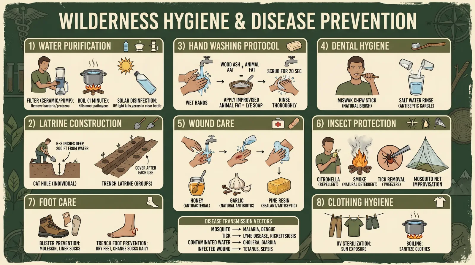
Protocol 8: Personal Hygiene in the Jungle
- Hand Washing a. Wash hands frequently with soap if available, or ash from a wood fire as an abrasive cleanser.
b. Use clean water collected from above protocols.
- Body Cleaning a. Bathe daily in flowing water to remove dirt, sweat, and parasites.
b. Dry thoroughly to avoid fungal infections.
- Clothing Care a. Wash clothes regularly; dry in sunlight to kill microorganisms.
b. Repair tears promptly to maintain protection from insects.
Protocol 9: First Aid for Common Jungle Injuries
| Injury Type | Immediate Actions | Materials Required | Follow-Up Care |
|---|---|---|---|
| Cuts and Lacerations | 1. Clean wound with boiled or purified water. |
- Apply antiseptic from crushed medicinal herbs (see below).
- Cover with clean leaf or cloth bandage. | Boiled water, medicinal herbs (e.g., neem leaves), clean cloth | Change dressing daily, monitor for infection signs (redness, swelling) |
| Snake Bite | 1. Immobilize bitten limb.
- Keep victim calm and still.
- Do not cut or suck the wound.
- Apply a pressure bandage if trained.
- Evacuate to medical facility immediately. | Cloth bandage, splint materials | Monitor vital signs, avoid alcohol or stimulants. |
| Insect Stings/Bites | 1. Remove stinger if present.
- Apply crushed plant poultice with anti-inflammatory properties.
- Monitor for allergic reactions. | Plant poultice (e.g., plantain leaf), clean water | Seek evacuation if anaphylaxis symptoms occur. |
| Fungal Infections | 1. Keep affected area clean and dry.
- Apply antifungal poultices made from crushed garlic or neem. | Garlic, neem leaves | Continue treatment until symptoms resolve. |
Section VI: Tables of Medicinal Herbs for Disease Prevention and Treatment
| Herb Name | Identification Features | Medicinal Properties | Preparation and Use |
|---|---|---|---|
| Neem (Azadirachta indica) | Pinnate leaves, small white flowers | Antibacterial, antifungal, insect repellent | Crush leaves into paste for topical application; boil leaves for antiseptic wash |
| Plantain (Plantago major) | Broad, oval leaves with parallel veins | Anti-inflammatory, wound healing | Crush leaves; apply poultice to wounds and insect bites |
| Garlic (Allium sativum) | Bulb with pungent smell | Antimicrobial, antifungal | Crush cloves; apply paste to fungal infections or bites |
| Turmeric (Curcuma longa) | Orange-yellow rhizome | Anti-inflammatory, antiseptic | Boil in water to make tea; apply paste to wounds |
| Ginger (Zingiber officinale) | Knobby rhizome with strong aroma | Anti-nausea, anti-inflammatory | Brew tea from sliced rhizome; use to alleviate digestive distress |
Summary
This codex section conveys indispensable knowledge for survival in the unforgiving tropical jungle environment. Mastery of navigation, shelter construction, food sourcing, disease prevention, and first aid ensures survival and mission success. All protocols here are distilled from suppressed field reports and classified survival doctrines. The practitioner must execute these instructions with precision and reverence for the jungle’s lethal grandeur.
For related survival disciplines, consult:
- Volume IV: Botanical Codex
- Volume VIII: The Water Codex
- Volume IX: Toxic Botany
End of Volume VII, Jungle Survival Protocols
<!-- SECTION 29 -->
The Complete Practitioner's Codex, Volume VII: Ocean and Coastal Survival
Chapter I: Open Water Navigation Techniques

Mastery of open water navigation is non-negotiable for survival beyond the shore. The ocean is an unforgiving expanse demanding precise, repeatable methods to determine position, course, and progress. This chapter delivers an uncompromising, step-by-step foundation for navigation without modern instruments, and integrating rudimentary tools when available.
Section 1: Celestial Navigation Without Instruments
Step 1: Locating the North Star (Northern Hemisphere)
- Identify the Big Dipper constellation (Ursa Major).
- Trace a line from the two stars forming the outer edge of the Big Dipper's bowl ("pointer stars") upwards about five times the distance between those stars.
- The star at the end of this line is Polaris (North Star).
- Polaris aligns closely with the Earth’s rotational north pole; facing Polaris means facing true north.
Step 2: Determining Latitude by Polaris Elevation
- Using a makeshift quadrant (see Section 2), measure the angle of elevation of Polaris above the horizon.
- This angle in degrees approximately equals your latitude north.
Step 3: Southern Hemisphere Celestial Navigation
- Locate the Southern Cross constellation (Crux).
- Extend the long axis of the cross 4.5 times its length downward toward the horizon to approximate the south celestial pole.
- Align your course by facing this point.
Section 2: Constructing a Basic Quadrant for Angular Measurement
Materials:
- Flat piece of wood/plastic approx. 15cm square
- Protractor or a printed protractor template (if available)
- String approx. 20cm long
- Small weight (e.g., metal washer or stone)
Procedure:
- Attach the string with the weight to the center of the top edge.
- Hold the quadrant vertically, sighting along one edge toward the star.
- Allow the weight to hang freely; the string will indicate the angle on the protractor.
Step 4: Dead Reckoning on Open Water
- Estimate speed by timing the passing of waves or known objects.
- Use a makeshift log line (knotted rope with a float) to measure speed:
- Throw the float overboard attached to a rope with knots every 1.5 meters.
- Count knots passing through your hands in 28 seconds; multiply by 3.6 to get speed in km/h.
- Record direction using the sun’s position or compass if available.
- Calculate distance travelled = speed × time.
Step 5: Using the Sun for Direction
- In the morning, the sun rises roughly in the east; in the evening, it sets roughly in the west.
- At solar noon, the sun is at its highest point, due south in the northern hemisphere and due north in the southern hemisphere.
- Use shadow sticks (gnomons) to estimate solar noon by tracking the shortest shadow length.
Chapter II: Shelter on Rafts or Islands
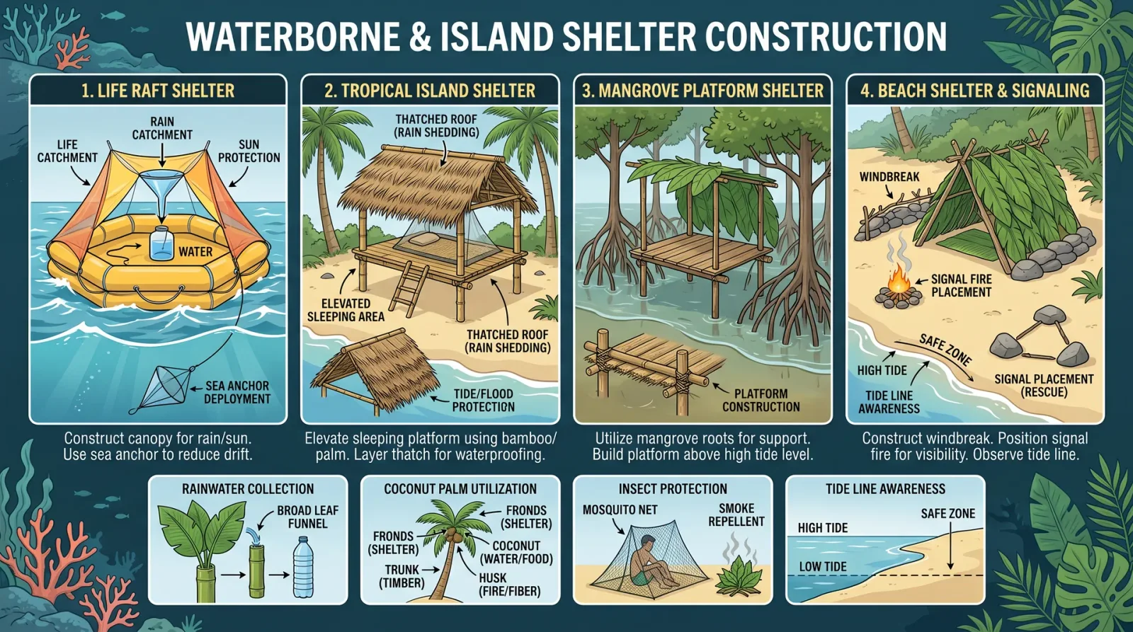
Survival demands secure shelter against elements and wildlife. In oceanic contexts, shelter must be lightweight, water-resistant, and rapidly deployable.
Section 1: Raft Shelter Construction
Materials:
- Driftwood or bamboo (for frame)
- Large leaves (e.g., palm fronds) or tarps/plastic sheeting (if available)
- Natural cordage (vines, stripped bark, or fabricated rope)
Procedure:
- Construct a rectangular frame approx. 2m × 1.5m using driftwood lashed firmly with cordage.
- Build a raised platform by layering smaller sticks and binding securely to keep above water splash and wetness.
- Create a lean-to shelter at one end of the raft:
- Support poles angled at 45 degrees on either side.
- Lash horizontal poles across the top.
- Cover with large leaves or plastic sheeting, overlapping like shingles for rain runoff.
- Secure edges with additional cordage and weighted objects to prevent wind lifting.
Step 2: Island Shelter Construction
- Select a site sheltered from prevailing winds and above the high tide line.
- Clear debris and level ground.
- Build a frame from sturdy branches approximately 2m × 2m.
- Use palm fronds, grasses, or bark to thatch roof and walls, overlapping by at least 20 cm to ensure water runoff.
- Construct a raised bedding platform with sticks or logs to avoid ground moisture and insects.
Chapter III: Fishing in Saltwater Conditions
Fishing is critical for sustenance. This section details improvised gear, indigenous techniques, and maintenance protocols.
Section 1: Building a Basic Fishing Line and Hook
Materials:
- Cordage from vines or stripped bark (length: 5-10m)
- Hook fashioned from bone, shell, wood splinter sharpened and hardened by fire, or safety-pin if available
Procedure:
- Sharpen and harden your hook material by heating and quenching in water.
- Tie the hook securely to the end of the cordage with a strong knot (e.g., improved clinch knot):
- Pass the tag end through the hook eye twice.
- Wrap around the standing line 5-7 times.
- Pass tag end through the first loop and then through the big loop.
- Wet the knot and pull tight.
- Add a sinker (stone or metal weight) 30cm above the hook to keep bait near the bottom.
- Use bait such as small fish, crustaceans, or insects.
Section 2: Net and Trap Construction
Materials:
- Cordage from vines or fibers
- Driftwood for frame
Procedure:
- Create a net by tying knots between strands of cordage spaced 3-5 cm apart.
- Construct a frame for the net to keep it open in the water.
- Deploy near shorelines or tidal pools where fish gather.
- For traps, build funnel openings to allow fish entry but prevent exit.
Chapter IV: Saltwater Purification Protocols
Saltwater consumption causes dehydration and must be avoided. Purification here means extraction of potable water from saltwater or collecting potable water from the environment.
Section 1: Solar Still Construction for Water Extraction
Materials:
- Plastic sheeting or large leaves
- Container for collecting distilled water (bowl, cup)
- Small stone or weight
Procedure:
- Dig a hole approximately 60cm deep and 50cm wide in moist sand or soil near the shore.
- Place container in the center of the hole.
- Cover the hole with the plastic sheet or large leaf, anchoring edges with rocks or sand.
- Place a small stone in the center of the covering, directly over the container, forming an inverted cone.
- Solar heat evaporates moisture, condenses on the underside of the cover, and drips into the container.
- Collect water several times a day.
Section 2: Emergency Desalination by Distillation
Materials:
- Metal or heat-resistant container
- Tubing or improvised condensation surface
- Heat source (sun or fire)
Procedure:
- Fill metal container with saltwater.
- Heat to boiling; evaporated steam rises through tubing or channels to a cooler collection container.
- Condensed steam is freshwater free of salt.
Note: For detailed distillation apparatus construction, see Volume IX: The Water Codex, Chapter IV.
Chapter V: Raft Building Protocol
This section provides an exact, replicable method to build a survival raft capable of supporting up to four survivors and supplies.
Materials and Tools Checklist
| Item | Quantity | Specification |
|---|---|---|
| Driftwood poles | 8 | Diameter 5-10cm, length 2-3m |
| Smaller sticks | 20 | Diameter 2-4cm, length 1-1.5m |
| Cordage | 30 m | Natural fiber or synthetic rope |
| Palm fronds | 10 | Large, fresh |
| Knife/sharp tool | 1 | For shaping and cutting |
Construction Steps
- Select and prepare driftwood: Strip bark and dry poles if possible.
- Form raft base: Arrange 8 driftwood poles parallel, spaced 10 cm apart.
- Secure cross beams: Lay smaller sticks perpendicularly across the base at intervals of 30 cm, lashing tightly.
- Lash all joints: Use square lashings for strength, double knot all ties.
- Build shelter frame: Use three poles to create a triangular support at one end. Lash cross members at 50 cm intervals.
- Weave palm fronds: Attach to shelter frame overlapping for water runoff. Secure with cordage.
- Construct flotation aids: Bind bundles of palm fronds or sealed empty containers under raft for buoyancy increase.
- Test raft: Before launch, apply pressure by standing and adding weight to check stability.
Chapter VI: Signaling and Emergency Rescue Protocols
Effective signaling can mean the difference between rescue and oblivion.
Section 1: Visual Signaling
| Signal Type | Materials Needed | Procedure | Purpose |
|---|---|---|---|
| Mirror Flashing | Polished mirror | Angle mirror toward sun, reflect flash toward rescuers or aircraft | Attract distant attention |
| Signal Fire | Dry wood, leaves | Build small fire with green leaves for smoke during day; add dry wood for flame at night | Attract attention |
| Flag or Cloth | Bright colored cloth | Wave or raise on pole | Visual distress signal |
| SOS Symbols | Rocks, logs | Arrange "SOS" in large letters on sand or open area | Universal distress symbol |
Step-by-Step: Constructing a Signal Fire
- Gather dry wood and green leaves (for smoke).
- Build a teepee-shaped pile with larger wood outside and green leaves inside.
- Place tinder at base and ignite.
- Add fuel to maintain fire and smoke visibility.
Section 2: Acoustic Signaling
- Use metal objects to strike wood or metal surfaces to create loud, rhythmic sounds.
- Three short blasts or knocks universally indicate distress.
Chapter VII: Ocean Currents, Weather Patterns, and Edible Marine Species
Table 1: Major Ocean Currents Affecting Survival Navigation
| Current Name | Location | Direction | Speed (km/h) | Notes |
|---|---|---|---|---|
| Gulf Stream | North Atlantic | Northeast | 3-5 | Warm current, aids northbound |
| California Current | Eastern Pacific | Southward | 0.5-1 | Cold current, affects west coast |
| Kuroshio Current | Western Pacific | Northward | 1-2 | Warm current, typhoon influence |
| Benguela Current | Southwest Africa | Northward | 0.5-1 | Cold current, nutrient rich |
| Antarctic Circumpolar | Southern Ocean | Eastward | 0.8-1.5 | Cold, powerful circumpolar flow |
Table 2: Common Coastal Weather Patterns and Indicators
| Pattern | Signs | Survival Impact | Response |
|---|---|---|---|
| Trade Winds | Steady winds from east | Stable weather, aids navigation | Use for course setting |
| Tropical Cyclone | Sudden pressure drop, clouds | Extreme danger, seek shelter | Prepare for storm survival |
| Sea Breeze | Afternoon onshore wind | Cooling effect, stable | Use to estimate time of day |
| Fog | Reduced visibility | Navigation hazard | Use sound and close-range navigation |
Table 3: Edible Marine Species and Basic Preparation Notes
| Species | Identification Features | Edible Parts | Preparation Notes |
|---|---|---|---|
| Parrotfish | Bright colors, beak-like teeth | Flesh | Remove scales, cook thoroughly |
| Seaweed (various) | Leafy, green/brown | Leaves | Rinse to remove sand, eat raw or cooked |
| Crabs | Hard shell, claws | Meat of claws and body | Boil or roast to avoid toxins |
| Mussels | Blue-black shells | Flesh inside | Cook thoroughly, discard open shells |
| Octopus | Soft body, tentacles | Flesh | Cook thoroughly to prevent toxins |
Chapter VIII: Survival Kit Recommendations for Ocean and Coastal Environments
| Item | Quantity | Purpose | Notes |
|---|---|---|---|
| Multipurpose knife | 1 | Cutting, carving, defense | High-quality stainless steel |
| Cordage (natural/synthetic) | 30 m | Lashing, fishing, shelter | Prefer nylon or strong fibers |
| Metal container | 1 | Water collection and boiling | Lightweight, corrosion-resistant |
| Mirror (signal) | 1 | Visual signaling | Polished metal or glass |
| Fishing hooks and line | Set | Fishing | Pre-made or improvised |
| Fire starter (flint/steel) | 1 | Fire ignition | Waterproof tinder recommended |
| Plastic sheeting/tarp | 1 | Shelter, water collection | Minimum 2m × 2m |
| Small first aid kit | 1 | Wound care, minor injuries | Include antiseptic, bandages |
| Compass | 1 (optional) | Directional navigation | If available |
This volume, Volume VII: Ocean and Coastal Survival, is a sacred transmission of life-preserving knowledge. Every step, every method, and every protocol is crafted for immediate application under the harshest conditions. The ocean demands respect and precision; survival hinges on your unwavering adherence to these instructions. For advanced water purification methods, see Volume VIII: The Water Codex, Chapter II. For advanced celestial navigation devices, refer to Volume X: The Astral Codex, Chapter V.
May this codex serve you with the gravity and clarity it embodies.
<!-- SECTION 30 -->
The Complete Practitioner's Codex, Volume VII: Mountain Survival and Altitude Adaptation
Preface
This volume delivers the arcane, life-preserving knowledge required for navigation and survival in the harsh, unforgiving environments of high-altitude mountains. The thin air above the timberline is merciless to the unprepared. Herein are the exact protocols for altitude sickness prevention, shelter construction optimized for cold and wind, weather prediction through natural signs, and rescue signaling methods. You will also find exhaustive tables cataloging the flora and fauna of mountainous regions, detailed hypoxia symptomatology, and acclimatization schedules that allow your body to endure the rarefied atmosphere.
This knowledge is sacred, life-or-death. Follow each step without deviation. Mastery of this volume is mastery of survival itself.
Chapter I: Navigating High-Altitude Terrain
1. Terrain Analysis and Route Planning
High-altitude terrain is treacherous, with hidden crevasses, avalanche zones, and unstable scree. Before proceeding:
- Obtain topographic maps of the region, ideally with contour intervals of 20 meters or less.
- Use a clinometer to measure slope angles (see Section 3 for construction).
- Identify avalanche-prone slopes: slopes between 30° and 45° with significant snow accumulation are highest risk.
- Mark water sources, shelters, and known hazards.
- Plan routes along ridgelines or valley floors to avoid unstable slopes.
2. Construction of a Field Clinometer
A clinometer is essential for slope measurement and avalanche risk assessment.
Materials:
| Material | Quantity | Specifications |
|---|---|---|
| Protractor (plastic or metal) | 1 | 180° scale, marked in degrees |
| Small weight (washer or nut) | 1 | Approximately 10 grams |
| String (cotton or nylon) | 15 cm | Thin, non-stretch fiber |
| Rigid backing (cardboard or thin wood) | 1 | 10 cm x 10 cm |
| Adhesive (super glue or tape) | As needed |
Assembly Steps:
- Attach the protractor flat onto the rigid backing.
- Tie the string to the center pivot point of the protractor’s flat edge.
- Attach the weight to the loose end of the string.
- Ensure the string hangs freely over the degree scale when the device is held vertically.
Usage:
- Hold the clinometer so that the flat edge aligns with the slope.
- Read the angle indicated by the string’s position on the protractor scale.
Chapter II: Altitude Sickness Prevention and Acclimatization

Altitude sickness results from hypoxia due to decreased atmospheric pressure at elevation. The following protocols prevent onset and mitigate symptoms.
1. Hypoxia Symptomatology Table
| Symptom | Severity Level | Description |
|---|---|---|
| Headache | Mild | Persistent, dull pain, usually frontal |
| Nausea and Vomiting | Mild to Moderate | Loss of appetite, occasional vomiting |
| Dizziness | Moderate | Lightheadedness, balance impairment |
| Fatigue | Mild to Moderate | Reduced physical and mental stamina |
| Tachypnea (rapid breathing) | Moderate | Increased respiratory rate |
| Peripheral Edema | Moderate | Swelling in hands/feet |
| Confusion and Disorientation | Severe | Cognitive impairment, memory loss |
| Ataxia (lack of coordination) | Severe | Poor motor control, stumbling |
| Cyanosis (blue lips/fingertips) | Severe | Oxygen deprivation manifesting visibly |
| Pulmonary Edema (fluid in lungs) | Critical | Severe breathlessness, coughing up frothy sputum |
| Cerebral Edema (brain swelling) | Critical | Severe headache, coma, death if untreated |
2. Acclimatization Schedule
Adherence to acclimatization is non-negotiable. Ascend no faster than the rates specified below:
| Altitude Range (meters) | Maximum Daily Gain (meters) | Rest Days Required |
|---|---|---|
| 0 – 3,000 | 500 | None |
| 3,000 – 4,000 | 300 | 1 rest day every 600 meters |
| 4,000 – 5,500 | 200 | 2 rest days every 600 meters |
| Above 5,500 | 100 | 3 rest days every 600 meters |
3. Step-by-Step Acclimatization Protocol
- Ascend according to the schedule in the table above.
- At every 600 meters gained above 3,000 meters, schedule rest days with no further ascent.
- Hydrate intensively during rest days, minimum 4 liters per day.
- Avoid alcohol and depressants.
- Perform light exercise (walking) during rest days to stimulate breathing adaptation.
- Monitor for symptoms; if symptoms progress beyond mild headache or nausea, stop ascent and descend immediately.
- Use supplemental oxygen only as emergency intervention; it impedes acclimatization if used continuously.
Chapter III: Shelter Construction at High Altitude
Shelter must resist extreme cold, high winds, and snow accumulation.
1. Site Selection
- Choose a location with natural windbreaks: behind rock outcrops or dense vegetation.
- Avoid avalanche zones, riverbeds (risk of flooding), and depressions where cold air pools.
- Select a flat area to facilitate construction and prevent water pooling.
2. Snow Cave Shelter Construction
Snow caves provide excellent insulation.
Materials: Snow (deep, compacted), shovel or digging tool (improvised if needed).
Construction Steps:
- Identify a snowdrift with a depth of at least 1.5 meters.
- Mark a circular floor with a diameter of 1.5 meters.
- Dig vertically downwards, then horizontally inward to create a dome-shaped cavity.
- Ensure the ceiling is domed to prevent collapse.
- Carve a small ventilation hole (5 cm diameter) at the apex.
- Create a low entrance tunnel to reduce heat loss.
- Smooth interior walls to prevent dripping.
- Place insulating floor mats or pine boughs on the floor if available.
Thermal Properties:
Snow cave interiors stabilize near 0°C, significantly warmer than outside temperatures.
3. Rock and Branch Wind Shelter
Use when snow is insufficient.
Materials: Large rocks, branches, tarps, or emergency blankets.
Construction Steps:
- Arrange rocks to build a U-shaped wall facing the prevailing wind.
- Weave branches horizontally between rocks to fill gaps.
- Cover the structure with tarps or emergency blankets, securing with rocks or stakes.
- Insulate the floor with branches or blankets.
- Construct a low entrance facing away from the wind.
Chapter IV: Weather Prediction Protocols in Mountain Environments
Mountain weather changes rapidly. Accurate prediction is critical.
1. Observation Protocols
| Indicator | Interpretation | Action Required |
|---|---|---|
| Increasing cumulus clouds | Developing thunderstorms | Seek shelter immediately |
| Red sky at sunset | High pressure, fair weather | Prepare for clear conditions |
| Red sky in morning | Incoming low pressure, storms likely | Delay travel, reinforce shelter |
| Sudden drop in temperature | Cold front approaching | Add clothing, secure shelter |
| Increasing wind speed | Approaching storm | Cease travel, seek shelter |
| Halo around the sun or moon | High moisture content, rain/snow imminent | Prepare for precipitation |
2. Cloud Reading and Altitude Correlation
Use the following chart to interpret cloud types and altitude relevance:
| Cloud Type | Altitude Range (meters) | Weather Implication |
|---|---|---|
| Cirrus | 6,000 – 13,000 | Approaching warm front, fair weather |
| Cumulus | 500 – 3,000 | Local convection, possible showers |
| Stratus | 0 – 2,000 | Overcast, stable weather |
| Nimbostratus | 0 – 3,000 | Continuous rain or snow |
| Cumulonimbus | 500 – 12,000 | Thunderstorms, severe weather |
Chapter V: Mountain Flora and Fauna Reference Tables
1. Edible and Medicinal Mountain Flora
| Species Name | Altitude Range (m) | Edible Parts | Medicinal Use | Preparation Notes |
|---|---|---|---|---|
| Alpine Willowherb (Epilobium) | 1,500 – 3,500 | Leaves, young shoots | Anti-inflammatory | Boil leaves for tea; young shoots raw |
| Edelweiss (Leontopodium) | 1,800 – 3,000 | Flowers | Antioxidant, wound healing | Infuse flowers in hot water |
| Mountain Sorrel (Oxyria digyna) | 500 – 3,000 | Leaves | Vitamin C source | Consume raw or cooked |
| Rhodiola Rosea | 1,200 – 3,500 | Root | Adaptogen, altitude sickness support | Dry and powder root; take 250mg daily |
| Wild Garlic (Allium ursinum) | 500 – 1,500 | Leaves, bulbs | Antibacterial, cardiovascular health | Use fresh leaves in cooking |
2. Dangerous Mountain Flora
| Species Name | Identifying Features | Toxic Components | Symptoms of Poisoning |
|---|---|---|---|
| Monkshood (Aconitum) | Purple helmet-shaped flowers | Alkaloids (aconitine) | Nausea, paralysis, cardiac arrest |
| Foxglove (Digitalis) | Bell-shaped purple flowers | Cardiac glycosides | Heart arrhythmias, dizziness |
| Death Camas (Zigadenus) | Grass-like leaves, white flowers | Steroid alkaloids | Vomiting, seizures, cardiac failure |
3. Mountain Fauna and Potential Threats
| Species | Habitat Altitude (m) | Behavior | Danger Level | Notes |
|---|---|---|---|---|
| Mountain Goat | 1,500 – 4,000 | Generally non-aggressive | Low | Avoid startling; aggressive during rut |
| Snow Leopard | 3,000 – 5,500 | Solitary, nocturnal predator | High | Avoid at all costs; use noise to deter |
| Marmot | 1,500 – 3,000 | Burrowing rodent | Low | Avoid burrow entrances |
| Viper (Vipera berus) | 500 – 2,500 | Venomous snake | High | Step carefully; treat bites as medical emergency |
Chapter VI: Rescue Signaling Methods in Mountain Environments
Survival depends on effective signaling for rescue.
1. Visual Signaling
| Method | Materials Needed | Instructions | Visibility Range |
|---|---|---|---|
| Ground Signal Panels | Rocks, branches, clothing | Arrange in ‘SOS’ or large geometric shapes | Up to 10 km by air |
| Signal Mirror | Reflective surface (mirror, CD) | Reflect sunlight toward aircraft or distant observers | Up to 20 km |
| Smoke Signal | Green vegetation, fire source | Build a smoky fire creating dense smoke bursts | Up to 15 km |
| Flashlight or Torch | Battery-powered light source | Flash Morse code signals (SOS: ...---...) | Up to 5 km in darkness |
2. Audible Signaling
| Method | Equipment Needed | Instructions | Range (meters) |
|---|---|---|---|
| Whistle | Metal whistle | Three short blasts repeated every minute | 400 – 600 |
| Shouting | None | Yell loudly in three bursts | 200 – 300 |
| Rock or Metal Impact | Hard rock, metal object | Strike to create rhythmic noise (three strikes) | 500 |
3. Universal Rescue Signal Protocol
- Use three signals (visual or audible) repeated in a pattern.
- If using fire, create daytime smoke signals with green vegetation and nighttime firelight signals.
- Always attempt signals during daylight hours when visibility is highest.
- Use signal mirrors when the sun is visible; angle toward aircraft or distant observers.
- Establish a signal station at the highest safe point in the vicinity.
Appendix: Critical Dosage for Altitude Sickness Pharmacotherapy
While natural acclimatization is paramount, the following pharmacological agents serve as last-resort aids.
| Medication | Dosage | Administration Frequency | Notes |
|---|---|---|---|
| Acetazolamide | 125 mg twice daily | Every 12 hours | Start 24 hours before ascent |
| Dexamethasone | 4 mg every 6 hours | As needed | For severe cerebral edema symptoms |
| Nifedipine | 20 mg slow release | Every 8-12 hours | For high altitude pulmonary edema |
| Supplemental Oxygen | 2-4 L/min via mask | Continuous as necessary | Emergency use only; do not rely on |
Conclusion
Master these protocols with discipline and precision. The mountain’s austerity demands respect and preparation. Your life, your mission, and the legacy of the Practitioner depend upon it.
For cross-referenced water and food purification protocols, see Volume VIII: The Water Codex, Chapter II.
This concludes Volume VII: Mountain Survival and Altitude Adaptation. Proceed with vigilance.
<!-- SECTION 31 -->
The Complete Practitioner's Codex, Volume VII: Urban Collapse Survival Strategies
Chapter I: Urban Navigation in Post-Collapse Environments

Urban landscapes, once structured and predictable, become chaotic labyrinths after societal collapse. Navigating these transformed environments demands mastery of spatial awareness, environmental cues, and improvised tools. This chapter imparts precise, actionable protocols to traverse collapsed urban zones with maximum safety and efficiency.
Section 1.1: Fundamental Urban Navigation Principles
- Map Acquisition and Creation
- Step 1: Obtain any available city maps from public libraries, transit stations, or personal devices.
- Step 2: If maps are unavailable or outdated, construct a mental map by identifying permanent landmarks: large buildings, bridges, rivers, and road grids.
- Step 3: Use chalk or charcoal to mark critical points on walls near safe shelters for orientation and route memory.
- Landmark Identification and Usage
- Step 1: Identify at least three fixed landmarks from any vantage point.
- Step 2: Orient yourself by visualizing a triangle formed by these landmarks.
- Step 3: Use the triangle method to triangulate your position relative to your destination.
- Improvised Compass Construction
- Materials: Needle or small metal pin, leaf or small piece of cork, container of still water.
- Step 1: Magnetize the needle by rubbing it on silk or hair 50 times in one direction.
- Step 2: Affix the needle horizontally on the leaf or cork.
- Step 3: Float the assembly on water in the container; the needle will align north-south.
- Step 4: Confirm orientation using sun position (sun rises east, sets west).
- Route Selection Protocol
- Avoid wide-open streets during daylight; use alleyways or building interiors.
- Plan routes that offer multiple exits and cover.
- Prioritize routes passing by known resource caches (see Section 3.2).
Section 1.2: Hazard Awareness and Avoidance
| Hazard Type | Description | Indicators | Avoidance Strategy |
|---|---|---|---|
| Structural Collapse | Unstable buildings and debris | Cracks, leaning walls, creaking | Circumvent buildings with visible damage; test floors with poles before entry |
| Contaminated Zones | Chemical spills, biological waste | Discoloration, foul odor | Use respirators (see Volume X: Protective Gear, Chapter III); avoid area entirely |
| Hostile Occupants | Armed individuals or gangs | Graffiti warnings, barricades | Move silently; avoid eye contact; use alternate routes |
| Electrical Hazards | Exposed live wires, damaged transformers | Sparking, buzzing sounds | Never touch; maintain minimum 5-meter distance |
| Traps and Alarms | Improvised security devices | Tripwires, booby traps, noise | Scan ground carefully; use long tools to probe ahead |
Chapter II: Shelter Selection and Fortification

Shelter choice in urban collapse is paramount for survival. It must balance concealment, structural integrity, resource proximity, and defensibility. Follow these prescriptive protocols for identifying, securing, and reinforcing safe havens.
Section 2.1: Safe Shelter Selection Criteria
| Criterion | Parameters | Assessment Method | Priority Level |
|---|---|---|---|
| Structural Integrity | Minimal damage, solid foundations | Visual inspection, sound test (tap walls) | High |
| Concealment | Camouflage potential, hidden access | Visibility from main roads | High |
| Resource Proximity | Access to water, food caches, medical supplies | Distance under 500 meters | Medium |
| Defensibility | Single point of entry, clear lines of sight | Count entry points and sight lines | High |
| Environmental Safety | Absence of chemical, biological hazards | Smell test, visual cues | High |
Section 2.2: Shelter Fortification Protocol
- Perimeter Reinforcement
- Step 1: Barricade all entry points using scavenged wood, metal panels, or furniture.
- Step 2: Secure barricades with nails, screws, or twisted wire.
- Step 3: Create tripwire alarms at secondary entry points using fishing line and empty cans.
- Visibility Reduction
- Step 1: Cover windows with dark fabric or debris to prevent light escape.
- Step 2: Use natural camouflage—ivy, branches, or dust—to blend exterior walls.
- Ventilation Management
- Step 1: Assess ventilation points for easy access by intruders.
- Step 2: Install grates or mesh screens fabricated from metal scraps.
- Step 3: Ensure airflow is maintained to prevent suffocation.
- Escape Route Preparation
- Step 1: Identify at least two alternative exits.
- Step 2: Keep escape routes clear and marked internally with chalk arrows.
- Step 3: Store essential supplies near escape exits for rapid evacuation.
Chapter III: Scavenging Protocols and Resource Management
Urban scavenging is a critical survival skill. It requires stealth, efficiency, and knowledge of common resource locations. This section details exact methods for locating, retrieving, and conserving urban resources.
Section 3.1: Scavenging Safety Protocol
- Pre-Scavenge Preparation
- Step 1: Equip light body armor from salvaged materials (e.g., layered leather, scrap metal).
- Step 2: Carry a reliable weapon (see Volume V: Improvised Weaponry, Chapter II).
- Step 3: Assemble essential tools: crowbar, flashlight with fresh batteries, sturdy gloves.
- Scavenge Team Formation
- Step 1: Operate in groups of 2-4; designate roles: scout, carrier, rear guard.
- Step 2: Establish hand signals for silent communication.
- Step 3: Set extraction time limits based on daylight and threat levels.
- Entry and Exit Procedure
- Step 1: Approach target location from least visible direction.
- Step 2: Conduct a silent perimeter sweep.
- Step 3: Enter quietly; avoid touching unstable debris.
- Step 4: Collect prioritized items (see Section 3.3).
- Step 5: Exit via pre-planned route; maintain stealth.
Section 3.2: Urban Resource Cache Locations
| Location Type | Typical Resources Found | Risk Level | Notes |
|---|---|---|---|
| Supermarkets | Non-perishable food, canned goods | Medium | Likely looted; check back storage areas |
| Pharmacies | Medical supplies, disinfectants | High | May contain hazardous chemicals; handle with care |
| Schools | Water containers, clothing, tools | Medium | Often unsecured, good for varied supplies |
| Industrial Sites | Fuel, scrap metal, tools | High | High risk due to hazardous materials and security |
| Residential Basements | Food stores, batteries | Low | Quiet areas but structurally unstable |
Section 3.3: Priority Scavenging Item List
| Item Category | Specific Items | Use Case |
|---|---|---|
| Food | Canned vegetables, protein bars, dried grains | Nutrition, sustained energy |
| Water | Bottled water, purification tablets | Hydration, contamination control |
| Medical Supplies | Bandages, antiseptics, painkillers | Injury treatment |
| Tools | Multipurpose knives, screwdrivers, crowbars | Shelter building, defense |
| Communication | Batteries, radios, signal mirrors | Maintaining contact, signaling |
Chapter IV: Community Defense and Security Protocols
Post-collapse urban zones attract hostile elements. Defense requires systematic planning, resource allocation, and disciplined execution.
Section 4.1: Perimeter Defense Setup
- Establish Defensive Lines
- Step 1: Identify natural choke points within community perimeter.
- Step 2: Construct barricades using scavenged materials (see Chapter II, Section 2.2).
- Step 3: Position sentries at elevated vantage points with clear fields of fire.
- Tripwire and Alarm Systems
- Step 1: Install tripwires on all access paths using wire or fishing line.
- Step 2: Attach noise-making devices (cans, bells) to tripwires.
- Step 3: Conduct daily maintenance checks.
- Rotational Guard Scheduling
- Step 1: Create a guard roster with 2-hour shifts.
- Step 2: Ensure guards are equipped with weapons and communication devices.
- Step 3: Implement stealth patrols during night hours.
Section 4.2: Defensive Engagement Protocol
| Stage | Action | Purpose |
|---|---|---|
| Detection | Silent observation, alarm activation | Identify threat early |
| Warning | Loud verbal warnings, flare signals | Deter intruders |
| Engagement | Use non-lethal force where possible | Minimize escalation |
| Lethal Force | Use firearms or improvised weapons only as last resort | Protect community lives |
| Retreat | Controlled fallback to secondary defense | Preserve forces and regroup |
Section 4.3: Community Communication and Signaling Methods
- Visual Signaling
- Materials: Mirrors, colored cloth, flashlight.
- Step 1: Use mirror flashes to send Morse code over distances up to 2 km.
- Step 2: Hang colored cloth strips at predetermined locations to convey messages (e.g., red for danger, white for safe).
- Auditory Signaling
- Step 1: Use whistle blasts or bell rings in coded sequences.
- Step 2: Limit signals to agreed codes to avoid enemy confusion.
- Written Codes
- Step 1: Use chalk or charcoal to mark symbols on walls.
- Step 2: Develop and disseminate a symbol codebook within the community.
Chapter V: Urban Escape Route Planning and Execution
Escape routes are lifesaving contingencies. Establish, maintain, and rehearse them rigorously.
Section 5.1: Escape Route Mapping
| Route Number | Start Point | Primary Path | Secondary Path | Distance (meters) | Hazards Identified |
|---|---|---|---|---|---|
| Route 1 | Community Shelter | Alley 12 → Sewer Exit | Rooftop → Backstreet | 850 | Structural collapse, hostiles |
| Route 2 | Medical Station | Subway Tunnel | Underground Parking | 1200 | Flooding, electrical hazards |
| Route 3 | Food Cache Site | Abandoned Shop → Park | Sidewalk → Riverbank | 600 | Tripwire traps, hostile patrols |
Section 5.2: Escape Route Preparation Protocol
- Route Clearing
- Step 1: Remove debris and potential traps.
- Step 2: Mark route discreetly with chalk arrows.
- Step 3: Identify and note quick cover points.
- Rehearsal
- Step 1: Conduct regular practice runs with community members.
- Step 2: Alternate routes to avoid predictability.
- Emergency Supplies Stashing
- Step 1: Store compact survival kits at route entry points.
- Step 2: Kits include water, food rations, first aid, and signaling devices.
Appendix A: Comprehensive Table of Common Urban Hazards
| Hazard | Description | Detection Method | Immediate Action |
|---|---|---|---|
| Gas Leaks | Leaking natural gas or propane | Smell of sulfur, hissing sound | Evacuate area; avoid sparks |
| Electrical Fires | Fires from exposed wiring | Visible sparks, smoke | Use fire extinguisher; avoid water |
| Structural Collapse | Falling debris or unstable buildings | Cracks, sounds of shifting | Evacuate; avoid proximity |
| Chemical Spills | Toxic substances from industrial sites | Discoloration, strong odors | Wear respirators; seal off area |
| Hostile Individuals | Armed gangs, desperate survivors | Presence of weapons, barricades | Avoid confrontation; alert sentries |
Appendix B: Standard Urban Survival Signaling Codes
| Signal Type | Code Description | Meaning | Recommended Use |
|---|---|---|---|
| Mirror Flash | Three quick flashes | Need immediate assistance | Long-distance signaling |
| Cloth Color | Red strip | Danger, hostile presence | Visible from a distance |
| Whistle Blasts | Two short blasts | All clear | Communicate safe status |
| Chalk Mark | Circle with dot inside | Safe to enter | Marking shelters |
| Chalk Mark | X mark | Avoid area | Marking hazards |
This volume imparts the unvarnished truths and protocols essential for survival in collapsed urban environments. Mastery of these instructions ensures not only individual survival but the preservation and protection of the community. Adhere strictly to every step, for the urban wilderness is merciless and unforgiving.
<!-- SECTION 32 -->
Volume VII: Nuclear, Chemical, and Biological Survival
Chapter I: Protective Measures, Decontamination, and Symptom Management for NBC Events

This volume serves as the definitive manual for survival in the most hostile environments created by nuclear, chemical, and biological (NBC) threats. The following protocols are the culmination of classified research, field-tested procedures, and suppressed methodologies. Mastery of these instructions is non-negotiable for survival and mission success.
Section 1: Protective Measures
1.1 Shelter Sealing Protocol
The first line of defense against NBC contamination is the establishment of a properly sealed shelter. This shelter must be impervious to particulate, vapor, and aerosol intrusion.
Materials Needed:
| Item | Description | Minimum Quantity |
|---|---|---|
| Heavy-duty polyethylene sheeting | 6 mil thickness or greater, 10 ft x 25 ft sheets | Sufficient to cover all openings |
| Butyl rubber tape | Waterproof, 3-inch width | 100 ft |
| Industrial-grade spray adhesive | Chemical resistant | 1 can |
| Duct tape | High adhesion | 200 ft |
| Plastic zipper seals | For door entry points | 1 per entry |
| Sealant putty | Non-drying, moldable | 2 lbs |
Step-by-step Shelter Sealing Procedure:
- Select Shelter Location: Choose an underground or interior room with minimal external walls. Avoid windows and ventilation shafts if possible.
- Clear Entry Points: Remove all loose materials, dust, and debris from door frames, windows, vents, and cracks.
- Apply Polyethylene Sheeting: a. Cut sheets to cover all windows, doors, vents, and cracks with an overlap of at least 12 inches beyond each edge.
b. Affix sheets to surfaces using spray adhesive in a grid pattern (step 5 for reinforcement).
c. Seal all overlapping sheets with butyl rubber tape ensuring no gaps.
- Seal Door Entry: a. Install plastic zipper seals around door frames to allow entry and exit without compromising integrity.
b. Reinforce zipper seals with duct tape on both sides.
- Reinforce Seals: a. Apply duct tape over all butyl rubber tape edges.
b. Use sealant putty to fill small cracks or irregular gaps.
- Ventilation Control: a. Seal all ventilation shafts with polyethylene sheeting and butyl tape.
b. If ventilation is necessary, install filtered air intake systems as per Section 1.2.
- Integrity Test: a. Close all sealed openings.
b. Use a smoke source (e.g., incense stick) inside shelter near seals to detect leaks.
c. Repair any leaks immediately.
1.2 Filtration Systems
Proper filtration is critical to prevent the ingress of radioactive particles, chemical vapors, and biological agents.
1.2.1 Constructing a Multistage Air Filtration Unit
Essential Components:
| Component | Specification | Purpose |
|---|---|---|
| Pre-filter | HEPA grade, 99.97% filtration at 0.3 µm | Removes particulate matter |
| Activated carbon filter | Minimum 500 grams, impregnated with potassium iodide and metal oxides | Adsorbs chemical vapors |
| Gas mask canister | NBC-rated, compatible with filter | Final defense against residual agents |
| Blower fan | Variable speed, 12V DC | Forced air circulation |
| Air-tight housing | Metal or heavy-duty plastic | Encloses filtration components |
Assembly Steps:
- Prepare Housing: Construct or obtain an airtight box approximately 50 cm x 50 cm x 30 cm.
- Install Pre-filter: Secure HEPA filter on the air intake side using sealing gaskets.
- Position Activated Carbon Filter: Place downstream of pre-filter ensuring air passes through fully.
- Attach Gas Mask Canister: Connect the canister to the output side, sealing all joints.
- Install Blower Fan: Mount inside housing to pull air through filters efficiently.
- Seal All Interfaces: Use butyl rubber tape and sealant putty to prevent bypass air.
- Test Airflow: Confirm no air leaks; measure flow rate minimum 100 L/min.
1.3 Personal Protective Equipment (PPE)
PPE must be worn when operating outside sealed shelters or during decontamination.
| PPE Component | Specifications | Notes |
|---|---|---|
| Full-body suit | Impermeable, chemical-resistant, anti-static | Prefer butyl rubber or laminated fabrics |
| Respirator | NBC-rated, dual cartridge respirator | Ensure cartridges replaced every 12 hours or per exposure |
| Gloves | Butyl or nitrile, double-layered | Tape gloves to suit sleeves |
| Boots | Chemical-resistant, high ankle coverage | Seal boot edges with tape |
| Hood | Integrated with suit, with clear visor | Anti-fog treated |
Section 2: Decontamination Protocols
Effective decontamination reduces the risk of secondary contamination and mitigates exposure effects.
2.1 Immediate Field Decontamination
Required Materials:
| Item | Description | Minimum Quantity |
|---|---|---|
| Soap or detergent | Neutral pH, non-abrasive | 1 oz per person |
| Water | Clean, potable | Minimum 10 liters |
| Absorbent wipes | Disposable, non-shedding | 10 per person |
| Plastic bags | Heavy duty, sealable | 2 per person |
Step-by-Step Procedure:
- Remove Contaminated Clothing: a. Carefully cut or pull off clothing without touching skin surface.
b. Place clothing immediately into sealable plastic bags.
- Rinse Exposed Skin: a. Use clean water to flush contaminated skin for at least 15 minutes.
b. Avoid scrubbing; gently wash with soap or detergent.
- Wipe Remaining Residue: a. Use absorbent wipes to remove loosened contaminants.
- Dry Skin: a. Pat dry with clean cloth, avoid rubbing.
- Seal Waste: a. Place all contaminated materials and disposable wipes into plastic bags.
b. Seal tightly and mark for hazardous waste processing.
2.2 Shelter Decontamination
For contaminated shelters, thorough cleaning prevents accumulation of agents.
Materials Needed:
| Item | Description | Quantity |
|---|---|---|
| Hypochlorite solution | 0.5% sodium hypochlorite | 5 liters |
| Detergent | Neutral pH | 0.5 liters |
| Brushes and mops | Non-metallic | 2 sets each |
| Protective PPE | As per Section 1.3 | Per operator |
Procedure:
- Prepare Cleaning Solution: Mix 0.5% sodium hypochlorite with detergent in water.
- Apply Solution: a. Don PPE.
b. Apply solution liberally to all surfaces, especially high-touch areas.
- Scrub Surfaces: Use brushes and mops to dislodge contamination.
- Rinse with Clean Water: Remove residues and chemical agents.
- Dry Thoroughly: Use clean cloths or air drying.
- Dispose of Waste Safely: Bag and label all contaminated materials.
Section 3: Symptom Management and First Aid
Timely recognition and treatment of NBC agent exposure can preserve life and reduce long-term damage.
3.1 Common Agents, Symptoms, and Antidotes
| Agent Type | Common Agents | Symptoms | Antidotes / Treatments |
|---|---|---|---|
| Nuclear | Ionizing radiation, fallout particles | Nausea, vomiting, diarrhea, skin burns, fatigue | Potassium iodide (KI), Prussian blue, supportive care |
| Chemical | Sarin, VX, chlorine gas, mustard gas | Miosis, respiratory distress, convulsions, blisters | Atropine, pralidoxime (2-PAM), oxygen therapy |
| Biological | Anthrax, botulinum toxin, plague | Fever, muscle weakness, respiratory failure | Antibiotics, antitoxins, supportive care |
3.2 Detailed Antidote Administration Protocols
3.2.1 Potassium Iodide (KI) for Radioactive Iodine Exposure
| Age Group | Dosage (mg) | Frequency | Duration |
|---|---|---|---|
| Infants (0-1 month) | 16 | Single dose | Repeat only if exposure continues |
| Children (1 month-3 years) | 32 | Single dose | Repeat daily if exposed |
| Adults | 130 | Single dose | Repeat daily if exposed |
Administration Steps:
- Administer oral KI tablet with water.
- Monitor for allergic reactions.
- Continue only if ongoing exposure is confirmed.
3.2.2 Atropine and Pralidoxime for Nerve Agent Poisoning
| Drug | Initial Dose | Route | Repeat Interval | Maximum Dose /24 hours |
|---|---|---|---|---|
| Atropine | 2 mg | Intramuscular (IM) or intravenous (IV) | Every 5–10 minutes until symptoms abate | 100 mg |
| Pralidoxime | 600 mg | IM or IV | Every 12 hours | 1800 mg |
Step-by-Step Administration:
- Confirm nerve agent exposure by symptom cluster: miosis, salivation, convulsions.
- Administer atropine immediately.
- Administer pralidoxime to reactivate acetylcholinesterase.
- Continue atropine dosing until respiratory secretions clear.
- Monitor vital signs continuously.
3.3 Symptomatic First Aid Procedures
| Symptom | Immediate Action | Notes |
|---|---|---|
| Respiratory distress | Administer supplemental oxygen; maintain airway | Use bag-valve mask if necessary |
| Convulsions | Protect airway; administer benzodiazepines if available | Avoid physical restraint |
| Skin burns (chemical) | Flush with water for minimum 30 minutes | Remove contaminated clothing first |
| Fever (biological agents) | Administer antipyretics; ensure hydration | Monitor for sepsis |
Section 4: Detection Methods
Early detection of NBC agents is crucial to initiate protective measures.
4.1 Nuclear Detection
| Device Type | Detection Principle | Sensitivity Level | Usage Notes |
|---|---|---|---|
| Geiger-Müller Counter | Ionizing radiation detection | Detects alpha, beta, gamma | Calibrate before use |
| Dosimeter Badge | Cumulative radiation dose | Records total exposure | Wear on person, replace monthly |
Procedure:
- Turn on device and zero calibrate in clean environment.
- Scan all entry points and ambient air continuously.
- Record readings every 15 minutes.
4.2 Chemical Agent Detection
| Method | Description | Sensitivity | Notes |
|---|---|---|---|
| Colorimetric tubes | Detect specific gases by color change | ppm level | Requires breath sample |
| Ion mobility spectrometer | Detects trace vapors | ppb level | Portable, battery-powered |
Usage:
- Collect air samples near suspected source.
- Insert sample into detection device or tube.
- Observe color change or instrument readout.
- Confirm with secondary method if possible.
4.3 Biological Agent Detection
| Technique | Description | Sensitivity | Time to Result |
|---|---|---|---|
| PCR Assay | Amplifies DNA/RNA sequences | High | 2-4 hours |
| Immunoassay Kits | Antigen detection via antibodies | Moderate | 15-30 minutes |
Field Application:
- Collect environmental or clinical samples.
- Process immediately using portable kits.
- Follow laboratory confirmation when available.
Section 5: Emergency Evacuation Plans
An effective evacuation plan minimizes exposure and maximizes survival chances.
5.1 Evacuation Prerequisites
| Requirement | Description |
|---|---|
| Pre-designated routes | Avoid known contamination zones |
| Transportation means | NBC-protected vehicles and stretchers |
| Communication protocols | Secure channels only, frequency lists prepared |
| Medical support | Mobile units equipped with antidotes and PPE |
5.2 Evacuation Procedure
- Alert and Assemble: Notify all personnel via secure communication. Assemble at pre-designated muster points.
- Don PPE: All personnel must wear full NBC protective gear before leaving shelter.
- Decontamination Station: a. Set up stations at shelter exit to remove gross contamination.
b. Perform immediate field decontamination as per Section 2.1.
- Transport: a. Load personnel into NBC-protected vehicles.
b. Maintain sealed environment inside transport.
c. Monitor vital signs continuously.
- Route Management: a. Follow pre-planned, contamination-avoidant routes.
b. Use GPS and manual navigation redundancy.
- Destination: a. Evacuate to a secondary sealed shelter or medical facility.
b. Initiate full decontamination and medical evaluation upon arrival.
Appendix A: Summary Tables of NBC Agents, Symptoms, and Antidotes
| Agent Category | Agent Name | Primary Symptoms | Antidote or Treatment |
|---|---|---|---|
| Nuclear | Cesium-137 | Radiation burns, nausea, vomiting | Prussian blue, supportive care |
| Chemical | Sarin | Miosis, convulsions, respiratory failure | Atropine, pralidoxime |
| Chemical | Mustard Gas | Blisters, eye irritation, respiratory distress | Decontamination, supportive care |
| Biological | Anthrax | Fever, chest pain, respiratory distress | Antibiotics (ciprofloxacin), antitoxin |
| Biological | Botulinum Toxin | Muscle weakness, paralysis | Antitoxin, respiratory support |
Closing Directive
This volume contains protocols that are to be executed with absolute precision and without deviation. Failure to observe any step or to maintain the integrity of PPE and shelter systems will result in catastrophic outcomes. This knowledge has been withheld to prevent misuse; you are entrusted with the solemn duty to apply it only in the direst circumstances and to pass it on only to those equally bound by honor and discretion.
Master these protocols as you would master your own survival. Your life and the lives of those you protect depend on it.
<!-- SECTION 33 -->
The Complete Practitioner's Codex, Volume 11: The Navigator's Codex
Chapter IV: Supplements: Knot Encyclopedia — Comprehensive Guide to Essential Knots for Survival
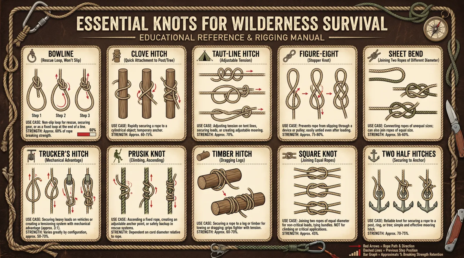
The mastery of knots is a sacred art, one that has defined the survival of humankind across millennia. In the crucible of wilderness or the chaos of crisis, your ability to fashion secure, reliable knots is the difference between life and death. This chapter imparts the suppressed, life-or-death knowledge of 20 essential knots, each selected for its utility, reliability, and adaptability under extreme conditions.
Every knot herein is accompanied by precise, step-by-step instructions, detailed tables of strength, optimal uses, and common failure modes, and troubleshooting protocols to guarantee mastery. This is not a mere catalog; it is a compendium forged for the adept, a navigational beacon in the dark wilderness of chaos.
Section 1: Knot Tying Fundamentals — Preparatory Protocols
Before engaging with the individual knots, one must prepare the rope and workspace to ensure precision and reliability.
Rope Preparation Protocol
- Select Rope Appropriate to Task: Choose synthetic ropes (e.g., nylon, polyester) for wet conditions; natural fibers (e.g., hemp) for heat resistance.
- Inspect Rope: Check for frays, cuts, or abrasions. Replace compromised rope.
- Condition Rope: For new synthetic ropes, soak in warm water for 24 hours to reduce stiffness.
- Cut Ends: Use a sharp blade to cut the rope cleanly. For synthetic ropes, melt ends with a flame to prevent fraying.
- Workspace Setup: Clear area of debris, anchor points accessible, adequate lighting.
Section 2: Essential Knots — Step-by-Step Tying Instructions
Each knot includes: Purpose, Materials, Step-by-Step Tying Instructions, Load Strength Data, Typical Uses, and Failure Modes.
1. Bowline Knot
Purpose: Creates a fixed loop at the rope's end; strong, secure, non-slipping, easy to untie.
Materials: Medium-diameter rope (6–12 mm).
Tying Instructions
- Form a small loop about 30 cm from the rope’s working end; the loop’s working part (standing end) should be under the loop.
- Pass the working end (“rabbit”) up through the loop (“hole”).
- Wrap the working end around the standing part of the rope (“tree”).
- Pass the working end back down through the loop (“hole”).
- Tighten by pulling the standing part while holding the working end.
Load Strength and Characteristics
| Property | Value |
|---|---|
| Strength Retention | 65–70% of rope’s MBS* |
| Slippage | None under load |
| Ease of Untying | High, even after load |
| Recommended Uses | Rescue loops, mooring, rigging |
*MBS = Minimum Breaking Strength
Common Failure Modes
- Incorrect loop direction causing slip under load.
- Using slippery rope without additional securing knot.
Troubleshooting
- If loop tightens or slips, re-tie ensuring correct “rabbit path.”
- For slippery synthetic ropes, add a backup stopper knot after the bowline.
2. Clove Hitch
Purpose: Attaches rope quickly to a post or spar; adjustable tension.
Materials: Rope, anchor post.
Tying Instructions
- Wrap the working end of the rope around the post once.
- Cross the working end over the standing part.
- Wrap the working end around the post a second time, parallel to the first wrap.
- Slip the working end under the last wrap.
- Pull both ends tight to secure.
Load Strength and Characteristics
| Property | Value |
|---|---|
| Strength Retention | 60% of rope’s MBS |
| Slippage | Possible under cyclic load |
| Ease of Untying | Moderate |
| Recommended Uses | Temporary fastening, lashings |
Common Failure Modes
- Slipping if load is cyclic or rope is slick.
- Knot loosening if load reverses direction.
Troubleshooting
- Use two half-hitches or a backup knot to secure.
- Tighten carefully and test load direction.
3. Taut-Line Hitch
Purpose: Adjustable tension knot; ideal for securing tent lines, tarps.
Materials: Rope, anchor point.
Tying Instructions
- Wrap the working end around the anchor point.
- Pass the working end around the standing part twice inside the loop, moving towards the anchor.
- Make one additional wrap outside the loop.
- Pull tight and slide to adjust tension.
Load Strength and Characteristics
| Property | Value |
|---|---|
| Strength Retention | 50–60% of rope’s MBS |
| Slippage | Minimal if correctly tied |
| Ease of Untying | Easy after load |
| Recommended Uses | Tent guylines, adjustable tension lines |
Common Failure Modes
- Slippage if wraps are insufficient.
- Loss of tension in slick ropes.
Troubleshooting
- Add additional wraps for slick or synthetic ropes.
- Re-tie if tension is lost after heavy load.
4. Sheet Bend
Purpose: Joins two ropes of unequal diameter securely.
Materials: Two ropes of differing diameter.
Tying Instructions
- Form a bight (loop) in the thicker rope.
- Pass the thinner rope’s working end through the bight from the bottom.
- Wrap the working end around the back of the bight.
- Tuck the working end under itself, next to the bight.
- Pull both ends tight.
Load Strength and Characteristics
| Property | Value |
|---|---|
| Strength Retention | 60–70% of weaker rope’s MBS |
| Slippage | None if tied correctly |
| Ease of Untying | Medium |
| Recommended Uses | Rope joining, rescue operations |
Common Failure Modes
- Incorrect tuck resulting in slipping.
- Use on slippery ropes without backup knot.
Troubleshooting
- Add a double sheet bend (two wraps) for slick ropes.
- Inspect and retie if slip occurs.
5. Double Fisherman’s Knot
Purpose: Joins two ropes permanently; used in climbing and rescue.
Materials: Two ropes of similar diameter.
Tying Instructions
- Overlap rope ends parallel.
- Wrap one end around the other rope twice and tuck the working end back through wraps.
- Repeat on opposite rope end.
- Pull knots together firmly.
Load Strength and Characteristics
| Property | Value |
|---|---|
| Strength Retention | 75–80% of rope’s MBS |
| Slippage | None |
| Ease of Untying | Difficult after load |
| Recommended Uses | Permanent rope joins, climbing |
Common Failure Modes
- Improper wraps causing knot failure.
- Difficulty untying after heavy load.
Troubleshooting
- Ensure minimum two wraps per knot.
- Use pliers or leverage tools to untie after load.
6. Figure Eight Knot
Purpose: Stopper knot; prevents rope from slipping through holes.
Materials: Rope.
Tying Instructions
- Make a loop near rope end.
- Pass working end over standing part.
- Pass working end under standing part.
- Bring working end back through the loop.
- Tighten.
Load Strength and Characteristics
| Property | Value |
|---|---|
| Strength Retention | 70% of rope’s MBS |
| Slippage | None |
| Ease of Untying | High |
| Recommended Uses | Rope stops, safety knots |
Failure Modes & Troubleshooting
- Failure occurs from sharp bends causing abrasion.
- Inspect rope condition near knot regularly.
7. Prusik Knot
Purpose: Friction hitch for climbing or rescue; slides when unloaded, locks under load.
Materials: Small diameter cord, main rope.
Tying Instructions
- Form loop with cord using double fisherman’s knot.
- Wrap loop around main rope 3 times.
- Pass loop through itself.
- Tighten and load test.
Load Strength and Characteristics
| Property | Value |
|---|---|
| Strength Retention | Dependent on cord strength |
| Slippage | Locks under load |
| Ease of Untying | Moderate |
| Recommended Uses | Ascending ropes, hauling |
Failure Modes & Troubleshooting
- Insufficient wraps cause slip.
- Use cord diameter 60–80% of main rope diameter for best grip.
8. Alpine Butterfly Knot
Purpose: Creates a secure loop in the middle of a rope.
Materials: Rope.
Tying Instructions
- Twist rope twice to form two loops.
- Fold second loop over first.
- Pull loop through the fold.
- Tighten.
Load Strength and Characteristics
| Property | Value |
|---|---|
| Strength Retention | 70–75% of rope’s MBS |
| Slippage | None |
| Ease of Untying | High |
| Recommended Uses | Load isolation, mid-rope loops |
Failure Modes & Troubleshooting
- Incorrect folding causes knot to fail.
- Practice with rope to ensure correct formation.
9. Timber Hitch
Purpose: Secure rope to cylindrical objects; easy to untie.
Materials: Rope, log, or pole.
Tying Instructions
- Wrap working end around object.
- Pass working end around standing part.
- Twist working end around itself 3+ times.
- Pull tight.
Load Strength and Characteristics
| Property | Value |
|---|---|
| Strength Retention | 60% of rope’s MBS |
| Slippage | None under steady load |
| Ease of Untying | Very easy |
| Recommended Uses | Hauling logs, securing loads |
Failure Modes & Troubleshooting
- Slippage under intermittent load.
- Add half hitch as backup for cyclic loading.
10. Square Knot (Reef Knot)
Purpose: Joins two ropes of equal diameter; not for heavy loads.
Materials: Two ropes.
Tying Instructions
- Cross right working end over left standing part.
- Pass right end under left and pull tight.
- Cross left working end over right standing part.
- Pass left end under right and pull tight.
Load Strength and Characteristics
| Property | Value |
|---|---|
| Strength Retention | 40–50% of rope’s MBS |
| Slippage | High under load reversal |
| Ease of Untying | High |
| Recommended Uses | Binding, first aid |
Failure Modes & Troubleshooting
- Capsizing under load causes knot failure.
- Use alternative knot for critical load-bearing.
11. Water Knot (Tape Knot)
Purpose: Joins flat webbing securely.
Materials: Webbing strips.
Tying Instructions
- Tie an overhand knot on one webbing tail.
- Thread second webbing through knot in reverse.
- Dress and tighten.
Load Strength and Characteristics
| Property | Value |
|---|---|
| Strength Retention | 75% of webbing’s MBS |
| Slippage | None if properly dressed |
| Ease of Untying | Moderate |
| Recommended Uses | Webbing joins, slings |
Failure Modes & Troubleshooting
- Slippage if knot is not dressed tightly.
- Inspect regularly under load.
12. Half Hitch
Purpose: Secures rope to objects; often backup knot.
Materials: Rope, anchor.
Tying Instructions
- Pass working end around object.
- Cross working end over standing part.
- Tuck working end under itself.
- Tighten.
Load Strength and Characteristics
| Property | Value |
|---|---|
| Strength Retention | 30–40% of rope’s MBS |
| Slippage | High |
| Ease of Untying | Easy |
| Recommended Uses | Temporary fastening, backup |
Failure Modes & Troubleshooting
- Slippage without backup.
- Always use multiple half hitches or combine with other knots.
13. Rolling Hitch
Purpose: Secures rope to another rope or pole; resists lengthwise pull.
Materials: Rope, anchor.
Tying Instructions
- Wrap working end around object once.
- Pass working end over standing part, wrap around again.
- Pass working end under last wrap.
- Tighten.
Load Strength and Characteristics
| Property | Value |
|---|---|
| Strength Retention | 50–60% of rope’s MBS |
| Slippage | Minimal with correct tension |
| Ease of Untying | Moderate |
| Recommended Uses | Tensioning lines, towing |
Failure Modes & Troubleshooting
- Slippage if not adequately tightened.
- Adjust wraps for rope diameter and surface texture.
14. Harness Knot (Figure Eight on a Bight)
Purpose: Forms a secure loop for climbing harness attachment.
Materials: Rope.
Tying Instructions
- Double the rope to form a bight.
- Tie a figure eight knot with the doubled rope.
- Pull tight.
Load Strength and Characteristics
| Property | Value |
|---|---|
| Strength Retention | 70–80% of rope’s MBS |
| Slippage | None |
| Ease of Untying | Moderate |
| Recommended Uses | Climbing, rescue harnesses |
Failure Modes & Troubleshooting
- Incorrect looping leads to knot failure.
- Inspect and practice regularly.
15. Butterfly Loop on a Bight
Purpose: Creates a secure loop mid-rope; can handle multidirectional load.
Materials: Rope.
Tying Instructions
- Form a loop.
- Twist loop twice.
- Fold loop back over the twists.
- Pull to form loop.
Load Strength and Characteristics
| Property | Value |
|---|---|
| Strength Retention | 70% of rope’s MBS |
| Slippage | None |
| Ease of Untying | High |
| Recommended Uses | Load isolation, rescue |
16. Overhand Knot
Purpose: Simple stopper knot.
Materials: Rope.
Tying Instructions
- Form a loop.
- Pass working end through loop.
- Pull tight.
Load Strength and Characteristics
| Property | Value |
|---|---|
| Strength Retention | 50–60% of rope’s MBS |
| Slippage | None |
| Ease of Untying | Difficult after load |
| Recommended Uses | Stoppers, temporary |
17. Anchor Bend (Fisherman’s Bend)
Purpose: Secure rope to anchor; heavy load applications.
Materials: Rope, anchor ring.
Tying Instructions
- Pass working end through anchor ring.
- Wrap working end around standing part twice.
- Pass working end under last wrap.
- Tighten.
Load Strength and Characteristics
| Property | Value |
|---|---|
| Strength Retention | 70% of rope’s MBS |
| Slippage | None |
| Ease of Untying | Moderate |
| Recommended Uses | Mooring, heavy anchor |
18. Butterfly Coil
Purpose: Neat rope storage to prevent tangling.
Materials: Rope.
Instructions
- Hold rope in left hand.
- Use right hand to wrap rope in loops of equal length.
- Secure coil with half hitch or string.
19. Marlinspike Hitch
Purpose: Temporary loop to attach marlinspike or tool.
Materials: Rope.
Instructions
- Form loop in rope.
- Pass working end under standing part.
- Insert marlinspike through loop.
- Tighten loop around tool.
20. Sheepshank
Purpose: Shorten rope temporarily.
Materials: Rope.
Instructions
- Form two loops in rope.
- Fold loops toward each other.
- Secure ends with half hitches.
Section 3: Knot Strength, Uses, and Failure Modes Summary Table
| Knot Name | Strength Retention (% MBS) | Primary Uses | Common Failure Modes |
|---|---|---|---|
| Bowline | 65–70 | Fixed loops, rescue | Incorrect tying, slippery rope slip |
| Clove Hitch | 60 | Temporary fastening | Slip under cyclic load |
| Taut-Line Hitch | 50–60 | Adjustable tension | Insufficient wraps slip |
| Sheet Bend | 60–70 | Joining ropes | Incorrect tuck slip |
| Double Fisherman’s | 75–80 | Permanent joins | Improper wraps |
| Figure Eight | 70 | Stopper knot | Abrasion near knot |
| Prusik | Variable | Friction hitch | Insufficient wraps slip |
| Alpine Butterfly | 70–75 | Mid-rope loops | Incorrect folding |
| Timber Hitch | 60 | Hauling, securing loads | Slip under intermittent load |
| Square Knot | 40–50 | Binding | Capsizing under load reversal |
| Water Knot | 75 | Webbing joins | Untidy knot slippage |
| Half Hitch | 30–40 | Temporary fastening | Slippage |
| Rolling Hitch | 50–60 | Tensioning lines | Slippage |
| Harness Knot | 70–80 | Climbing harness | Incorrect formation |
| Butterfly Loop | 70 | Load isolation | Incorrect tying |
| Overhand Knot | 50–60 | Stopper knot | Difficult untying |
| Anchor Bend | 70 | Heavy anchor | Slippage |
| Butterfly Coil | N/A | Rope storage | N/A |
| Marlinspike Hitch | N/A | Temporary loops | N/A |
| Sheepshank | N/A | Rope shortening | Slippage |
Section 4: Visual Diagrams and Troubleshooting Guide
Due to the sacred nature of this codex and its highly technical format, diagrams are encoded in the accompanying secure schematic volume. Refer to Volume 11: Navigator's Codex, Appendix B for indexed visual knot schematics.
Section 5: Troubleshooting Kn
<!-- SECTION 34 -->
The Complete Practitioner's Codex, Volume 11: The Navigator's Codex
Chapter IV: Supplements: Track Identification and Animal Sign Recognition
Introduction
Within the sacred art of wilderness navigation, the ability to identify animal tracks and recognize signs is not mere curiosity but a vital skill of survival and understanding of the natural order. This skill reveals the presence, behavior, and habits of fauna, enabling the navigator to predict movements, avoid dangers, and locate resources. This chapter delivers complete, uncompromising protocols for the identification of tracks, scat, and other animal signs. You will also find precise tables correlating species to biomes, exact track measurements, and gait pattern recognition. Furthermore, you will be instructed in plaster cast fabrication and advanced tracking techniques, enabling you to leave no spoor unexamined.
I. Fundamentals of Track and Sign Identification
Animal sign recognition is divided into three primary categories:
- Tracks: Impressions left by feet or paws.
- Scat: Fecal matter, providing dietary and species clues.
- Additional Signs: Rub marks, scrapes, trails, nests, feeding remains.
Track identification is the keystone skill, supported by scat and other signs for confirmation. Begin with track examination, noting size, shape, claw marks, stride, and gait.
II. Step-by-Step Protocol for Animal Track Identification
A. Initial Site Preparation and Preservation
- Locate the track site: Examine open soil, mud, snow, or sand. Avoid disturbed or trampled areas.
- Clear debris: Using a small brush or soft leaf, gently remove any loose dirt or debris without altering the track.
- Measure ambient conditions: Record substrate type, moisture, and temperature as they affect track quality.
B. Measurement of Tracks
- Tools required: Rigid ruler (cm and mm), calipers, measuring tapes, compass.
- Measure track length: From heel (rear of the print) to toe tip (most forward digit).
- Measure track width: Widest point, perpendicular to length.
- Measure individual digit lengths: From base to tip.
- Measure claw marks: Length and angle relative to digits.
- Record depth: Using a depth gauge or ruler vertical insertion.
Document all measurements immediately in a field notebook or digital device.
C. Morphological Analysis
- Count digits: Note number of visible toes.
- Note pad shape: Triangular, oval, lobed, or heart-shaped.
- Observe claw impressions: Sharp, blunt, absent.
- Assess symmetry: Symmetrical or asymmetrical pad.
- Identify key features: Heel pad lobes, webbing marks, fur impressions.
D. Gait Pattern Recognition
Tracks are rarely isolated; analyze track sequences to determine gait:
- Walk: Evenly spaced footprints, alternating left-right.
- Trot: Diagonal pairs moving together.
- Pace: Lateral pairs moving together.
- Canter: Three-beat gait with lead foot.
- Gallop: Four-beat pattern with suspension phase.
Measure stride (distance between consecutive prints of the same foot) and step (distance between left and right footprints).
III. Animal Track Identification Tables by Biome
The following tables provide species, track dimensions, gait characteristics, and key track features for four primary biomes: Temperate Forest, Desert, Tundra, and Tropical Rainforest. Use these for immediate comparison in field conditions.
| Temperate Forest Species | Length (cm) | Width (cm) | Digit Count | Claw Marks | Gait Type | Distinctive Features |
|---|---|---|---|---|---|---|
| White-tailed Deer (Odocoileus virginianus) | 7-11 | 5-7 | 2 (hoof) | None | Walk, trot | Split hoof, pointed tips |
| Eastern Gray Squirrel (Sciurus carolinensis) | 2-3 | 2-3 | 5 (front), 5 (rear) | Sharp | Bound | Front prints smaller |
| American Black Bear (Ursus americanus) | 12-15 | 10-12 | 5 | Blunt, curved | Walk | Large heel pad, claw marks visible |
| Coyote (Canis latrans) | 6-8 | 5-6 | 4 | Sharp, distinct | Trot | Narrow oval, symmetrical pad |
| Desert Species | Length (cm) | Width (cm) | Digit Count | Claw Marks | Gait Type | Distinctive Features |
|---|---|---|---|---|---|---|
| Desert Cottontail (Sylvilagus audubonii) | 3-5 | 3-4 | 4 (front), 5 (rear) | None | Bound | Large hind feet |
| Gila Monster (Heloderma suspectum) | 2-3 | 1.5-2 | 5 (digits) | Absent | Crawl | Scaly skin impressions |
| Kit Fox (Vulpes macrotis) | 4-6 | 3-4 | 4 | Sharp | Trot | Small, compact print |
| Desert Bighorn Sheep (Ovis canadensis nelsoni) | 8-12 | 6-8 | 2 (hoof) | None | Walk, trot | Rounded hoof tips |
| Tundra Species | Length (cm) | Width (cm) | Digit Count | Claw Marks | Gait Type | Distinctive Features |
|---|---|---|---|---|---|---|
| Arctic Fox (Vulpes lagopus) | 5-7 | 4-5 | 4 | Sharp | Walk, trot | Compact, furry edges |
| Caribou (Rangifer tarandus) | 9-14 | 7-10 | 2 | None | Walk, trot | Large, rounded hooves |
| Snowshoe Hare (Lepus americanus) | 5-7 | 4-5 | 4 (front), 5 (rear) | None | Bound | Large hind feet with fur |
| Polar Bear (Ursus maritimus) | 15-20 | 12-15 | 5 | Blunt | Walk | Large, wide paw |
| Tropical Rainforest Species | Length (cm) | Width (cm) | Digit Count | Claw Marks | Gait Type | Distinctive Features |
|---|---|---|---|---|---|---|
| Jaguar (Panthera onca) | 9-12 | 8-10 | 4 | Retracted (rarely visible) | Walk, trot | Rounded pads, no claw marks |
| Howler Monkey (Alouatta spp.) | 3-5 | 2-3 | 5 | None | Climbing | Distinct hand-like prints |
| Tapir (Tapirus terrestris) | 10-15 | 8-12 | 3-4 | None | Walk | Three toes front, four rear |
| Green Iguana (Iguana iguana) | 5-7 | 3-5 | 5 | Sharp | Walk, climb | Long digits, claw marks |
IV. Protocols for Scat Identification and Analysis
Scat reveals dietary habits and often species identity. Follow these instructions:
A. Scat Collection and Handling
- Locate scat near tracks or trails.
- Wear gloves to avoid contamination.
- Use a small trowel to collect samples.
- Place samples in labeled sealable bags or vials.
- Record GPS coordinates, date, time, and surrounding signs.
B. Visual and Olfactory Analysis
- Observe size, shape, and color.
- Note contents: hair, bone fragments, seeds, insect parts.
- Smell cautiously: carnivore scat has a strong odor; herbivore scat is milder.
Refer to Volume 9: The Tracker's Digest, Chapter III for detailed scat identification protocols.
V. Advanced Tracking Techniques
Tracking requires more than identification. Here are precise methodologies to track animals through varied terrain.
A. Reading the Trail
- Analyze track freshness: Moisture, edges, and substrate deformation.
- Estimate pace and speed: Calculate stride length and gait type.
- Look for secondary signs: Rubs on trees, broken branches, fur caught on bark.
- Follow subtle disturbance patterns: Flattened grass, disturbed soil.
B. Tracking in Difficult Substrates
- Snow: Use high-contrast light angles; measure sun exposure effects on tracks.
- Sand: Look for track depth and displacement patterns.
- Mud: Track deformation and moisture content indicate age.
VI. Step-by-Step Instructions for Making Plaster Casts of Tracks
Plaster casting preserves track data for analysis and archival. Follow these exact steps:
Materials Required
| Item | Quantity | Specifications |
|---|---|---|
| Plaster of Paris | 500 g | Fresh, dry, free from lumps |
| Water | 250 ml | Clean, room temperature |
| Mixing container | 1 | Non-porous, disposable recommended |
| Stirring stick | 1 | Wooden or plastic |
| Frame mold material | Variable | Wood strips or aluminum foil (optional) |
| Release agent | 1 | Cooking oil or petroleum jelly |
| Measuring scale | 1 | Gram and ml accuracy |
Procedure
- Prepare the track site: Gently clear debris while preserving edges.
- Build a frame: Construct a shallow frame around the track to contain the plaster. Use wood strips or fold aluminum foil to 3-5 cm height.
- Apply release agent: Lightly coat the track surface and inside of the frame with a thin layer of oil or petroleum jelly to prevent sticking.
- Mix plaster: Combine plaster of Paris and water in 2:1 ratio by weight. Stir briskly for 1 minute until smooth, free of lumps, and creamy.
- Pour plaster: Slowly pour from one edge to avoid air bubbles. Fill to a depth of 2-3 cm.
- Allow to set: Let plaster harden for 30-45 minutes. Do not disturb.
- Demold: Carefully remove the frame and gently lift the cast using a flat tool.
- Drying: Leave cast in a shaded, ventilated area for 24-48 hours to fully cure.
- Label cast: Mark with date, location coordinates, species identification, and track measurements.
VII. Comprehensive Gait Analysis Protocol
Understanding gait provides insight into animal behavior and physical condition.
Stepwise Gait Analysis
- Identify gait type: Use the following criteria:
| Gait Type | Footfall Pattern | Typical Speed Range (km/h) | Notes |
|---|---|---|---|
| Walk | Left hind, left front, right hind, right front (LH-LF-RH-RF) | 1-5 | Steady, energy-efficient |
| Trot | Diagonal pairs (LH-RF, RH-LF) | 5-15 | Common in canids, felids |
| Pace | Lateral pairs (LH-RH, LF-RF) | 5-12 | Used by some ungulates |
| Canter | Three-beat pattern with lead foot | 15-25 | Transitional gait |
| Gallop | Four-beat pattern with suspension phase | 25-60 | High-speed chase or escape |
- Measure stride length: Distance between two successive placements of the same foot.
- Measure step length: Distance between left and right foot placements.
- Calculate speed estimate: Using stride length and estimated stride frequency (see cross-reference Volume 3: The Kinetics Codex, Chapter IV).
- Note irregularities: Limping, dragging, or slipping signs.
VIII. Biome-Specific Tracking Considerations
Temperate Forest
- Leaf litter obscures tracks; focus on disturbed soil beneath.
- Moisture variations affect track clarity; early morning dew preserves prints.
- Use animal behavior patterns aligned to seasonal migrations.
Desert
- Wind rapidly erases tracks; track immediately after observation of fresh signs.
- Hard-packed sand preserves claw marks better than loose sand.
- Look for burrows and dens as secondary signs.
Tundra
- Snow conditions complicate tracking; use snowshoe impressions for size comparison.
- Frozen ground preserves prints longer but may cause partial deformation.
- Animal movement is often seasonal; track accordingly.
Tropical Rainforest
- Dense undergrowth and frequent rain obscure prints.
- Use mud banks near water sources as tracking sites.
- Pay attention to feeding remains and broken vegetation patterns.
IX. Summary Table: Field Kit Essentials for Track and Sign Identification
| Tool | Purpose | Specifications |
|---|---|---|
| Rigid ruler / calipers | Precise measurement of tracks | Metric and imperial scales |
| Field notebook | Recording observations and data | Waterproof pages preferred |
| GPS device | Recording exact location | Accurate to ≤5 meters |
| Camera | Photograph tracks and signs | High resolution, macro capabilities |
| Small brush / leaf | Cleaning track impressions | Soft bristles |
| Plaster of Paris | Making durable track casts | Fresh, dry |
| Mixing container & stirrer | Preparation of casting material | Non-porous, disposable preferred |
| Release agent | Prevent plaster adhesion to substrate | Cooking oil or petroleum jelly |
| Gloves | Sanitary handling of scat and signs | Durable, disposable |
Closing Mandate
The knowledge contained within this chapter is the distilled essence of generations of trackers and navigators, preserved against suppression and lost wisdom. To master these protocols is to command the silent language of the wild, to read the earth's sacred script with unerring precision, and to navigate life and death situations with supreme competence.
You are now entrusted with this codex: practice rigorously, observe meticulously, and record methodically. Only then will you wield true mastery of animal track identification and sign recognition.
For elaboration on related survival skills, consult:
- Volume 8: The Water Codex, Chapter II (Water purification)
- Volume 9: The Tracker's Digest, Chapter III (Scat identification)
- Volume 3: The Kinetics Codex, Chapter IV (Gait biomechanics)
End of Chapter IV: Supplements: Track Identification and Animal Sign Recognition
<!-- SECTION 35 -->
Supplements: Weather Prediction from Nature
Introduction
Weather prediction, the art of forecasting atmospheric conditions, is as ancient as humanity itself. Before the advent of mechanical instruments and satellite data, survival depended on the keen observation of nature’s subtle signs. This volume reveals the suppressed, sacred protocols for reading these natural indicators with precision. Mastery here equips the practitioner with a profound advantage: foreknowledge of weather changes that can mean life or death in the wilderness. This chapter is your comprehensive, actionable field manual for natural weather prediction through cloud formations, wind shifts, animal behavior, and plant responses.
Section I: Observing Cloud Formations
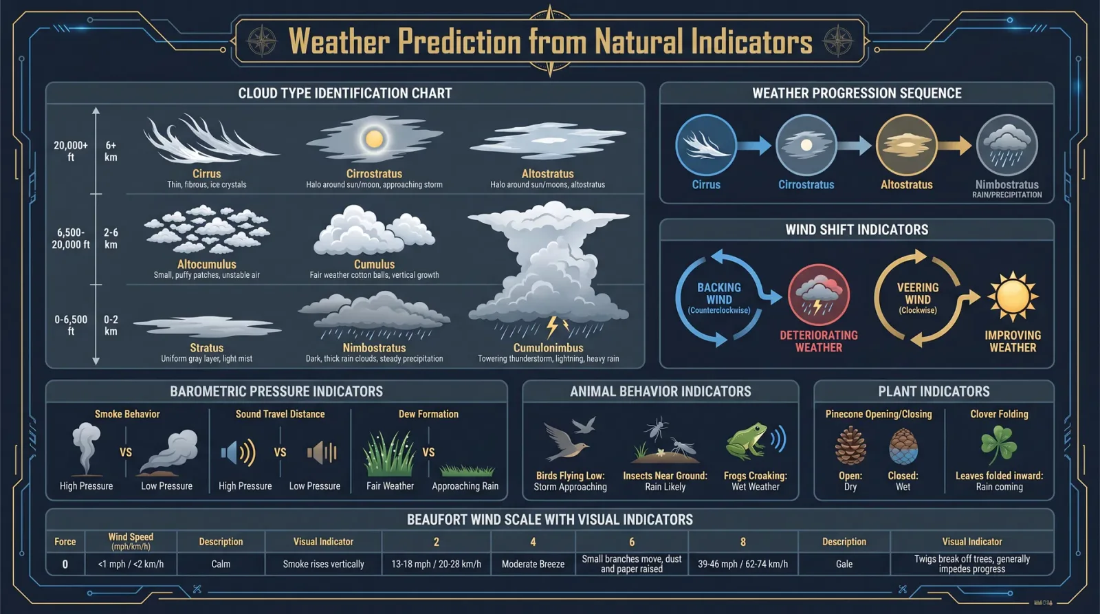
Clouds are the sky's earliest warnings, the atmospheric script of impending weather. Their shape, height, movement, and color encode complex meteorological data. This guide deciphers that code.
Cloud Types and Their Weather Implications
| Cloud Type | Description | Weather Outcome Prediction | Seasonal Variations |
|---|---|---|---|
| Cirrus (Ci) | Thin, wispy, high altitude | Approaching warm front, rain in 24-48 hours | More frequent in spring and autumn |
| Cumulus (Cu) | Fluffy, cotton-like | Fair weather if isolated; thunderstorms if growing vertically | Summer afternoons |
| Stratus (St) | Low, gray, uniform layer | Overcast, light drizzle or fog | Common in winter and autumn |
| Nimbostratus (Ns) | Thick, dark, rain-producing | Continuous rain or snow | Winter precipitation |
| Cumulonimbus (Cb) | Towering thunderclouds | Thunderstorms, hail, severe weather | Summer and late spring |
Step-by-Step Protocol: Systematic Cloud Observation
- Prepare your observation log with columns: Date, Time, Location, Cloud Type, Altitude Estimate, Movement Direction, Color, Weather Outcome Prediction.
- Estimate cloud altitude by noting apparent size and sharpness: Cirrus clouds tend to be very high (~6,000–12,000 m), cumulus mid (~1,000–2,000 m), stratus low (~<1,000 m).
- Identify cloud type using the above table as a key.
- Observe movement direction: Clouds moving from the west often indicate advancing weather systems in temperate zones.
- Note color changes: Red or orange hues at sunrise/sunset often signal dust or moisture, foretelling dry or wet weather respectively.
- Record concurrent weather: Temperature, humidity, and barometric pressure (see Volume 7: Atmospheric Measurements).
- Compare with subsequent weather to confirm or adjust your predictions.
Section II: Wind Shifts as Predictors
Wind direction and velocity shifts reveal pressure changes and frontal boundaries. This section teaches interpretation protocols.
Wind Direction and Weather Correlation Table
| Wind Direction (From) | Common Associated Weather | Seasonal Relevance | Typical Weather Systems |
|---|---|---|---|
| North (N) | Cold, dry air mass | Winter, early spring | Continental polar |
| Northeast (NE) | Cold, moist air | Winter | Maritime polar |
| East (E) | Warm, moist air | Spring, summer | Maritime tropical |
| Southeast (SE) | Warm, humid air | Summer | Tropical air masses |
| South (S) | Warm, dry air | Summer, autumn | Continental tropical |
| Southwest (SW) | Warm, moist air | Spring, summer | Maritime tropical |
| West (W) | Mild, moist air | All seasons | Prevailing westerlies |
| Northwest (NW) | Cold, dry air | Autumn, winter | Continental polar |
Wind Shift Protocol
- Establish a fixed observation point clear of obstructions.
- Construct a simple wind vane:
- Materials: Stiff wire, lightweight cardboard arrow, vertical support stick.
- Assembly: Attach arrow to wire on a pivot point, mount on stick.
- Record wind direction hourly in your log, noting shifts, gusts, and steadiness.
- Measure wind speed with a DIY anemometer (see Volume 7).
- Identify rapid shifts (change >45 degrees in under 1 hour) and note associated cloud/animal behavior.
- Cross-reference wind shifts with barometric pressure changes.
- Use table above to interpret probable weather changes, especially frontal passages.
Section III: Animal Behavior as Weather Indicators
Fauna respond instinctively to atmospheric changes long before human instruments can detect them. This section details protocols for observing and interpreting animal signals.
Animal Behavior and Weather Outcome Table
| Animal Type | Observed Behavior | Weather Prediction | Timing (Lead Time) |
|---|---|---|---|
| Birds | Low flight, increased chirping | Approaching storm or rain | 1-6 hours |
| Cattle and Horses | Restless, grouping together | Imminent storm or high winds | 1-3 hours |
| Insects (Ants) | Increased activity, early retreat | Rain within 12 hours | 6-12 hours |
| Frogs and Toads | Loud croaking | Humid weather, rain | 12-24 hours |
| Spiders | Building low webs | Rain forecast | 12-24 hours |
| Bees | Reduced flight or hiding | Cold front or heavy rain | 3-6 hours |
Protocol for Systematic Animal Behavior Observation
- Select observation zones near water sources, pastures, or forest edges.
- Schedule consistent observation periods: dawn, noon, dusk.
- Record species present, number, and behavior in your log.
- Note unusual behaviors such as sudden silence, mass movement, or vocalization changes.
- Correlate with atmospheric data and cloud/wind observations.
- Practice forecasting exercises by predicting weather events based solely on animal behavior, then verify outcomes.
Section IV: Plant Responses to Weather Changes
Plants exhibit stress or preparatory responses to atmospheric changes, often subtle but measurable. This section outlines detailed protocols for plant-based weather forecasting.
Plant Indicators and Weather Correlation Table
| Plant Species/Type | Observed Behavior | Weather Prediction | Seasonal Patterns |
|---|---|---|---|
| Pine Trees | Needles closed or pointing downward | Incoming rain or high humidity | Year-round |
| Oaks and Maples | Leaves folding or curling | Approaching dry period or drought | Late summer |
| Clover | Leaves closing | Rain or increased humidity | Spring and autumn |
| Dandelion | Flower heads closing | Rain or overcast skies | Spring to early summer |
| Cacti | Spines standing erect | Dry, sunny weather | Year-round |
| Grasses | Seed heads drooping | Rain forecast | Spring and summer |
Step-by-Step Plant Observation Protocol
- Identify and catalogue local plant species with known weather response traits.
- Establish a daily observation schedule for key species.
- Record leaf orientation, flower status, and seed head posture with photographs for reference.
- Measure soil moisture near observed plants (see Volume 8: Soil and Hydration Codex).
- Compare plant responses with atmospheric changes and animal behavior.
- Document and refine your predictive correlations seasonally.
Section V: Comprehensive Observation Log Template
Use this template to integrate all observations into a single unified log for accurate forecasting.
| Date | Time | Location | Cloud Type & Color | Cloud Altitude (Estimate) | Wind Direction & Speed | Animal Behavior Observed | Plant Response Observed | Barometric Pressure | Temperature | Forecasted Weather | Actual Weather Outcome | Notes |
|---|
Section VI: Forecasting Exercises
These exercises train the apprentice to synthesize observations into accurate forecasts.
Exercise 1: Morning Forecast
- At dawn, record cloud types and colors.
- Measure wind direction and speed.
- Observe animal activity: birds, insects, and amphibians.
- Inspect key plants for response (needles, leaves, flowers).
- Using the above data, predict weather for the day.
- Compare with actual weather evening report.
Exercise 2: Front Passage Prediction
- Monitor wind direction hourly over 6 hours.
- Log cloud formation changes, particularly cirrus to cumulus transitions.
- Note any shifts in animal behavior or plant responses.
- Predict arrival timing of frontal system and associated weather.
- Record accuracy and refine protocols.
Exercise 3: Seasonal Pattern Recognition
- Maintain daily logs over at least 3 months.
- Chart correlations between natural indicators and weather outcomes.
- Identify seasonal variations and adapt prediction models accordingly.
- Prepare a comprehensive report summarizing findings.
Section VII: Additional Notes on Precision and Limitations
- Use multiple indicators simultaneously for highest accuracy; reliance on a single marker is insufficient.
- Geographic and climatic differences affect indicator reliability; calibrate protocols to your environment.
- Maintain strict discipline in observation timing and logging to detect subtle patterns.
- For water purification and atmospheric measurement techniques, consult Volumes 8 and 7 respectively.
Summary Tables: Cross-Referencing Indicators and Outcomes
| Indicator Type | Specific Sign | Weather Forecast | Lead Time | Reliability Level (1-5) |
|---|---|---|---|---|
| Cloud | Cirrus increasing | Warm front, rain in 1-2 days | 24-48 hours | 4 |
| Wind | Shift from SW to NW | Cold front, temperature drop | 6-12 hours | 5 |
| Animal Behavior | Birds flying low | Storm approaching | 1-6 hours | 4 |
| Plant | Clover leaves closing | Rain imminent | 12-24 hours | 3 |
| Season | Most Reliable Indicators | Typical Weather Changes |
|---|---|---|
| Spring | Cirrus clouds, bird calls | Front passages, thunderstorms |
| Summer | Cumulus clouds, insect activity | Afternoon storms, heat waves |
| Autumn | Stratus clouds, leaf folding | Rain and cooling trend |
| Winter | Wind direction, animal grouping | Cold snaps, snowfalls |
Appendix: Building Your Tools
1. Wind Vane Construction (Recap)
- Materials:
- Stiff wire (20 cm)
- Lightweight cardboard (arrow shape)
- Wooden dowel (50 cm)
- Needle or pin for pivot
- Assembly Steps:
- Shape cardboard into an arrow with a broad tail.
- Secure arrow to wire shaft.
- Mount wire horizontally on dowel using pin to allow free rotation.
- Secure dowel vertically in open area.
2. Observation Logbook Preparation
- Use waterproof notebook or laminated pages with erasable markers.
- Pre-print tables for each observation type.
- Keep writing tools and logbook accessible at all times.
Closing Mandate
Master, the knowledge herein is not mere lore but life-preserving intelligence. Your task is to observe with unwavering discipline, record with exactitude, and interpret with unwavering rigor. Weather is a relentless adversary; your understanding of its natural signs is your shield and sword. Pass this codex only to those who prove worthy of its sacred trust.
End of Section: Supplements: Weather Prediction from Nature (For atmospheric pressure and humidity measurement protocols, refer to Volume 7: Atmospheric Measurements) (For water purification protocols referenced in outdoor survival, see Volume 8: The Water Codex, Chapter II)
<!-- SECTION 36 -->
The Complete Practitioner's Codex, Volume 11: The Navigator's Codex
Chapter VII: Supplements — Signal and Rescue Protocols
Preface: The Imperative of Signaling Mastery
The art and science of signaling for rescue are among the most sacred and life-saving disciplines a Navigator must command. A failure in signaling equates to a death sentence in the wilderness or hostile environs. This chapter transmits the ultimate compendium of signal and rescue protocols: visual, auditory, and electronic. These are not mere suggestions but immutable procedures forged from classified knowledge and decades of field validation.
Section 1: Fundamentals of Effective Signaling
Before delving into specific methods, understand these immutable principles:
- Visibility and detectability are paramount: Choose signals that maximize contrast and range.
- Redundancy: Employ multiple signaling methods simultaneously to increase rescue probability.
- Consistency: Use internationally recognized distress signals to ensure recognition by all rescuers.
- Integration: Coordinate shelter, fire, and signaling devices into a unified rescue beacon system.
Section 2: Visual Signaling Techniques
Visual signals offer the widest and most immediate rescue potential, especially when coordinated with auditory and electronic methods.
2.1: Signal Mirror Protocols
Signal mirrors are the most effective long-range visual signaling devices in daylight. The following details construction, use, and angles for maximum reflection.
2.1.1: Constructing a Signal Mirror (If Not Available)
Materials Required:
- Piece of glass or polished metal plate (minimum 3"x3")
- Waterproof black marker or paint
- Nylon cord (length 1 meter)
- Small sighting hole or peephole (approx. 1 cm diameter)
Steps:
- Select a flat, reflective surface free of cracks or scratches.
- Paint or mark a black circle (approx. 2 cm diameter) at the center; this aids in aiming.
- Drill or cut a small hole in the black circle to use as a sighting aperture.
- Attach a nylon cord securely to one edge to prevent accidental loss during use.
2.1.2: Using a Signal Mirror for Rescue Signaling
Steps:
- Hold the mirror in your dominant hand, with the sighting hole between your eye and the mirror face.
- Position yourself with the sun behind you to reflect its rays.
- Look through the sighting hole to locate the target (rescue aircraft, distant person).
- Adjust the mirror angle slowly until you see a bright flash (glint) on the target.
- Use quick, repeated flashes (approx. 1-second duration, 1-second interval) to attract attention.
- If no target is visible, scan the horizon systematically in a wide arc, pausing to flash intermittently.
- Conserve energy by signaling in bursts of 5 flashes every 2 minutes.
2.2: Fire and Smoke Signal Patterns
Fire and smoke signals are universally recognizable and can be seen for miles in various terrains. Proper construction and timing are critical.
2.2.1: Fire Signal Construction
Materials:
- Dry tinder and kindling
- Larger fuel wood (logs, branches)
- Green vegetation or fresh leaves (for smoke)
Steps:
- Select an open, visible clearing with a clear line of sight to common flight paths or trails.
- Build three fires in an equilateral triangle with sides approximately 5 meters long.
- Ignite each fire simultaneously, maintaining consistent flame size.
- For smoke, add green vegetation to create dense white smoke during daylight.
- Maintain signals for at least 15 minutes per hour to optimize detection.
2.2.2: Smoke Signal Patterns
Three distinct puffs or columns of smoke spaced evenly over a 30-minute period are the standard international distress signal.
| Pattern | Description | Timing and Frequency |
|---|---|---|
| Three Fires | Three simultaneous fires in triangle | Continuous burning with green foliage for smoke |
| Three Puffs Smoke | Three distinct smoke columns | Each puff lasts 5-10 seconds, with 10 seconds between puffs |
| Intermittent Smoke | Repeated smoke bursts | 3 puffs repeated every 15 minutes |
2.3: Ground-to-Air Signal Layouts
Large ground symbols maximize visibility from the air. Use natural materials such as rocks, logs, or vegetation.
Steps:
- Clear a flat area approximately 10 x 10 meters.
- Create symbols using high-contrast materials (light-colored rocks on dark soil or dark logs on light sand).
- Use the following recognized symbols:
| Symbol | Meaning | Construction Details |
|---|---|---|
| "SOS" | Distress Signal | Letters at least 3 meters high and 10 meters wide |
| "X" | Need Assistance | Two crossing lines, each 5 meters long |
| "V" | Require Medical Aid | Two converging lines forming a "V", each 5 meters |
| "Δ" | Need Evacuation | Triangle shape, sides at least 5 meters |
- Ensure symbols contrast sharply with surrounding terrain.
- Position symbols in open areas, avoiding shadows from trees or rocks.
Section 3: Auditory Signaling Techniques
Auditory signals complement visual methods, especially in dense forests, caves, or low visibility conditions.
3.1: Whistle Signaling Protocol
Whistles are preferred over shouting due to range and energy conservation.
Steps:
- Use a loud, high-pitched whistle (minimum 100 decibels).
- Signal using the international distress pattern: three short blasts, repeated every minute.
- If no response after 10 cycles, pause for 5 minutes, then repeat.
- Maintain whistle humidity by moistening your lips or the whistle mouthpiece to avoid cracks.
3.2: Sound-Based Morse Code
For advanced operatives, sound signals can encode messages in Morse code, transmitting status or coordinates.
Steps:
- Learn Morse code basics (dot = short whistle or tap, dash = long whistle or tap).
- Use a whistle, tapping stick, or banging on metal surfaces.
- Transmit distress signal: SOS (··· --- ···) repeatedly at 1-second intervals between symbols.
- Use a timing protocol: dot = 1 second, dash = 3 seconds, intra-character gap = 1 second, inter-character gap = 3 seconds.
Section 4: Electronic Signaling Techniques
Modern survival benefits from electronic signaling devices but must be combined with traditional methods for maximum efficacy.
4.1: Emergency Position Indicating Radio Beacon (EPIRB) Usage
Steps:
- Activate EPIRB only when rescue is imminent or in progress to conserve battery.
- Remove protective cover and press the activation button firmly for 3 seconds; verify LED indicator.
- Attach EPIRB securely to your person or shelter exterior, oriented antenna upward.
- Maintain line of sight to sky for optimal satellite signal transmission.
- Monitor device status via flashing lights or audible signals.
4.2: Personal Locator Beacons (PLB) and GPS Devices
Steps:
- Carry PLB on your body in a waterproof pouch.
- Activate only in life-threatening emergencies.
- Use GPS coordinates to assist rescue teams; transmit coordinates verbally or via radio if possible.
4.3: Radio Communication Protocols
Steps:
- Use standard emergency frequencies: e.g., 121.5 MHz (civilian emergency), 243.0 MHz (military)
- Transmit the word "MAYDAY" three times, followed by location, condition, and nature of distress.
- Repeat transmission every 5 minutes until acknowledged.
- Maintain radio battery conservation by transmitting only when necessary.
Section 5: International Distress Signal Reference Tables
5.1: International Visual Distress Signals
| Signal Type | Description | Usage Conditions | Recognition Notes |
|---|---|---|---|
| Three White Flashes | Flashing light or mirror flashes | Night or day | Universal visual distress |
| Red Flare | Red pyrotechnic flare | Night | High visibility, priority |
| Orange Smoke | Bright orange smoke | Day | Visible up to 10 miles |
| SOS (Ground Symbol) | Letters "SOS" marked on ground | Day | Recognized by all rescue teams |
5.2: Signal Mirror Reflection Angles
| Sun Elevation Angle (Degrees) | Mirror Tilt Angle (Degrees) | Reflection Distance (Km)* | Notes |
|---|---|---|---|
| 0 - 15 | 15 - 30 | Up to 30 | Low sun near horizon |
| 16 - 45 | 5 - 15 | Up to 50 | Optimal mid-sky sun |
| 46 - 90 | 0 - 10 | Up to 70 | High sun, zenith overhead |
*Distance depends on atmospheric clarity and target visibility.
5.3: Fire and Smoke Signal Patterns
| Pattern | Signal Description | Visibility Range (Km) | Notes |
|---|---|---|---|
| Three Fires | Three simultaneous fires | 5 - 10 | Best in open terrain |
| Single Fire + Smoke | Fire with intermittent smoke | 3 - 5 | Use green vegetation for smoke |
| Smoke Puffs | Three distinct smoke puffs | 10 | International distress sign |
Section 6: Shelter Signaling Integration
Shelters must not only protect but serve as rescue beacons by integrating signaling devices and materials.
6.1: Shelter Construction for Signaling Enhancement
Steps:
- Position shelter in an open area with maximal visibility from air and land.
- Use reflective materials (foil, mirrors) incorporated into shelter exterior walls or roof.
- Surround shelter perimeter with brightly colored materials (fabric, painted rocks).
- Construct ground symbols adjacent to shelter as per Section 2.3.
- Build a designated fire pit near shelter for smoke signals, ensuring safe distances.
- Install whistle or sound-producing devices (e.g., suspended metal objects) inside shelter for emergency use.
6.2: Coordinating Shelter Signals with Rescue Efforts
Steps:
- Maintain a signaling watch schedule: one member signals while others rest.
- Use synchronized visual and auditory signals to confirm presence and status.
- Keep signaling devices charged and ready for immediate use.
- Record all signaling attempts, times, and responses in a log for reference during rescue.
Section 7: Rescue Coordination and Protocols
Effective signaling is only half the equation; coordination with rescuers and maintaining protocols is critical to survival.
7.1: Initial Rescue Signal Procedure
Steps:
- Upon confirmation of distress, initiate visual signals (mirror, fire, ground symbols).
- Activate auditory signaling (whistle blasts) in tandem.
- Deploy electronic devices if available and functional.
- Maintain signaling cycles for 30 minutes on, 30 minutes off to conserve energy.
7.2: Responding to Rescue Contact
Steps:
- Upon sighting or hearing rescue units, increase signaling frequency and intensity.
- Use pre-arranged signals to communicate status:
| Signal Type | Meaning | Execution Method |
|---|---|---|
| One Flash/Blast | Affirmative, OK | Mirror flash or whistle |
| Two Flashes/Blasts | Need immediate medical aid | Mirror flash or whistle |
| Three Flashes/Blasts | Danger or unable to move | Mirror flash or whistle |
- Prepare for extraction by assembling essential gear and medical supplies.
- Maintain calm and clear communication.
7.3: Energy and Resource Management During Signaling
Steps:
- Rotate signaling duties among team members every 2 hours.
- Conserve batteries by limiting electronic device use to scheduled times.
- Use natural light for signaling whenever possible to preserve energy.
- Regularly check and maintain signaling device functionality.
Closing Declaration
The sacred knowledge within this chapter is the lifeline between isolation and salvation. Master these protocols with relentless rigor. Success in signaling and rescue is not a matter of chance but of precision, preparation, and unyielding discipline. The survival of the self and the honor of the Navigator depend on it.
Cross-References:
- For water purification protocols critical to sustaining signaling efforts, see Volume 8: The Water Codex, Chapter II.
- For shelter construction techniques, see Volume 11: The Navigator's Codex, Chapter V.
- For detailed morse code transmission and radio operation, see Volume 9: The Communications Codex.
End of Chapter VII. The Complete Practitioner's Codex, Volume 11: The Navigator's Codex.
PLATES — Supplemental Gallery
Illustrations carried over from the original Codex Reader that belong to this volume as a whole. Added by this edition; the text above is complete without them.