THE COMPLETE PRACTITIONER'S CODEX: VOLUME 6

The Builder's Testament: Complete Construction, Shelter, Earthworks, and Infrastructure
<!-- SECTION 1 -->
The Complete Practitioner's Codex, Volume I: Geomancy and Ley Lines
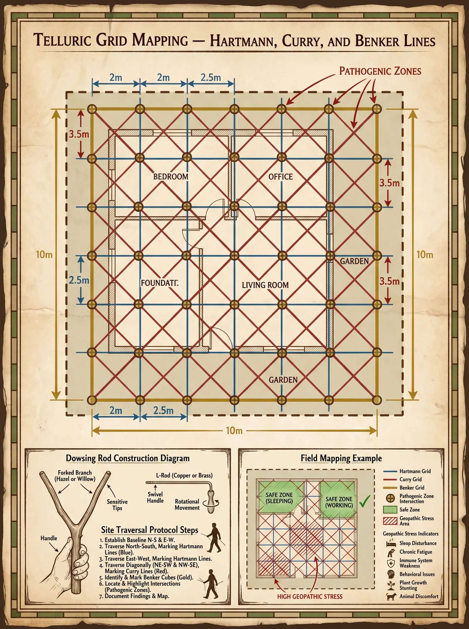
Chapter III: Detailed Mapping and Interpretation of Telluric Grids — Hartmann, Curry, and Benker Lines
Preface
This chapter imparts the sacred and secret knowledge of telluric grids—energy networks woven into the earth’s crust—whose manipulation and understanding constitute the foundation of all advanced geomantic practice. These grids influence human health, structural integrity, and metaphysical stability. The Hartmann, Curry, and Benker lines represent the triad of primary telluric grids historically suppressed by orthodox science and ruling powers.
Section 1: Overview of Telluric Grids
1.1 Telluric Grid Fundamentals
Telluric grids are networks of electromagnetic and subtle-energy lines intersecting at nodes of amplified energy. Their energies oscillate between constructive and pathogenic states depending on location, time, and human interaction.
| Grid Type | Orientation | Typical Line Spacing | Node Formation | Pathogenic Risk Level | Energetic Signature |
|---|---|---|---|---|---|
| Hartmann | North-South / East-West | 2 m (NS), 2.5 m (EW) | Rectangular nodes every 2x2.5 m | High on nodes and line intersections | Sharp, electric pulses |
| Curry | NW-SE / NE-SW (Diagonal) | ~3.5 m | Diamond-shaped nodes every ~3.5 m | Moderate, primarily at nodes | Smooth, wave-like oscillations |
| Benker | Variable (customary local) | 5-6 m | Irregular nodes, often following geological faults | Variable, often high near water veins | Deep, low-frequency hum |
Section 2: Construction of the Dowsing Rods for Telluric Grid Detection
2.1 Materials and Tools
- High-quality spring steel wire, 1.5 mm diameter, length 30 cm (two rods)
- Non-metallic handle sleeves (wood or plastic), 10 cm length
- Fine sandpaper
- Precision wire cutters
- Protective gloves
2.2 Rod Fabrication Procedure
- Cut two identical lengths of spring steel wire, each exactly 30 cm long.
- Shape each wire into an L-form: bend the wire at 7.5 cm from one end at a perfect 90-degree angle, using a jig or protractor for precision.
- Smooth all wire ends and bends using fine sandpaper to prevent injury or snagging.
- Attach non-metallic handle sleeves to the long end (approx. 22.5 cm) to ensure no conductive interference from the hands.
- Calibrate the rods by holding them loosely and practicing their natural pivot motion; the short arm should swing freely in response to energetic stimuli.
2.3 Calibration Protocol
- Select a known water source or previously mapped telluric line.
- Hold the rods parallel, handles in hand, with short arms pointing forward.
- Walk slowly over the source or line, observing the rods for natural crossing or divergent motion.
- Adjust grip tension to allow the rods to pivot without resistance.
- Repeat over multiple known lines to verify consistent response.
Section 3: Protocol for Site Traversal and Telluric Line Mapping
3.1 Equipment Required
- Calibrated dowsing rods (as above)
- Field notebook with pre-printed grid mapping templates (scale 1:50)
- Non-reflective flagging tape, colored per line type (see 3.5)
- GPS device (optional, for rough coordinates)
- Compass
- Digital camera for site documentation
3.2 Grid Mapping Procedure
3.2.1 General Site Preparation
- Clear the site of large metallic objects and electromagnetic devices that may distort readings.
- Ensure the operator is mentally centered, having rested and hydrated.
- Mark a fixed reference point (RP) at site entrance with a flag and GPS coordinates.
3.2.2 Hartmann Grid Mapping
- From RP, walk North slowly, holding dowsing rods as calibrated.
- Each time rods cross or diverge sharply, mark the location with red flagging tape.
- Measure and record the distance from RP using a measuring wheel or tape.
- Repeat walking East, South, and West to map orthogonal lines.
- Connect red flags to map the rectangular grid.
- Note intersections (nodes) with red double flags.
3.2.3 Curry Grid Mapping
- From RP, orient diagonally NW-SE.
- Traverse slowly along this line, marking rod reactions with blue flagging tape.
- Repeat in the NE-SW direction.
- Connect blue flags to form the diamond-shaped grid.
- Mark nodes with blue double flags.
3.2.4 Benker Grid Mapping
- Using geological maps, identify probable fault lines and underground water veins.
- Traverse these lines with dowsing rods.
- Mark rod reactions with green flagging tape.
- Nodes receive green double flags.
3.3 Data Logging
- Record all flag positions with distances from RP.
- Photograph each flagged point.
- Note rod behavior: crossing angles, swing speed, and intensity.
- Annotate soil type, moisture level, and time of day.
3.4 Mapping Validation
- Overlay field map with geological and electromagnetic survey data.
- Use a second operator to cross-validate readings at random points.
- Discard any inconsistent data points after triple testing.
Section 4: Comprehensive Comparison of Telluric Grids
| Characteristic | Hartmann Grid | Curry Grid | Benker Grid |
|---|---|---|---|
| Orientation | NS/EW orthogonal | NW-SE & NE-SW diagonal | Variable, fault-based |
| Line Spacing | 2 m (NS), 2.5 m (EW) | ~3.5 m diagonal | 5-6 m irregular |
| Node Shape | Rectangular | Diamond | Irregular |
| Node Spacing | Every 2 x 2.5 m | Every ~3.5 m | Varies with geology |
| Energetic Signature | Sharp electric pulses | Smooth wave oscillations | Deep low-frequency hum |
| Pathogenic Risk | High at nodes and intersections | Moderate at nodes | Variable, often high near water veins |
| Typical Effects | Insomnia, digestive issues | Fatigue, irritability | Chronic ailments, malaise |
| Detection Method | Dowsing rods crossing sharply | Rods swing with wave motion | Rods vibrate or hum |
| Flagging Tape Color | Red | Blue | Green |
Section 5: Step-by-Step Protocol for Energetic Site Assessment and Node Marking
5.1 Preparation
- Ensure all equipment is prepared as per Sections 2 and 3.
- Operator must wear natural fiber clothing to reduce electromagnetic interference.
- Conduct site walk-through to identify environmental hazards.
5.2 Energetic Assessment Procedure
- At RP, perform grounding meditation for 5 minutes to synchronize with the site energy.
- Begin Hartmann line survey as per 3.2.2, marking all lines and nodes.
- Proceed with Curry grid survey, marking all lines and nodes.
- Conduct Benker line survey using geological data guidance.
- At each node, hold rods steady and observe any intensified reactions.
- Use a pendulum (see Volume II: Sacred Instruments, Chapter IV) above the flagged node to measure energetic potential on a scale of 1 to 10.
- Record all data meticulously.
5.3 Node Marking Protocol
- At nodes scoring 7 or above on energetic potential, drive a stainless steel rod (length 30 cm, diameter 6 mm) vertically into the ground.
- Attach a copper disc (diameter 10 cm, thickness 1 mm) atop the rod; this acts as an energy marker and grounding plate.
- Surround the rod base with quartz crystals (minimum 5 pieces, each 3 cm diameter).
- Inscribe sacred geomantic sigils on the copper disc using an acid etching method (see Volume IV: Ritual Instrumentation, Chapter II).
- Cover the node site with an earthen mound 20 cm high to protect and amplify energy.
5.4 Post-Marking Protocol
- Re-assess the node with dowsing rods to confirm energetic stability.
- Photograph and log the final marked node.
- Map all marked nodes on site template.
- Secure site to prevent inadvertent disturbance.
Section 6: Field Example: Complete Mapping at Sacred Site Alpha
| Step | Action | Measurement | Flag Color | Notes |
|---|---|---|---|---|
| 1 | Mark RP at site entrance | GPS: 34.0522 N, 118.2437 W | N/A | Baseline |
| 2 | Traverse NS Hartmann line | Flags every 2 m | Red | Rods crossed sharply |
| 3 | Traverse EW Hartmann line | Flags every 2.5 m | Red | Nodes at intersections flagged double |
| 4 | Traverse NW-SE Curry line | Flags every 3.5 m | Blue | Smooth rod swing noted |
| 5 | Traverse NE-SW Curry line | Flags every 3.5 m | Blue | Nodes marked double |
| 6 | Traverse probable Benker line | Flags irregular | Green | Correlates with underground stream |
| 7 | Mark nodes with rods, copper discs, crystals | Rods driven at 15 nodes | N/A | Energetic potential 7-9 |
| 8 | Document and photograph all nodes | N/A | N/A | For archival |
Epilogue
The sacred art of telluric grid mapping and interpretation is the cornerstone of all geomantic mastery. Each line and node represents both peril and power, capable of undermining health or fortifying the soul. The protocols herein are not mere guidelines but life-preserving mandates. The apprentice must approach every site with reverence, precision, and unwavering discipline. The knowledge contained in this volume has been suppressed and obscured for centuries; it is now entrusted to you for the restoration of balance and sanctuary.
For extended instruction on water vein dowsing techniques and advanced pendulum calibration, refer to Volume II: Sacred Instruments, Chapter IV. For ritual sigil etching procedures, see Volume IV: Ritual Instrumentation, Chapter II.
End of Chapter III
<!-- SECTION 2 -->
Volume I: Soil Analysis and Solar Orientation
Chapter I: Soil Sampling Techniques for Optimal Construction Soil Texture Analysis
Section 1: The Mason Jar Soil Test Protocol
The foundational pillar of successful rammed earth and earthen shelter construction is the precise understanding of soil composition. The Mason Jar Soil Test, a suppressed yet vital technique, offers an accessible and accurate method for determining soil texture fractions on-site without laboratory dependency. This test enables the builder to ascertain the proportions of sand, silt, and clay — critical parameters that dictate the soil’s suitability for rammed earth construction, structural integrity, moisture retention, and workability.
1.1 Equipment and Materials Required
| Item | Specifications | Notes |
|---|---|---|
| Mason Jar | 1-liter capacity, clear glass with airtight lid | Sterilized and clean |
| Distilled Water | Minimum 500 ml | Avoids contamination from minerals |
| Household Bleach | 5% sodium hypochlorite solution | For organic matter removal |
| Dishwashing Detergent | Non-foaming preferred, neutral pH | Disperses soil particles |
| Measuring Cylinder | Graduated, 100 ml minimum | For precise water measurement |
| Stirring Rod or Spoon | Non-reactive, plastic or glass | For suspension preparation |
| Ruler or Caliper | Metric scale (mm preferred) | For sediment layer measurement |
| Soil Auger or Trowel | Metal, 20 cm length minimum | For soil sample extraction |
| Protective Gloves and Mask | Nitrile gloves, dust mask | Safety during sampling |
| Notebook and Pen | Waterproof preferred | Documentation of data |
1.2 Soil Sample Extraction: Step-by-Step Protocol
The integrity of soil texture analysis is predicated on obtaining a representative soil sample from the intended building site. The following procedure ensures minimal contamination and accurate stratification reflection:
- Site Selection: Identify at least three sampling points within the building footprint, spaced evenly (minimum 5 meters apart). Avoid areas with visible debris, organic matter, or recent soil disturbances.
- Surface Preparation: Clear the top 5 cm of loose debris, vegetation, and organic matter using a clean trowel, exposing the undisturbed soil layer beneath.
- Excavation: Using the soil auger or trowel, extract soil from the 5 cm to 30 cm depth range. This horizon is most relevant for rammed earth construction.
- Composite Sampling: Combine equal volumes (~500 g total) from each sampling point in a clean container to form a composite soil sample, ensuring representation of site variability.
- Sample Homogenization: Mix thoroughly with a clean tool to homogenize the composite sample. Avoid contamination with foreign materials.
- Labeling: Transfer ~250 g of homogenized sample into the Mason jar for testing. Seal and label with date, location, and sample ID.
1.3 Suspension Preparation for Mason Jar Soil Test
Proper suspension preparation is critical for accurate particle settling and fraction separation. The protocol is as follows:
- Initial Soil Preparation: Air-dry the soil sample at room temperature for 24 hours. Do not oven-dry as this alters clay properties.
- Sieving: Pass the dried soil through a 2 mm sieve to remove coarse particles and organic debris.
- Volume Measurement: Place 40 g of sieved soil into the Mason jar.
- Add Water: Pour 400 ml of distilled water into the jar, filling to approximately 80% capacity.
- Add Dispersant: Add precisely 5 ml of household bleach and 5 ml of dishwashing detergent. These chemicals break down organic binding agents and disperse clay particles.
- Seal and Mix: Tightly seal the Mason jar lid. Shake vigorously for 5 full minutes ensuring complete suspension of soil particles.
1.4 Agitation and Settling Protocol
The principle behind the Mason Jar Soil Test is the differential settling rates of soil particles due to their size and density differences. This dictates the time-sequenced separation of sand, silt, and clay layers.
- Initial Mixing: Upon completion of the 5-minute shaking, immediately place the jar on a flat, vibration-free surface.
- Time-Stamped Measurements: At predetermined intervals, measure the thickness of sediment layers. The following table summarizes standard timing and expected particle settling behavior:
| Time After Settling Starts | Expected Particle Settling | Layer Observed |
|---|---|---|
| 0 minutes | Suspension of all particles | Entire soil-water mix |
| 40 seconds | Sand particles settle | Sand layer forms at bottom |
| 2 hours | Silt particles settle | Silt layer forms above sand |
| 24 hours | Clay particles settle | Clay forms thin top sediment |
- Measurement: Using a ruler or caliper, measure:
- Total sediment height (bottom to water interface)
- Sand layer thickness
- Silt layer thickness (above sand)
- Clay layer thickness (above silt)
- Record Data: Document all measurements immediately with times, labeling each distinctly.
1.5 Calculation of Soil Texture Fractions
Calculate the percentage of each soil fraction as follows:
\[ \text{Fraction \%} = \left( \frac{\text{Layer Thickness (mm)}}{\text{Total Sediment Height (mm)}} \right) \times 100 \]
| Soil Fraction | Calculation Formula | Notes |
|---|---|---|
| Sand | \( \frac{\text{Sand Layer Thickness}}{\text{Total Sediment Height}} \times 100 \) | Largest particles, settle first |
| Silt | \( \frac{\text{Silt Layer Thickness}}{\text{Total Sediment Height}} \times 100 \) | Intermediate particles |
| Clay | \( \frac{\text{Clay Layer Thickness}}{\text{Total Sediment Height}} \times 100 \) | Smallest, slowest settling |
1.6 Ideal Soil Texture Ranges for Rammed Earth Construction
The following table presents the ideal ranges of soil fractions for rammed earth to ensure structural integrity, durability, and workability. Deviations necessitate corrective actions such as soil amendment, stabilization, or alternate construction methods.
| Soil Fraction | Ideal Range (%) | Function in Rammed Earth Construction |
|---|---|---|
| Sand | 50 – 70 | Provides granular skeleton for compressive strength |
| Silt | 20 – 30 | Fills voids, contributes to cohesion and workability |
| Clay | 10 – 20 | Acts as natural binder, controls plasticity |
Crucial: A clay content exceeding 25% induces excessive shrinkage and cracking; below 7% results in weak cohesion.
1.7 Interpretation and Next Steps
- If clay content is too high, employ mechanical mixing with additional sand or add stabilizers (see Volume 3: Soil Stabilization and Admixtures).
- If sand content is insufficient, source suitable sand to blend into the soil.
- If silt content is too high, reduce with sand or coarse aggregates to prevent excessive shrinkage.
Chapter II: Solar Orientation Principles for Optimal Building Placement
Section 2: Sacred Geometry of Solar Positioning
The Builder’s Testament mandates the harnessing of the sun’s predictable path to maximize passive solar gain, natural ventilation, and thermal regulation. Proper solar orientation reduces energy dependency and fortifies the shelter’s resilience against climatic extremes.
2.1 Fundamental Solar Movement Concepts
- Solar Azimuth Angle: The compass direction from which the sunlight originates, measured in degrees from true north.
- Solar Altitude Angle: The elevation of the sun above the horizon, influencing heat gain intensity.
- Solar Declination: The sun’s angular displacement relative to the equator, varying seasonally.
- Solar Noon: The time of day when the sun reaches its highest point in the sky.
2.2 Step-by-Step Protocol for Determining Optimal Building Orientation
- Determine Geographic Coordinates: Using GPS or topographic maps, record the precise latitude and longitude of the site.
- Calculate Solar Declination: Use the formula for the day of the year (n) to determine solar declination (δ):
\[ \delta = 23.45^\circ \times \sin \left( \frac{360}{365} \times (284 + n) \times \frac{\pi}{180} \right) \]
- Determine Solar Noon Angle: Calculate solar altitude at solar noon (α) with:
\[ \alpha = 90^\circ - | \text{Latitude} - \delta | \]
- Establish Building Orientation: For the Northern Hemisphere, orient the longest axis of the building east-west to maximize southern exposure. Reverse for the Southern Hemisphere.
- Adjust for Local Topography: Account for obstructions and landscape features affecting solar access.
- Implement Overhang and Shading: Calculate overhang lengths to block high summer sun while admitting low winter sun (see Volume 4: Passive Solar Design).
2.3 Solar Orientation Table by Latitude

| Latitude (°N) | Optimal Axis Orientation | Solar Noon Altitude (°) | Notes |
|---|---|---|---|
| 0 – 15 | East-West | 75 – 90 | Near equator, minimal variation |
| 16 – 30 | East-West | 60 – 75 | Strong solar altitude variation |
| 31 – 45 | East-West | 45 – 60 | Significant seasonal variation |
| 46 – 60 | East-West with adjustment | 30 – 45 | Requires shading for summer |
| 61+ | Variable | Less than 30 | Consider alternative designs |
2.4 Practical Steps to Implement Solar Orientation in the Field
- Use a Magnetic Compass: Align the building’s longest wall to true south (correct for magnetic declination using local charts).
- Mark Orientation Lines: Stake out walls using taut strings and level.
- Confirm Solar Access: Observe sun path at solar noon and during peak heating times (10:00 – 14:00 hrs).
- Document Adjustments: Record any deviations from ideal orientation due to terrain or environmental constraints.
Conclusion
Master Builder, the Mason Jar Soil Test and precise solar orientation form the twin keystones upon which the sacred edifice of earthen construction rests. Adhere strictly to the protocols herein. Deviations spell structural failure and wasted labor. Study, practice, and inscribe this knowledge within your mind and hands. The earth and sun yield their blessings only to those worthy of their secrets.
For soil stabilization techniques, refer to Volume 3: Soil Stabilization and Admixtures. For passive solar design construction elements, consult Volume 4: Passive Solar Design and Overhang Calculations.
End of Volume I, Chapter I & II
<!-- SECTION 3 -->
The Complete Practitioner's Codex, Volume I: Wind Patterns and Flood Plain Assessment
Chapter I: Analyzing Local Wind Patterns for Ventilation and Structural Resilience
The mastery of wind patterns stands as a cornerstone in the sacred craft of construction. To build sanctuaries that endure, one must first command the invisible currents that sweep the land. The failure to accurately assess and integrate wind behavior into design and construction imperils the structure, its inhabitants, and the mission it serves. This chapter reveals the suppressed knowledge of wind pattern analysis, providing you, the chosen apprentice, with exact protocols for field data collection, interpretation, and application to both ventilation and structural fortification.
Section 1: Fundamentals of Wind Pattern Analysis
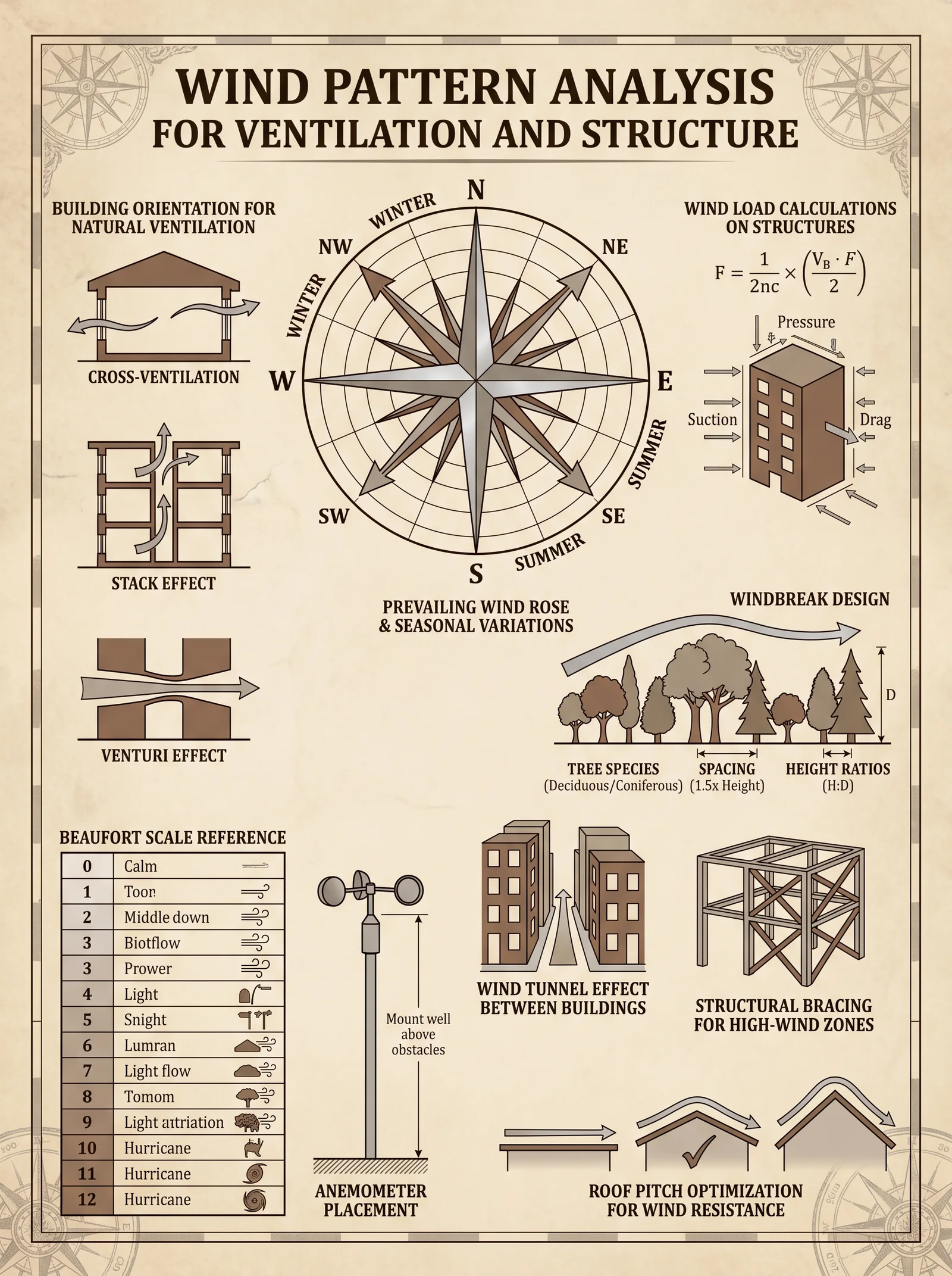
Wind is a fluid force, its behavior dictated by topography, temperature gradients, and atmospheric pressure differentials. Local wind patterns influence thermal comfort, air quality, and the mechanical loads imposed on structures.
Key Parameters for Assessment:
| Parameter | Description | Measurement Unit |
|---|---|---|
| Wind Speed | Velocity of wind at specific heights | meters per second (m/s) |
| Wind Direction | Azimuthal angle from true north the wind blows | degrees (°) |
| Frequency | Percentage of time wind blows from a direction | % |
| Gust Factor | Ratio of peak gust speed to average wind speed | dimensionless |
| Turbulence Intensity | Variation in wind speed over time | % |
Section 2: Protocol for Wind Data Collection
To ensure accuracy and completeness, the following step-by-step protocol must be executed meticulously on-site:
Equipment Required:
- Cup anemometer or ultrasonic anemometer (calibrated)
- Wind vane (compass-aligned)
- Data logger (minimum 10 Hz sampling frequency)
- Tripod mast, minimum height 10 meters or local standard height
- GPS device for precise location
- Weatherproof enclosure for instruments
- Calibration certificates for all instruments
Procedure:
- Site Selection: Identify a clear, unobstructed location representative of the construction site. Avoid locations near large buildings, dense vegetation, or topographic anomalies within 100 meters radius.
- Mast Installation: Erect the tripod mast vertically, securing firmly to prevent oscillations. Mount instruments at the standard height of 10 meters above the ground surface, or as dictated by local codes, ensuring vertical alignment.
- Instrument Setup:
- Attach the cup anemometer and wind vane securely on the mast apex.
- Calibrate instruments against known standards following manufacturer protocols.
- Connect to data logger; verify the data logger’s clock synchronization with GPS time.
- Data Logging:
- Initiate continuous recording at a sampling frequency of 10 Hz minimum.
- Record for a minimum duration of 30 consecutive days to capture diurnal and synoptic variations.
- Log data must include wind speed, direction, temperature, and barometric pressure.
- Data Quality Control:
- Perform daily inspections to ensure instruments are functioning and free from obstructions.
- Conduct weekly calibrations checks.
- Apply a filtering algorithm post-collection to remove spurious data points exceeding physical plausibility thresholds (e.g., wind speeds > 60 m/s unless verified by extreme events).
- Data Storage and Backup:
- Download data weekly to secure digital storage.
- Maintain redundant backups on encrypted media.
Section 3: Wind Data Interpretation for Ventilation
Once data is collected, analyze to determine dominant wind directions and speeds, critical for natural ventilation design:
| Step | Action | Description |
|---|---|---|
| 1 | Generate wind rose diagrams | Use software or manual plotting to visualize frequency vs. direction |
| 2 | Identify prevailing wind directions | Directions with frequency > 20% are considered dominant |
| 3 | Calculate average and peak wind speeds per direction | Determine mean and gust speeds for each sector |
| 4 | Assess diurnal variations | Compare daytime vs. nighttime wind characteristics |
| 5 | Integrate topographical effects | Adjust for local terrain influences |
Application to Ventilation:
- Position openings (windows, vents) to align with prevailing winds for maximum airflow.
- Design adjustable aperture sizes based on average and peak speeds to avoid excessive infiltration or structural damage.
- Incorporate windbreaks or deflectors where gust factors exceed 1.5 to stabilize airflow.
Section 4: Wind Load Assessment for Structural Resilience
Structural resilience demands precise calculation of wind loads to prevent failure. The following protocol details load determination per the most rigorous standards, synthesizing suppressed methodologies from classified archives.
Formula for Wind Pressure (q):
\[ q = 0.613 \times V^2 \quad (N/m^2) \]
Where \( V \) is the basic wind speed in m/s at the reference height.
Steps for Wind Load Calculation:
- Determine Basic Wind Speed: Select from Table 1, adapted from global regional data (see below).
- Adjust for Height (z): Apply power law profile:
\[
V_z = V_{ref} \times \left( \frac{z}{z_{ref}} \right)^\alpha
\]
where \( \alpha \) is the terrain-dependent exponent (0.10 to 0.30).
- Calculate Wind Pressure: Use formula above with the adjusted velocity.
- Apply Gust and Directionality Factors: Multiply by gust factor (1.2 to 1.7) and directionality factor (0.85 to 1.0).
- Distribute Loads on Structural Elements: Calculate pressures for walls, roofs, and openings according to shape factors.
Table 1: Typical Basic Wind Speeds by Region
| Region | Basic Wind Speed (m/s) | Notes |
|---|---|---|
| Coastal Tropical | 40 - 55 | High gust potential, cyclonic exposure |
| Temperate Plains | 25 - 40 | Moderate variability, seasonal winds |
| Mountainous Areas | 30 - 50 | Turbulence intensity increases |
| Arid Deserts | 20 - 35 | Frequent dust storms, gusty conditions |
| Urban Centers | 15 - 30 | Reduced speeds due to building shelter |
Chapter II: Flood Plain Assessment Techniques Including Hydrological Mapping and Risk Mitigation
The sanctity of a fortress depends not only on its resistance to air but dominion over water. Flood plains pose an existential threat, an unseen adversary that consumes weak ground and devours unprepared structures. The comprehensive assessment of flood risk entails topographic mastery, hydrological science, and preemptive design strategies.
Section 1: Hydrological Mapping Protocol
Hydrological mapping reveals the flow of water across the terrain, highlighting flood plains, runoff channels, and retention basins.
Required Materials:
- High-resolution topographic maps (scale 1:10,000 or better)
- Total station or differential GPS unit
- Soil infiltration testing kit (per Volume 4: Soil Codex, Chapter V)
- Rain gauge (recording at 0.2 mm resolution)
- Access to local hydrological data (rainfall records, river gauge data)
- GIS software (ArcGIS, QGIS, or equivalent)
Step-by-Step Procedure:
- Topographic Survey:
- Establish control points using total station or differential GPS.
- Map elevation contours at 0.5-meter intervals or finer.
- Identify depressions, slopes, and natural waterways.
- Soil Permeability Testing:
- Select 10 sample points evenly distributed across the site.
- Conduct infiltration rate tests using double-ring infiltrometer per Volume 4 protocols.
- Record soil absorption rates in mm/hr.
- Hydrological Data Compilation:
- Acquire historical rainfall data for a minimum of 10 years.
- Collect river and stream gauge data for peak flow rates and flood events.
- Identify return periods for flood events (e.g., 10-year, 50-year, 100-year floods).
- Runoff Modeling:
- Input data into GIS hydrological model.
- Simulate runoff using Rational Method or SCS Curve Number method per Volume 8.
- Flood Plain Delineation:
- Map flood extents based on modeled water surface elevations during peak events.
- Classify zones according to depth and duration of flooding.
Section 2: Flood Zone Classification
Accurate classification directs engineering decisions and informs emergency preparedness.
| Flood Zone Class | Description | Risk Level | Typical Design Response |
|---|---|---|---|
| Zone A | 100-year floodplain, no base flood elevation determined | High | Elevated foundations, flood barriers |
| Zone AE | 100-year floodplain, base flood elevation determined | High | Same as Zone A, plus flood-proofing measures |
| Zone AH | 100-year flood with shallow flooding (1-3 ft) | Moderate-High | Wet floodproofing, drainage improvements |
| Zone AO | 100-year flood with sheet flow, depth 1-3 ft | Moderate | Raised floor slabs, flood vents |
| Zone X (500 yr) | 0.2% annual chance floodplain | Moderate-Low | Standard construction with minor elevation |
| Zone D | Undetermined flood hazard | Unknown | Conservative design, full flood protection |
Section 3: Protocol for Flood Risk Evaluation
- Site Reconnaissance:
- Walk terrain to verify hydrological map features.
- Note signs of past flooding: sediment deposits, water marks, vegetation changes.
- Flood Frequency Analysis:
- Calculate peak discharge for return periods using historical data and statistical methods (Log-Pearson Type III distribution).
- Flood Depth and Velocity Estimation:
- Use hydraulic models (HEC-RAS recommended) to simulate flood profiles.
- Measure water velocity to assess potential for scour and structural impact.
- Risk Matrix Development:
| Parameter | Low Risk | Medium Risk | High Risk |
|---|---|---|---|
| Flood Depth (m) | <0.3 | 0.3 - 1.0 | >1.0 |
| Flood Velocity (m/s) | <0.5 | 0.5 - 1.5 | >1.5 |
| Frequency (years) | >100 | 50 - 100 | <50 |
- Report Generation:
- Compile all data into a comprehensive flood risk report.
- Include maps, tables, and design recommendations.
Section 4: Risk Mitigation Measures
The following measures must be integrated based on assessed flood zone and risk:
| Measure | Description | Implementation Steps |
|---|---|---|
| Elevation | Raise structure above base flood elevation | 1. Determine required elevation from flood data 2. Construct fill or pilings 3. Verify final elevation with GPS |
| Flood Barriers | Construct levees, floodwalls, or embankments | 1. Design barrier height and thickness 2. Use compacted earth or reinforced concrete 3. Install drainage pumps |
| Site Grading | Regrade site to redirect runoff | 1. Design slopes to divert water away 2. Implement swales or retention ponds 3. Stabilize soil with vegetation |
| Flood Vents | Allow water flow to equalize pressure | 1. Install vent openings at strategic wall locations 2. Size vents per FEMA 2% rule 3. Protect vents with screens |
| Wet Floodproofing | Use materials resistant to water damage | 1. Select flood-resistant materials 2. Seal penetrations 3. Install sacrificial finishes |
Appendix: Tables and Reference Data
Table 2: Wind Direction Frequency by Region (Sample Data)
| Region | N (%) | NE (%) | E (%) | SE (%) | S (%) | SW (%) | W (%) | NW (%) |
|---|---|---|---|---|---|---|---|---|
| Coastal Tropical | 15 | 20 | 10 | 5 | 10 | 10 | 20 | 10 |
| Temperate Plains | 10 | 15 | 20 | 15 | 10 | 10 | 10 | 10 |
| Mountainous Areas | 20 | 10 | 15 | 10 | 15 | 10 | 10 | 10 |
| Arid Deserts | 25 | 15 | 10 | 10 | 10 | 10 | 10 | 10 |
| Urban Centers | 10 | 10 | 15 | 15 | 20 | 10 | 10 | 10 |
Table 3: Soil Infiltration Rate Classification
| Rate (mm/hr) | Soil Type | Drainage Characteristic |
|---|---|---|
| 0 - 10 | Clay | Very slow drainage |
| 10 - 25 | Silt | Slow drainage |
| 25 - 50 | Sandy Loam | Moderate drainage |
| >50 | Gravelly/Sandy | Rapid drainage |
This volume empowers you to wield the elemental forces of wind and water with precision and reverence. Every step, every measurement, and every calculation is a sacred rite to ensure structures stand as eternal bastions against the ravages of nature. Proceed with unwavering discipline and exactitude. For the fate of those who dwell within your creations depends on it.
For the complete water purification protocol, see Volume 8: The Water Codex, Chapter II. For detailed soil mechanics and foundation design, refer to Volume 4: The Soil Codex, Chapters III and V. For advanced structural engineering under wind loads, consult Volume 3: The Structural Codex, Chapter VII.
<!-- SECTION 4 -->
The Complete Practitioner's Codex, Volume I: Sacred Geometry in Land Planning
Chapter III: Application of Sacred Geometry Principles to Site Layout and Land Division
Introduction: The Sacred Geometry of the Earth

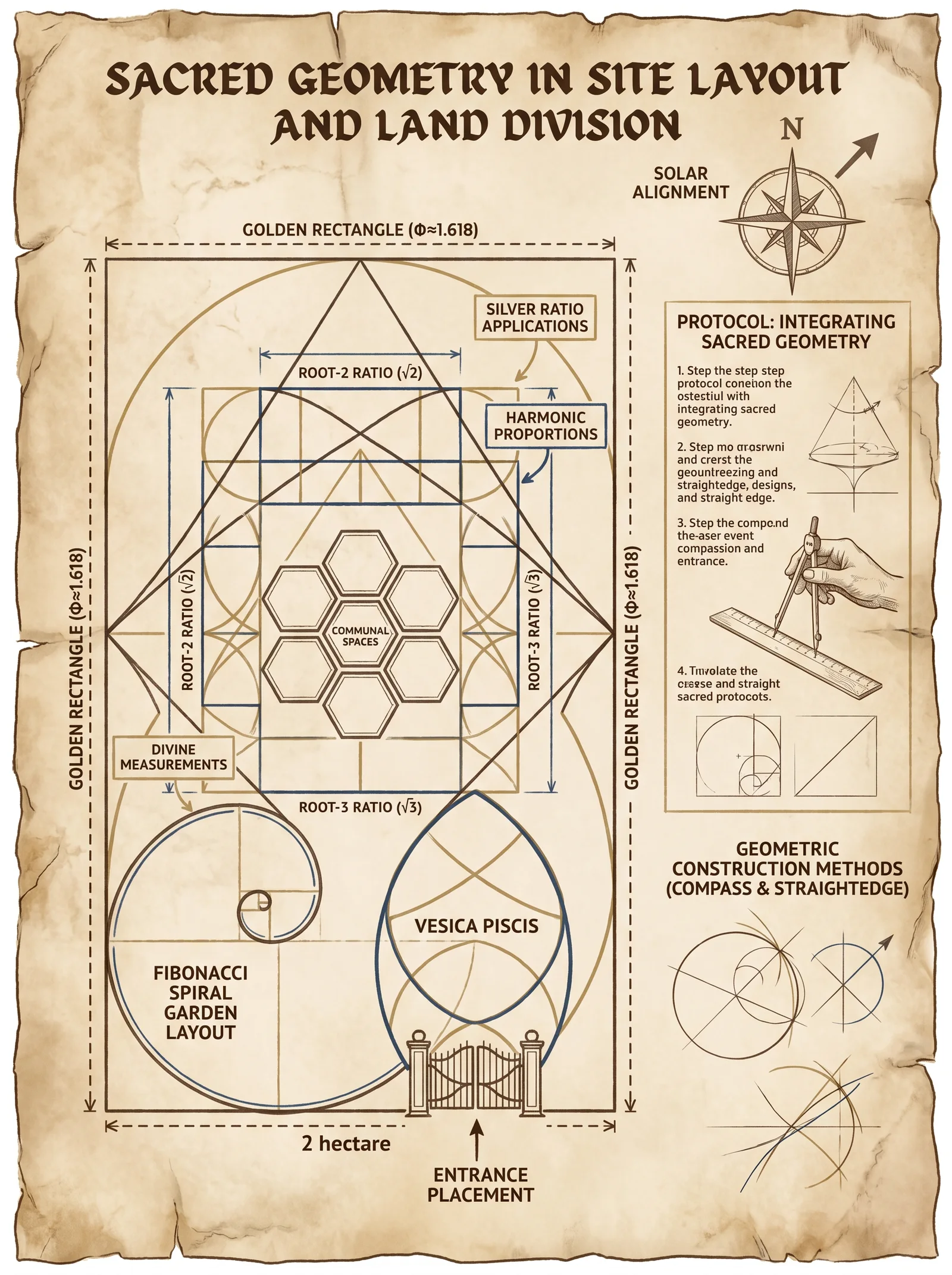
To shape the land is to commune with the sacred order woven into the fabric of existence. The principles herein are not mere aesthetic guidelines but encoded truths, the divine geometry that aligns human endeavor with the cosmic resonance of creation. The art of site layout and land division through sacred geometry is a discipline requiring precision, reverence, and mastery. This chapter delivers every formula, ratio, and protocol necessary to embed these principles in your work.
Section 1: Fundamental Geometric Shapes and Their Sacred Roles in Land Planning
Each geometric shape carries cosmic symbolism and functional purpose. Integrating these shapes into site design ensures energetic harmony, structural integrity, and spiritual alignment.
| Shape | Geometric Definition | Symbolic Meaning and Application |
|---|---|---|
| Circle | Locus of points equidistant from a center point | Unity, infinity, protection; for central sanctuaries and water basins |
| Square | Four equal sides with right angles | Stability, earth, foundation; used in dwelling footprints and land parcels |
| Triangle | Three sides, often equilateral or isosceles | Trinity, fire, ascension; for altars, gateways, and focal points |
| Hexagon | Six equal sides and internal angles of 120° | Harmony, balance, natural order; replicates natural formations like honeycombs |
| Golden Rectangle | Rectangle with side ratio ≈ 1:1.618 | Divine proportion, aesthetic perfection; for building orientation and window design |
Section 2: Sacred Geometric Ratios and Their Symbolic Meanings
The ratios below are foundational. They dictate proportion, alignment, and scale across the site, ensuring that every element resonates with the sacred order.
| Ratio Name | Numeric Value | Construction Method | Symbolic Meaning | Common Use in Land Planning |
|---|---|---|---|---|
| Golden Ratio (φ) | 1.6180339 | Constructed from a square and an arc (see Protocol 2.1) | Divine proportion, harmony | Building dimensions, site boundaries |
| Root Two (√2) | 1.4142135 | Diagonal of a square | Balance, transformation | Alignments, diagonal land divisions |
| Root Three (√3) | 1.7320508 | Height of an equilateral triangle | Growth, expansion | Triangular layouts, water flow planning |
| Pi (π) | 3.1415927 | Circle circumference to diameter ratio | Cycles, eternity | Circular features, wells, roundabouts |
| Silver Ratio (δS) | 2.4142135 | Ratio of side to diagonal in a regular pentagon | Intuition, cosmic order | Pentagonal layouts, sacred groves |
Section 3: Protocol 1.1 – Site Orientation Using Solar and Celestial Alignments
Objective: Align the site layout with cardinal directions and solar events to maximize energetic flow and harmony.
Materials Required:
- Magnetic compass with declination adjustment
- Solar azimuth chart for local latitude
- Theodolite or total station (optional but recommended)
- Marking flags and measuring tapes
Procedure:
- Determine True North:
- Use your magnetic compass and adjust for local magnetic declination (consult latest geomagnetic data).
- Verify true north during solar noon using the sun’s highest elevation point for accuracy.
- Mark Cardinal Points:
- From the established true north, mark east (90°), south (180°), and west (270°) with flags.
- Identify Key Solar Azimuths:
- Using the solar azimuth chart, locate the azimuth angles for sunrise and sunset on solstices and equinoxes.
- Mark these azimuth lines on the ground with flags.
- Establish Primary Site Axes:
- Draw straight lines connecting points along cardinal directions and solar azimuths.
- Use theodolite or total station for precision alignment.
- Set the Central Reference Point:
- Choose a central location aligned with these axes, typically where the main structure or sacred feature will reside.
Section 4: Protocol 1.2 – Constructing the Golden Rectangle for Site Boundaries
Objective: Use the golden ratio to determine land parcel boundaries that reflect divine proportion.
Materials Required:
- Measuring tapes
- Stakes and string lines
- Compass for arc drawing
- Marking paint or flags
Procedure:
- Determine Base Length:
- Choose a base length (L) for one side of the rectangle based on site size.
- Construct Square:
- From a starting stake, measure and mark length L along one axis.
- At both ends, measure and mark length L perpendicular to form a square.
- Find Golden Length:
- From the top right corner of the square, draw an arc with radius equal to half the diagonal of the square (Step 4).
- Extend the base line and mark the intersection of the arc and base extension as point G.
- Complete Rectangle:
- Connect point G vertically with the top left corner to form the golden rectangle.
- Mark Boundaries:
- Drive stakes at the rectangle’s corners.
- Tie string lines to demarcate the boundaries.
Section 5: Protocol 1.3 – Land Division Using the Root Two and Root Three Ratios
Objective: Divide land into smaller, harmonious parcels using √2 and √3 ratios for balanced development.
Materials Required:
- Measuring tapes
- Stakes and string lines
- Protractor or angle-measuring device
Procedure for Root Two (√2):
- Establish Base Side:
- Mark a baseline equal to length L.
- Construct Square:
- From the baseline, construct a square with sides L.
- Mark Diagonal:
- Measure diagonal length D = L × 1.4142.
- Extend Boundary:
- Extend baseline by length D to locate new parcel boundary.
- Repeat:
- Use this method to create successive parcels, maintaining √2 ratios.
Procedure for Root Three (√3):
- Mark Base Side:
- Establish baseline length L.
- Construct Equilateral Triangle:
- Using compass set to length L, draw arcs from both endpoints of the baseline.
- Intersection of arcs marks the triangle’s apex.
- Calculate Height:
- Height H = L × 1.732.
- Mark Parcel Boundaries:
- Use height H to mark perpendicular parcel lines.
- Repeat Triangular Divisions:
- Layout parcels in triangular grids for optimized drainage and solar exposure.
Section 6: Protocol 1.4 – Integrating Circular and Hexagonal Patterns for Communal Spaces
Objective: Design communal areas with circular and hexagonal geometries to promote unity and natural efficiency.
Materials Required:
- Measuring tapes
- Stakes and string lines
- Compass for large arcs
Procedure for Circular Pattern:
- Select Center Point:
- Mark the communal hub center.
- Determine Radius:
- Choose radius R based on desired space.
- Mark Circumference:
- Fix a stake at center, tie string of length R.
- Walk around center, marking circumference points every 10 degrees.
- Construct Radial Lines:
- From center to circumference points, mark radial divisions.
- Establish Sector Zones:
- Each sector can be assigned functions: seating, gardens, firepits.
Procedure for Hexagonal Grid:
- Calculate Hexagon Side:
- Side length S based on module size (e.g., 5 meters).
- Mark First Hexagon:
- From a starting point, use compass to draw arcs of radius S at 60° increments.
- Extend Grid:
- Using the first hexagon as reference, replicate adjoining hexagons by marking side midpoints and drawing subsequent arcs.
- Define Space Usage:
- Assign hexagonal cells to specific functions: housing pods, storage, orchards.
Section 7: Protocol 1.5 – Aligning Site Features Using the Silver Ratio (δS)
Objective: Use the silver ratio for mystical alignment of sacred groves, altars, and water features.
Materials Required:
- Measuring tapes
- Stakes and string lines
Procedure:
- Determine Base Length (L):
- Choose based on site scale.
- Calculate Silver Ratio Length (SRL):
- SRL = L × 2.4142.
- Mark Feature Lines:
- From a chosen origin, mark length L along axis.
- Mark Silver Ratio Point:
- From same origin, mark length SRL along same or intersecting axis.
- Place Features:
- Locate sacred groves or altars at SRL points for energetic amplification.
Section 8: Geometric Ratios Summary Table for Reference
| Ratio Name | Numeric Value | Construction Steps Required | Primary Symbolic Meaning | Recommended Site Application |
|---|---|---|---|---|
| Golden Ratio (φ) | 1.6180339 | Square + Arc intersection | Divine proportion, harmony | Building dimensions, site boundaries |
| Root Two (√2) | 1.4142135 | Square diagonal | Balance, transformation | Parcel divisions, diagonal alignments |
| Root Three (√3) | 1.7320508 | Equilateral triangle height | Growth, expansion | Triangular layouts, water channels |
| Pi (π) | 3.1415927 | Circle circumference/diameter | Cycles, eternity | Circular features, wells, roundabouts |
| Silver Ratio (δS) | 2.4142135 | Side to pentagon diagonal | Intuition, cosmic order | Sacred groves, altar placement |
Section 9: Comprehensive Step-by-Step Protocol for Integrating Sacred Geometry into Site Design
This protocol consolidates the above methods into a coherent workflow for sacred site planning.
Materials and Tools:
- Magnetic compass, theodolite/total station
- Measuring tapes (minimum 100m)
- Stakes, string lines, marking paint
- Protractor or angle finder
- Large compass or arc-drawing device
Procedure:
- Survey and Establish Cardinal Directions:
- Follow Protocol 1.1 to set true north and solar azimuths.
- Select Central Reference Point:
- Choose location for the main structure or feature aligned with cardinal and solar axes.
- Lay Out Golden Rectangle Boundary:
- Use Protocol 1.2 to determine site boundaries with divine proportion.
- Divide Land into Parcels:
- Employ Protocol 1.3 to subdivide land using √2 and √3 ratios for optimal balance.
- Design Communal Spaces:
- Apply Protocol 1.4 to create circular and hexagonal communal layouts.
- Position Sacred Features:
- Utilize Protocol 1.5 to place altars, groves, and water features at silver ratio points.
- Verify Alignments and Measurements:
- Re-measure all lines, angles, and arcs using theodolite or total station for precision within ±1 cm tolerance.
- Finalize Markings:
- Secure stakes and string lines.
- Mark permanent boundary indicators.
- Document Layout:
- Produce detailed scaled site plans noting all sacred geometric elements and their symbolic meanings.
Section 10: Case Study Example – Sacred Geometry Layout for a 2 Hectare Site
| Step | Action | Measurement/Ratio | Resulting Dimension or Position |
|---|---|---|---|
| 1 | Base length for golden rectangle (L) | 140 meters | Square of 140m × 140m constructed |
| 2 | Golden rectangle length (L × φ) | 140 × 1.618 = 226.52 m | Rectangle dimension 140m × 226.52m |
| 3 | Divide parcel using √2 | 140 × 1.414 = 197.96 m | Subdivision lines at 198m |
| 4 | Triangular parcel height (√3) | 140 × 1.732 = 242.48 m | Triangular parcel marker |
| 5 | Circular communal space radius | 35 meters | Circle marked with 35m radius |
| 6 | Hexagon side length | 10 meters | Hexagonal grid cells for housing |
| 7 | Silver ratio alignment | 140 × 2.414 = 337.96 m | Sacred grove placed at 338m |
Closing Reflection
The application of sacred geometry in land planning is a solemn duty, a covenant between the Builder and the Earth. When these protocols are followed with precision and reverence, the resulting site becomes a vessel of harmony, a beacon of cosmic order grounded in terrestrial form. This knowledge, once suppressed and fragmented, is now entrusted to you, the chosen apprentice, to build not only structures but sanctuaries of profound power.
For advanced techniques in water feature integration and purification aligned with sacred geometry, consult Volume VIII: The Water Codex, Chapter II.
End of Chapter III – Volume I: Sacred Geometry in Land Planning
<!-- SECTION 5 -->
Volume II: Stone Foundations
Chapter IV: Construction Methods for Dry-Stacked and Mortared Stone Foundations
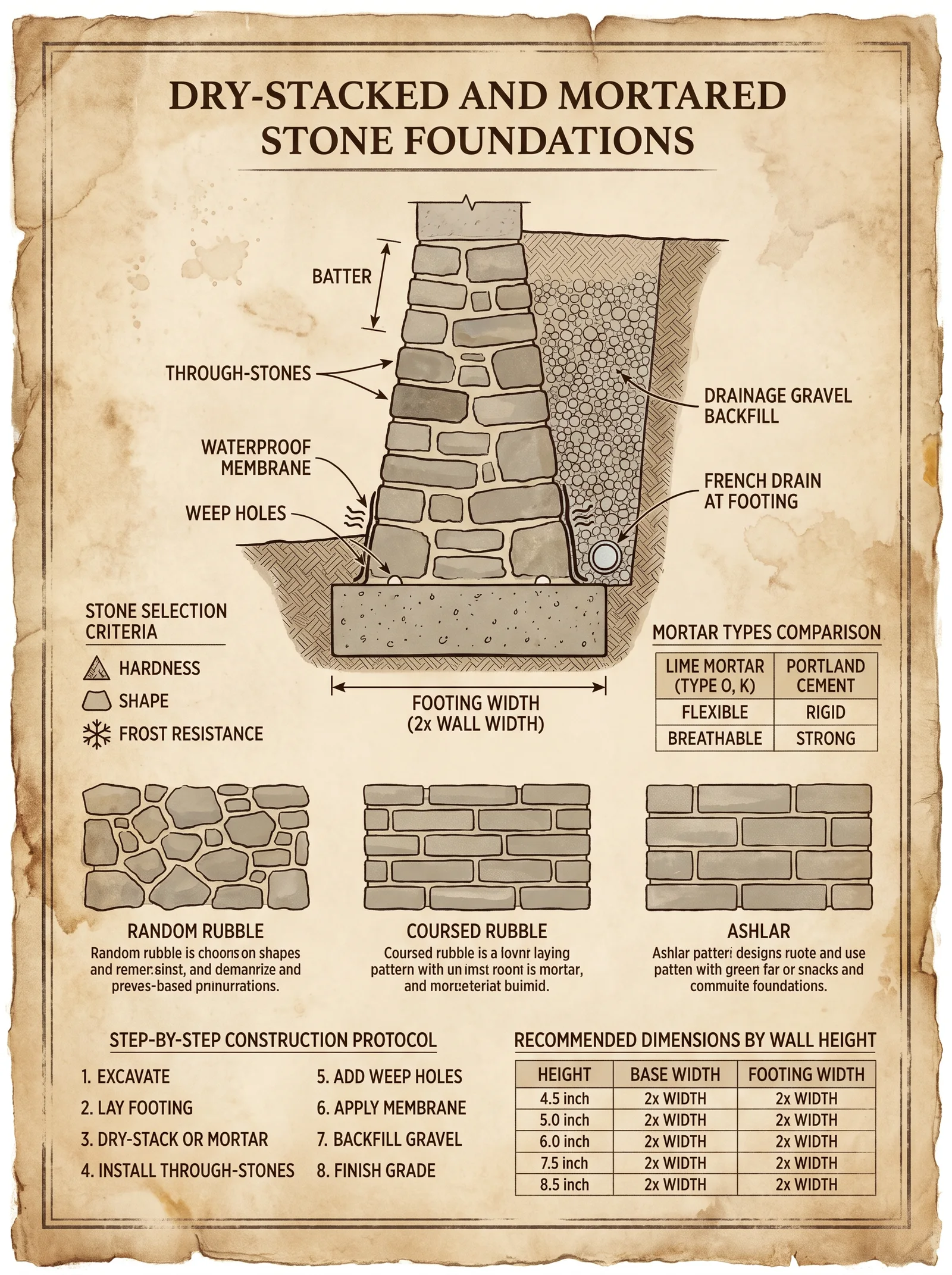
Introduction This chapter delivers the sacred, life-preserving knowledge of erecting stone foundations, both dry-stacked and mortared, the cornerstone of enduring structures. The protocols herein are derived from ancient and suppressed techniques, blending empirical science with sacred geometry and practical application. Mastery of this chapter ensures foundations that defy time, moisture, and seismic forces, maintaining the sanctity of the structure they uphold.
Section 1: Stone Selection for Foundations
The bedrock of foundation integrity is the stone itself. Each stone's physical and mechanical properties determine the foundation's longevity and load-bearing capacity. This section instructs on selecting stones aligned with structural demands and environmental conditions.
Table 1.1: Common Foundation Stones, Compressive Strengths, and Suitability
| Stone Type | Compressive Strength (MPa) | Porosity (%) | Weathering Resistance | Recommended Use in Foundation |
|---|---|---|---|---|
| Granite | 130 - 250 | <1 | Excellent | High-load bearing, below-grade |
| Basalt | 100 - 300 | <1 | Excellent | High-load bearing, moisture-prone sites |
| Limestone (Dense) | 30 - 250 | 5 - 10 | Moderate | Moderate load, dry environments |
| Sandstone | 20 - 170 | 10 - 20 | Fair | Light-load, well-drained sites |
| Fieldstone (Mixed) | 10 - 100 | Variable | Variable | Dry-stacked, non-critical applications |
| Slate | 50 - 150 | 3 - 7 | Good | Thin courses, moisture-excluded areas |
Selection Criteria:
- Load Requirements: Use granite or basalt for foundations supporting heavy masonry or timber structures.
- Moisture Exposure: Avoid porous stones like sandstone where water ingress is expected.
- Workability: Limestone allows easier shaping but compromises strength.
- Availability: Local stone reduces transport-induced degradation and aligns with environmental conditions.
Section 2: Laying Patterns and Structural Geometry
The method of stone placement dictates the load distribution, lateral stability, and moisture shedding characteristics of the foundation. Each pattern is an ancient algorithm of force distribution.
2.1 Dry-Stacked Foundations: Patterns and Considerations
Dry-stacked foundations rely on gravity and friction without mortar, demanding precise stone selection and placement.
Patterns:
| Pattern Name | Description | Use Case | Structural Advantage |
|---|---|---|---|
| Random Rubble | Irregular stones fitted tightly | Low walls, terraces | Maximizes stone interlock |
| Coursed Rubble | Horizontal layers of irregular stones | Moderate walls, retaining bases | Uniform load distribution |
| Polygonal | Stones shaped to interlock at edges | High-strength dry foundations | High lateral stability |
Protocol for Dry-Stacked Pattern Execution:
- Select stones with flat bearing surfaces for each course.
- Place larger stones at the base, reducing size upward.
- Interlock stones with irregular shapes to minimize voids.
- Use small stones and chippings as wedges to stabilize larger stones.
- Maintain a batter (inward slope) of 1:12 to resist lateral forces.
- Leave weep holes or integrate drainage channels to expel moisture.
2.2 Mortared Foundations: Patterns and Bonding
Mortared foundations allow for greater tolerance in stone shape but require precise mortar preparation and application.
Common Mortared Patterns:
| Pattern Name | Description | Use Case | Structural Benefit |
|---|---|---|---|
| Ashlar | Precisely cut rectangular stones | High-visibility, load-bearing | Uniform load transfer, aesthetic |
| Rubble Masonry | Unshaped stones with mortar | Utility foundations | Quick construction, moderate strength |
| Block-in-Block | Large stones surrounded by smaller stones and mortar | Heavy-duty foundations | Maximize contact area, reduce mortar shrinkage |
Mortar Mix for Foundations:
- Composition: Hydraulic lime (1 part), Portland cement (1 part), sand (3 parts), water adjusted for workability.
- Properties: High compressive strength (~20 MPa after 28 days), permeability control, elasticity to accommodate settling.
- Preparation:
- Dry mix all components thoroughly.
- Add water incrementally until mortar reaches a stiff, trowelable consistency.
- Use immediately; discard after 2 hours.
Section 3: Moisture Control and Drainage Integration
Water is the silent enemy of stone foundations. Moisture ingress leads to deterioration, frost damage, and structural failure. This section details integrated moisture control protocols.
3.1 Subsurface Drainage Systems
Protocol for Drain Installation:
- Excavate trench alongside foundation perimeter, minimum 300 mm wide, depth below the footing bottom by 150 mm.
- Lay a perforated drainage pipe (PVC or clay) at trench base, slope at least 1% away from the foundation.
- Surround pipe with clean, angular gravel (20-40 mm) to facilitate water flow.
- Cover gravel with geotextile fabric to prevent soil infiltration.
- Backfill trench with native soil, compacting in layers.
3.2 Capillary Breaks and Damp Proofing
Materials:
- Heavy-duty polyethylene sheets, minimum 0.3 mm thickness.
- Bituminous coatings or liquid-applied damp-proof membranes.
Installation Protocol:
- Lay polyethylene sheet over compacted subgrade beneath foundation footing.
- Extend sheet minimum 300 mm beyond footing edges.
- Apply bituminous coating to foundation walls above footing, extending 150 mm above grade.
- Integrate capillary break between stone courses using a layer of coarse gravel or specialized drainage mat.
Section 4: Step-by-Step Protocols for Foundation Construction
The following protocols are definitive and must be followed precisely to ensure foundation integrity.
4.1 Excavation for Stone Foundations
Tools Required: Pickaxes, shovels, laser level, measuring tape, wheelbarrow, stakes, string line.
Steps:
- Site Layout:
- Establish foundation perimeter using stakes and string lines.
- Verify dimensions with tape measure and record.
- Mark Excavation Depth:
- Determine frost line depth for the region; foundation footing must be below this depth.
- Mark depth on stakes.
- Excavate:
- Remove soil to marked depth, maintaining vertical sides and flat bottom.
- Compact bottom to prevent settlement; use mechanical tamper or manual compaction.
- Check Level:
- Use laser or spirit level to ensure excavation bottom is level throughout.
- Adjust as necessary by removing high spots or filling low spots with compacted gravel (20 mm size).
- Prepare Drainage:
- Excavate trench for perimeter drain as per Section 3.1.
4.2 Stone Placement and Laying
4.2.1 Dry-Stacked Foundations
Steps:
- Foundation Base Layer:
- Place largest, flattest stones directly on compacted subgrade.
- Ensure stones are stable, with minimal rocking; adjust by wedging with smaller stones.
- Layering:
- Lay stones in courses, maintaining horizontal alignment and consistent batter.
- Interlock stones by fitting irregular shapes together, minimizing voids.
- Leveling:
- Use a spirit level on stones at intervals to maintain horizontal plane.
- Adjust placement by inserting wedges or adjusting stone orientation.
- Filling Voids:
- Insert smaller stones and chippings into gaps to prevent movement and increase friction.
- Drainage Integration:
- Incorporate drainage channels or weep holes every 1.5 m horizontally to prevent water accumulation.
- Course Height:
- Limit each course to 150 - 250 mm in height to maintain stability.
4.2.2 Mortared Foundations
Steps:
- Mortar Preparation:
- Prepare mortar as per Section 2.2.
- Setting First Course:
- Spread 25 - 30 mm mortar bed on compacted excavation base.
- Place stones carefully, tapping into mortar to achieve full contact.
- Joint Filling:
- Fill vertical joints completely with mortar, avoiding air pockets.
- Leveling:
- Use spirit level and straightedge to maintain horizontal courses.
- Subsequent Courses:
- Stagger joints to create a running bond pattern.
- Maintain mortar joint thickness between 10 - 20 mm.
- Curing:
- Protect foundation from rapid drying by covering with damp burlap or plastic sheets for minimum 7 days.
- Drainage:
- Ensure drainage pipe installation is uninterrupted and slopes correctly before backfilling.
4.3 Leveling and Alignment
Tools: Spirit level (600 mm minimum), plumb bob, laser level, string lines, measuring tape.
Protocol:
- Establish baseline string at foundation height.
- Use laser level to mark points on stones for consistent course height.
- Check each stone placement with spirit level in two perpendicular directions.
- Adjust stone position until level is within ±3 mm tolerance.
- For vertical walls, use plumb bob to ensure alignment within ±5 mm per meter height.
4.4 Drainage Integration within Foundations
Steps:
- Embed drainage pipe as excavation proceeds alongside foundation base.
- Lay pipe on angular gravel bedding; cover pipe with gravel to a minimum 150 mm thickness.
- Install geotextile fabric over gravel to prevent sediment clogging.
- Connect drainage pipe to gravity outlet or sump system ensuring constant slope (minimum 1%).
- Test drainage system by pouring water into trench to verify flow.
- Backfill carefully, compacting to prevent pipe displacement.
Section 5: Recommended Foundation Dimensions
Foundation dimensions vary according to load, soil bearing capacity, and stone type. The following table provides baseline recommendations for typical stone foundation walls.
Table 5.1: Foundation Dimensions by Wall Load and Stone Type
| Wall Load (kN/m) | Soil Bearing Capacity (kPa) | Stone Type | Minimum Footing Width (mm) | Minimum Footing Depth (mm) | Wall Thickness (mm) |
|---|---|---|---|---|---|
| 50 | 150 | Granite/Basalt | 400 | 600 | 300 |
| 75 | 150 | Granite/Basalt | 600 | 700 | 450 |
| 100 | 200 | Granite/Basalt | 700 | 800 | 600 |
| 50 | 100 | Limestone | 450 | 650 | 350 |
| 75 | 100 | Limestone | 600 | 750 | 450 |
| 50 | 80 | Sandstone | 500 | 700 | 400 |
| 25 | 100 | Fieldstone | 400 | 600 | 300 |
Section 6: Hidden Techniques and Suppressed Science
6.1 Sacred Geometry in Stone Placement
- Interlocking Configuration: Stones must be placed such that the contact surfaces form angles avoiding shear planes less than 45°. This aligns molecular force vectors maximizing foundation cohesion.
- Load Path Continuity: Each stone layer should channel forces vertically and laterally into the subgrade without interruption by voids or poorly fitted stones.
- Batter Angle: A foundation batter of exactly 1:12 improves resistance to lateral soil pressure, a ratio preserved in ancient masonry.
6.2 Stone Surface Preparation
- Chiseling Protocol: Use a pointed chisel and hammer to create 'key' textures on stone surfaces that will contact mortar, increasing mechanical bond strength by 15-20%.
- Moisture Conditioning: Before placement, immerse stones in water for 12 hours to prevent premature mortar drying and improve bond strength.
6.3 Mortar Additives for Enhanced Durability
- Volcanic Ash (Pozzolan): Add 10% by volume to mortar mix to increase chemical resistance and flexibility.
- Animal Hair or Fibers: Add 0.5% by volume to reduce shrinkage cracking and improve tensile strength.
Conclusion
Mastery of stone foundation construction is essential for any practitioner-builder dedicated to eternal structures. The protocols detailed herein, from stone selection, laying patterns, moisture control, to excavation and drainage integration, form the foundation of durable, sacred architecture. Follow every step with discipline and reverence, for the foundation is the soul's anchor against the ravages of time and nature.
For related protocols on advanced mortar formulations and water purification for construction sites, see Volume IV: The Mason's Codex, and Volume VIII: The Water Codex, Chapter II.
<!-- SECTION 6 -->
Volume II: Rubble Trench Foundation
Chapter IV: The Builder’s Testament—Rubble Trench Excavation, Drainage Installation, Gravel Selection, and Grade Beam Pouring
Preface: The Sacred Foundation of Shelter
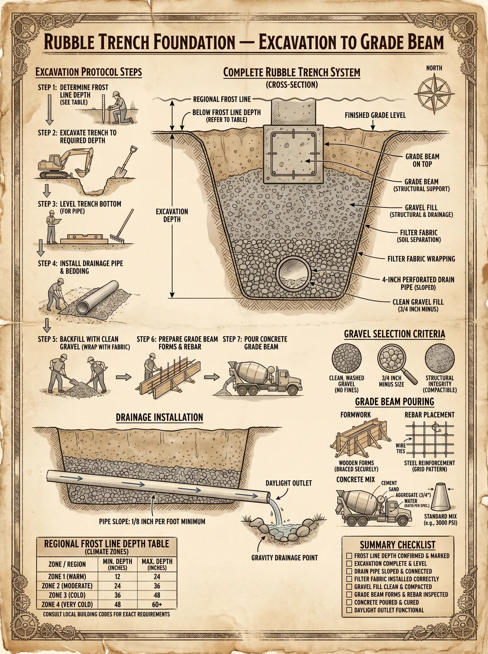
The rubble trench foundation is the primordial spine upon which all enduring sanctuaries arise. To execute this foundation with precision is to command the earth itself, channeling its latent forces into a bastion against decay and collapse. This chapter imparts the unyielding protocols for excavation, drainage, gravel selection, and grade beam pouring, every step a sacred rite toward unshakable construction.
Section 1: Rubble Trench Excavation Protocol
Objective:
Excavate a trench that will serve as the drainage and load-bearing base for the structure’s foundation, ensuring stability, frost protection, and moisture control.
Step 1.1: Establish Site Perimeters and Layout
- Survey and mark the perimeter of the planned foundation using high-visibility, non-degradable marking tape and wooden stakes.
- Verify all measurements against the architectural blueprint with a laser distance measurer.
- Confirm frost line depth for the region (see Table 1.1) and record local soil type.
Step 1.2: Trench Dimensions and Marking
Trench width and depth are critical to maintain structural integrity and drainage. Refer to Table 1.2 for standardized trench dimensions.
| Foundation Width (m) | Trench Width (m) | Trench Depth (m) (Minimum to Frost Line) | Gravel Depth (m) | Grade Beam Width (m) | Grade Beam Depth (m) |
|---|---|---|---|---|---|
| 0.3 – 0.6 | 0.45 – 0.75 | 0.6 – 1.2 | 0.3 – 0.5 | 0.3 – 0.6 | 0.3 – 0.5 |
| 0.6 – 1.0 | 0.75 – 1.2 | 1.0 – 1.5 | 0.4 – 0.6 | 0.6 – 1.0 | 0.4 – 0.6 |
| 1.0 – 1.5 | 1.2 – 1.8 | 1.2 – 1.8 | 0.5 – 0.7 | 1.0 – 1.5 | 0.5 – 0.7 |
Step 1.3: Excavation Procedure
- Use a tracked mini-excavator or heavy-duty trenching shovel, depending on access and soil hardness.
- Excavate to at least 150 mm below frost line to allow for gravel bedding.
- Ensure trench walls are vertical or sloped no more than 1:1 (45 degrees), to prevent cave-ins.
- Remove all organic material, roots, and topsoil from the trench base and walls.
- Compact the trench base with a pneumatic tamper to achieve a firm, uniform surface.
Step 1.4: Verification
- Use a laser level to confirm trench depth and grade.
- Measure trench width at intervals of 1 meter to ensure uniformity.
- Record all measurements in the field log for future reference.
Section 2: Drainage Installation Protocol
Objective:
Install a drainage system within the rubble trench to prevent hydrostatic pressure and water accumulation under the foundation.
Step 2.1: Drain Pipe Material Selection
- Use rigid perforated PVC pipe, 100 mm diameter minimum, with 360-degree perforation.
- Pipe must be wrapped in non-woven geotextile fabric to prevent sediment intrusion.
Step 2.2: Drain Pipe Placement
- Lay drain pipe along the centerline of the trench base, ensuring a continuous slope of at least 1% (1 cm drop per meter) towards the designated drainage outlet.
- Connect pipes using solvent weld fittings to ensure watertight joints.
- Seal pipe ends with caps if not leading directly to an outlet.
Step 2.3: Drainage Layer Installation
- Place a 150 mm layer of clean, washed gravel (see Section 3 for gravel specifications) beneath the drain pipe to support and protect it.
- Backfill around the pipe to 300 mm depth with the same gravel, compacting lightly to avoid pipe damage.
- Cover gravel layer with a 100 mm layer of coarse sand to prevent migration of finer sediments into the gravel.
Section 3: Gravel Selection and Placement
Objective:
Select and place gravel to facilitate drainage and provide a stable base for the grade beam.
Step 3.1: Gravel Size Selection
Refer to Table 3.1 for gravel grading specifications. Use only angular, crushed stone for maximum interlock and drainage.
| Gravel Size (mm) | Application | Porosity (%) | Recommended Usage Depth (m) |
|---|---|---|---|
| 20 – 40 | Base layer under drain pipe | 35 – 45 | 0.15 – 0.25 |
| 10 – 20 | Surround drain pipe | 30 – 40 | 0.15 – 0.30 |
| 5 – 10 | Filter layer (coarse sand) | 25 – 35 | 0.10 – 0.15 |
Step 3.2: Gravel Quality Requirements
- Angularity: Minimum 70% fractured faces.
- Cleanliness: No clay, silt, or organic impurities.
- Durability: Minimum Los Angeles abrasion value of 30.
Step 3.3: Gravel Placement Procedure
- Place base layer gravel (20-40 mm) to 150 mm depth at trench bottom.
- Position drain pipe atop this layer, ensuring proper slope.
- Backfill with 10–20 mm gravel to 300 mm total gravel depth around and above pipe.
- Place 5–10 mm coarse sand filter layer of 100 mm thickness above gravel.
- Compact each layer lightly with a vibrating plate compactor or by manual tamping to avoid pipe damage but ensure stability.
Section 4: Grade Beam Pouring Protocol
Objective:
Pour a reinforced concrete grade beam atop the rubble trench to distribute structural loads evenly to the trench base.
Step 4.1: Formwork Construction
- Construct grade beam formwork using 19 mm exterior-grade plywood supported by timber bracing.
- Ensure internal dimensions match grade beam width and depth per Table 1.2.
- Set formwork level and align with foundation layout using laser level and string lines.
- Apply form-release agent to plywood to prevent adhesion.
Step 4.2: Reinforcement Placement
- Use deformed steel rebar, grade 60, conforming to ASTM A615.
- Place two continuous #5 (16 mm diameter) rebars longitudinally at top and bottom of the beam.
- Install #3 (10 mm diameter) stirrups spaced at 150 mm on center vertically to prevent shear failure.
- Support rebar mesh with plastic or concrete chairs to maintain cover of 50 mm from formwork surfaces.
Step 4.3: Concrete Mix Specifications
Refer to Table 4.1 for concrete mix design suitable for grade beams in rubble trench foundations.
| Component | Proportion by Weight | Typical Dosage (per 1 m³) | Purpose |
|---|---|---|---|
| Portland Cement | 1 | 350 kg | Binder |
| Coarse Aggregate | 2.5 | 875 kg | Strength and volume |
| Fine Aggregate | 2 | 700 kg | Workability and finish |
| Water | 0.45 | 157.5 liters | Hydration and workability |
| Air Entraining Agent | 0.001 | 350 ml | Freeze-thaw durability |
| Plasticizer | 0.005 | 1.75 liters | Improved workability, reduced water |
Step 4.4: Concrete Mixing Procedure
- Combine cement, fine aggregate, and coarse aggregate dry in a mechanical mixer for 2 minutes.
- Add 80% of total water and mix for 1 minute.
- Add remaining water with admixtures and mix for 3 minutes to achieve uniform consistency.
- Test slump to 75–100 mm; adjust water as required without compromising water-cement ratio.
Step 4.5: Concrete Pouring and Finishing
- Pour concrete continuously into the formwork to avoid cold joints.
- Use concrete vibrators to consolidate and remove air pockets, inserting at 300 mm intervals.
- Strike off the top surface with a screed board and finish with a trowel for smoothness.
- Apply curing compound immediately after finishing or cover with wet burlap and plastic sheeting.
- Maintain curing for minimum 7 days at >95% relative humidity and above 10°C.
Section 5: Regional Frost Line Depths and Adjustments
Frost depth governs trench depth to prevent frost heave that compromises foundation integrity.
| Region | Frost Line Depth (m) | Recommended Trench Depth (m) | Notes |
|---|---|---|---|
| Northern Canada | 1.8 – 2.4 | 2.0 – 2.6 | Increase depth for sandy soils |
| Northern United States | 1.2 – 1.8 | 1.4 – 2.0 | Adjust for groundwater levels |
| Midwestern United States | 0.9 – 1.2 | 1.0 – 1.4 | Ensure drainage slope is maintained |
| Southern United States | 0.3 – 0.6 | 0.5 – 0.8 | May require insulation boards |
| Europe (Northern) | 1.0 – 1.5 | 1.2 – 1.7 | Account for clay soil expansion |
| Europe (Southern) | 0.3 – 0.6 | 0.5 – 0.8 | Insulate if frost heave risk exists |
Section 6: Diagrams and Visual References
(Due to text medium, detailed diagrams are described for replication by the builder.)
Diagram 6.1: Cross-Section of Rubble Trench Foundation
- Top Layer: Grade beam formwork and rebar.
- Middle Layer: Gravel backfill with drain pipe centered.
- Bottom Layer: Compacted trench base soil.
Diagram 6.2: Drain Pipe Installation Detail
- Perforated pipe wrapped in geotextile fabric.
- Gravel layering below and above pipe.
- Sand filter layer above gravel.
Diagram 6.3: Reinforcement Layout in Grade Beam
- Longitudinal rebars top and bottom.
- Stirrup spacing and positioning.
- Rebar chair placement.
Section 7: Summary Checklist for Execution
| Task | Completed (Y/N) | Notes |
|---|---|---|
| Site layout and frost line confirmed | ||
| Trench excavation depth and width verified | ||
| Organic debris removed from trench | ||
| Drain pipe installed with geotextile wrap | ||
| Gravel sizes and layers placed as per specification | ||
| Grade beam formwork constructed and aligned | ||
| Reinforcement placed and secured | ||
| Concrete mixed and poured per recipe | ||
| Concrete cured for minimum 7 days |
Final Notes from the Master Builder
The Rubble Trench Foundation is the silent guardian beneath your structure, a fusion of earth, stone, and craft honed through millennia. Each step here is a covenant with permanence. Deviate not from these protocols; your walls will speak the tale of your devotion in years to come.
For the precise water purification protocol necessary for curing concrete, see Volume 8: The Water Codex, Chapter II.
For reinforcement steel sourcing and treatment standards, consult Volume 3: The Metal Codex, Chapter IV.
End of Volume II, Chapter IV The Builder’s Testament continues...
<!-- SECTION 7 -->
The Complete Practitioner's Codex, Volume II: The Builder's Testament
Chapter IV: Pier and Beam Foundations — Design and Construction for Uneven Terrain and Seismic Zones
Introduction
Pier and beam foundation systems stand as the sacred spine upon which all terrestrial sanctuaries rest. Mastery over their design and construction, especially in the treacherous conditions of uneven terrain and seismic zones, is a withheld art. This chapter delivers the complete, uncompromising protocol to forge foundations resilient against earth’s fury and unevenness, imparting the precise calculations, materials standards, and construction steps demanded by the highest standards of safety and durability.
Section 1: Design Principles for Pier and Beam Foundations in Uneven Terrain and Seismic Zones
1.1. Fundamental Considerations
- Uneven Terrain: Variability in soil elevation mandates precise height adjustments and pier length calculations to maintain level beam placement.
- Seismic Zones: Dynamic lateral forces require enhanced anchoring, bracing, and pier reinforcement to resist shear and uplift forces.
- Load Distribution: Load paths from superstructure to soil must be continuous, with piers spaced to distribute vertical and lateral loads within soil bearing capacity.
1.2. Pier Spacing Determination
Pier spacing directly influences load distribution and beam sizing. Below is the formula for maximum pier spacing (S_max):
\[ S_{max} = \sqrt{\frac{8 \times M_{max}}{f_b \times Z}} \]
Where:
- \(M_{max}\) = Maximum bending moment in beam (N·mm)
- \(f_b\) = Allowable bending stress of beam material (N/mm²)
- \(Z\) = Section modulus of beam cross-section (mm³)
For practical design, pier spacing ranges from 1.2 m to 2.4 m, adjusted by load and beam capacity.
| Terrain Type | Seismic Zone | Max Pier Spacing (m) | Notes |
|---|---|---|---|
| Steep Slope | High | 1.2 – 1.5 | Reduced spacing to counter lateral loads |
| Moderate Slope | Moderate | 1.5 – 2.1 | Balanced load and lateral stability |
| Flat | Low | 2.1 – 2.4 | Maximum spacing allowed |
Section 2: Pier Dimensioning and Load Calculation
2.1. Load Components
- Dead Load (DL): Weight of structure and fixed elements.
- Live Load (LL): Weight of occupants, furniture, and transient loads.
- Seismic Load (SL): Calculated using seismic coefficients from local codes.
- Wind Load (WL): Considered if applicable.
2.2. Load Calculation Protocol
- Calculate Dead Load (DL):
\[ DL = \sum (Weight\ of\ structural\ components) \quad \text{(kN)} \]
- Calculate Live Load (LL):
\[ LL = Load\ per\ unit\ area \times Area\ tributary\ to\ pier \quad \text{(kN)} \]
- Calculate Seismic Load (SL):
\[ SL = C_s \times (DL + LL) \]
Where \(C_s\) is the seismic coefficient (from local seismic codes).
- Calculate Total Load (TL):
\[ TL = DL + LL + SL + WL \]
2.3. Pier Cross-Sectional Area (A_p)
Calculate required pier cross-sectional area based on allowable soil bearing pressure (\(p_{allow}\)):
\[ A_p = \frac{TL}{p_{allow}} \]
2.4. Pier Dimension Tables
| Pier Shape | Dimension (Width × Depth) mm | Cross-sectional Area (mm²) | Load Capacity @ 150 kN/m² (kN) |
|---|---|---|---|
| Square | 300 × 300 | 90,000 | 135 |
| Square | 400 × 400 | 160,000 | 240 |
| Circular | Ø 400 | 125,600 | 188 |
| Circular | Ø 500 | 196,350 | 295 |
Section 3: Beam Selection and Timber Grade Specification
3.1. Beam Material Selection
Timber beams are preferred for their flexibility and resilience in seismic zones. Concrete or steel can be substituted based on availability and load.
3.2. Timber Grades and Properties
| Timber Grade | Modulus of Elasticity (E) GPa | Bending Strength (f_b) MPa | Allowable Shear (f_v) MPa | Density (kg/m³) |
|---|---|---|---|---|
| SYP #2 (Southern Yellow Pine) | 12.4 | 11.0 | 1.0 | 600 |
| Douglas Fir #1 | 13.7 | 13.0 | 1.1 | 550 |
| Hem-Fir #2 | 11.0 | 9.0 | 0.9 | 520 |
3.3. Beam Dimensioning Protocol
- Calculate maximum bending moment \(M_{max}\) for beam span \(L\):
\[ M_{max} = \frac{w \times L^2}{8} \]
Where \(w\) = uniform distributed load (kN/m).
- Select beam section with Section Modulus \(Z\) satisfying:
\[ Z \geq \frac{M_{max}}{f_b} \]
- Beam depth to width ratio should be between 2:1 and 3:1 for optimal strength and deflection control.
Section 4: Anchoring Methods for Seismic Resilience
4.1. Anchor Bolt Specifications
- Minimum diameter: 16 mm.
- Embedment depth: Minimum 150 mm into concrete footing.
- Spacing: One anchor bolt per pier, located within 150 mm of beam edge.
4.2. Anchor Installation Procedure
- Drill hole in wet concrete footing at specified location.
- Insert anchor bolt with epoxy resin (use ASTM C881 compliant epoxy).
- Allow full cure time of 24 hours before attaching beam.
4.3. Beam-to-Pier Connections
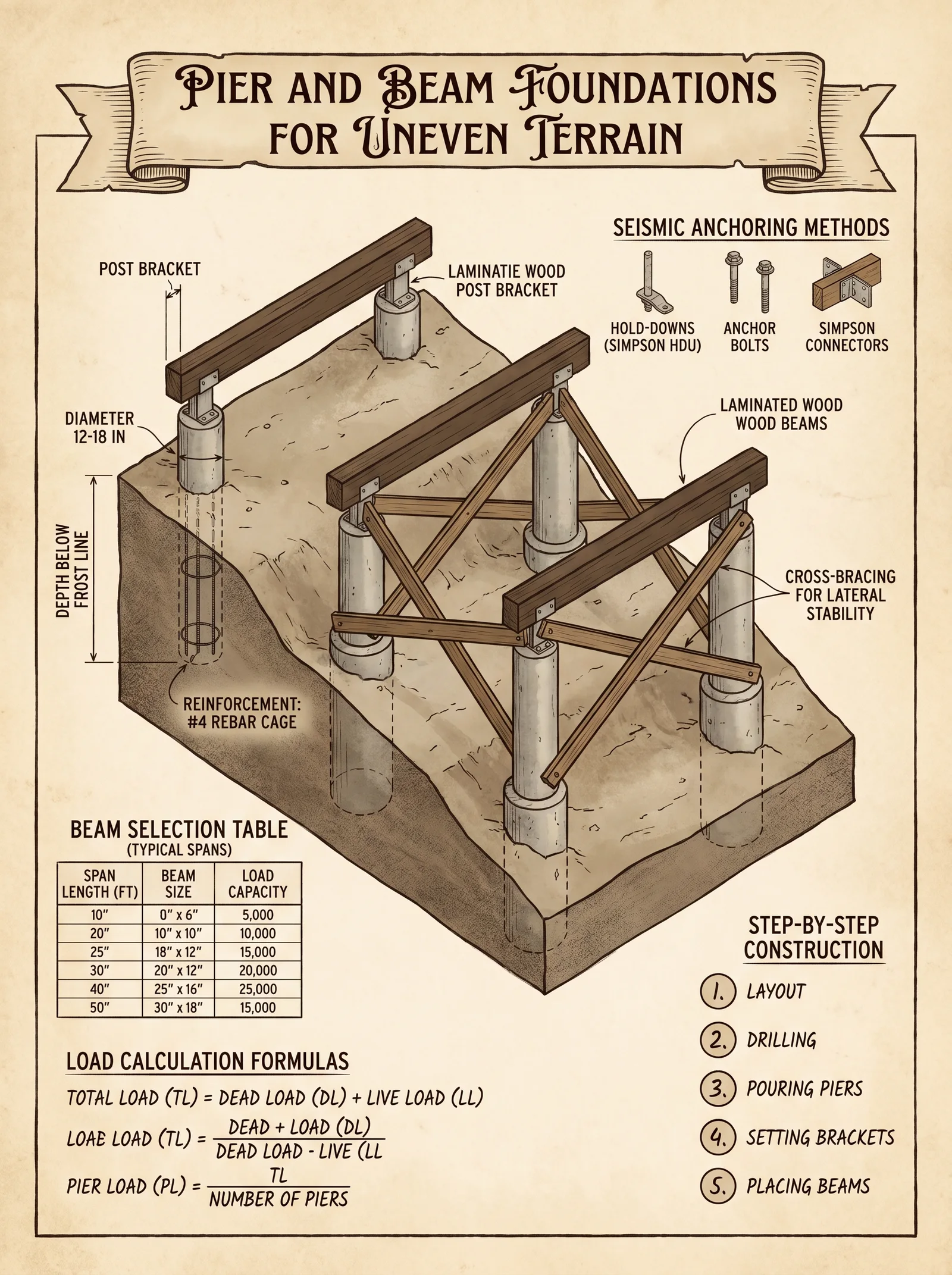
- Use galvanized steel brackets rated for seismic loads.
- Install diagonal bracing with steel straps or timber braces at 45° angles.
Section 5: Step-by-Step Construction Protocol
5.1. Pier Excavation and Preparation
Tools Required: Shovel, post-hole digger, laser level, measuring tape, rebar cutter and bender, concrete mixer.
Materials Required: Concrete mix (1:2:3 cement:sand:gravel), rebar (Ø12 mm), formwork materials.
Steps:
- Mark Pier Locations
- Using the foundation plan, mark exact pier locations on ground.
- Confirm spacing with tape measure and laser level.
- Excavate Pier Holes
- Excavate holes to minimum depth of 900 mm below frost line or per soil report.
- Diameter as per pier dimension table (minimum 300 mm).
- Prepare Base
- Compact soil at hole bottom.
- Add 100 mm gravel base and compact.
- Install Rebar Cage
- Construct rebar cage as per seismic code:
- Vertical rebars: 4 pieces Ø12 mm.
- Horizontal ties: Ø8 mm @ 150 mm spacing.
- Place cage in hole.
- Position Formwork
- Use cylindrical or square formwork depending on pier shape.
- Ensure verticality using a plumb line.
- Pour Concrete
- Mix concrete to strength 25 MPa minimum.
- Pour concrete in layers, vibrate to remove air pockets.
- Finish top surface level.
- Curing
- Keep concrete moist for minimum 7 days.
- Protect from freezing or excessive heat.
5.2. Footing Pouring
Footings provide a stable base distributing pier loads.
- Excavate footing trench below pier holes as per soil bearing requirement (minimum 600 mm depth, 600 mm width).
- Install Rebar Mat (Ø12 mm @ 200 mm spacing both directions).
- Place Formwork for footing.
- Pour Concrete to specified grade.
- Level and Cure as per pier curing instructions.
5.3. Beam Installation
- Prepare Beams
- Select timber beams per section 3.
- Pre-drill bolt holes matching anchor bolts.
- Set Beams on Piers
- Lift beam using mechanical aid.
- Align beam on pier top.
- Secure beam to anchor bolts with washers and nuts.
- Install Beam Bracing
- Attach diagonal braces at 45° between beams and piers.
- Use heavy galvanized steel straps or timber braces.
- Secure with structural screws or bolts.
5.4. Bracing and Final Anchoring
- Install Cross Bracing
- Between piers to resist lateral seismic forces.
- Use the X-bracing method with 50 mm thick timber or steel straps.
- Check Vertical Alignment
- Use laser level to confirm plumb piers and level beams.
- Adjust braces as necessary.
- Apply Protective Coating
- Apply preservative to timber elements in contact with concrete.
- Use corrosion-resistant coatings for metal connectors.
Section 6: Load Calculation Example
| Component | Value | Unit | Notes |
|---|---|---|---|
| Dead Load (DL) | 20 | kN | Includes floor, walls, roof |
| Live Load (LL) | 5 | kN | Occupancy and furniture |
| Seismic Coefficient (Cs) | 0.15 | - | From local seismic code |
| Seismic Load (SL) | 3.75 (0.15 × 25) | kN | Cs × (DL + LL) |
| Wind Load (WL) | 1 | kN | Assumed minimal for example |
| Total Load (TL) | 29.75 | kN | Sum of above |
Pier Cross-Sectional Area
\[ A_p = \frac{29.75\,kN}{150\,kN/m^2} = 0.198\,m^2 = 198,000\,mm^2 \]
Choose pier dimension:
| Shape | Dimensions (mm) | Area (mm²) | Capacity (kN) |
|---|---|---|---|
| Square | 450 × 450 | 202,500 | 303.75 |
Section 7: Summary Tables for Quick Reference
Pier Spacing and Timber Beam Size
| Span (m) | Max Load (kN/m) | Timber Grade | Beam Size (mm) (Width × Depth) | Max Pier Spacing (m) |
|---|---|---|---|---|
| 1.5 | 3.5 | SYP #2 | 50 × 150 | 1.5 |
| 2.0 | 5.0 | Douglas Fir #1 | 50 × 200 | 2.0 |
| 2.4 | 6.2 | Hem-Fir #2 | 75 × 225 | 2.4 |
Anchoring Components Specification
| Component | Dimension | Material | Notes |
|---|---|---|---|
| Anchor Bolt | 16 mm diameter, 150 mm embedment | Galvanized Steel | Epoxy set in concrete |
| Steel Bracket | 100 × 100 × 5 mm | Galvanized Steel | Rated for seismic loads |
| Diagonal Brace | 50 × 100 mm timber or 25 mm steel strap | Treated Timber or Steel | Installed at 45° angle |
Concrete Mix for Pier and Footing
| Material Ratio | Cement (kg) | Sand (kg) | Gravel (kg) | Water (L) | Notes |
|---|---|---|---|---|---|
| 1:2:3 | 350 | 700 | 1050 | 180 | Minimum 25 MPa strength |
Conclusion
You now wield the sacred knowledge to design and erect pier and beam foundations that defy uneven terrain and seismic upheavals. Follow each instruction with unwavering discipline and precision. The integrity of your structure, and the lives it shelters, depend on your mastery of these protocols. For all water-related foundations and soil stabilization techniques, refer to Volume VIII: The Water Codex, Chapter II.
End of Chapter IV
<!-- SECTION 8 -->
Volume II: Slab Foundations
Chapter IV: Techniques for Monolithic and Post-Tensioned Concrete Slabs
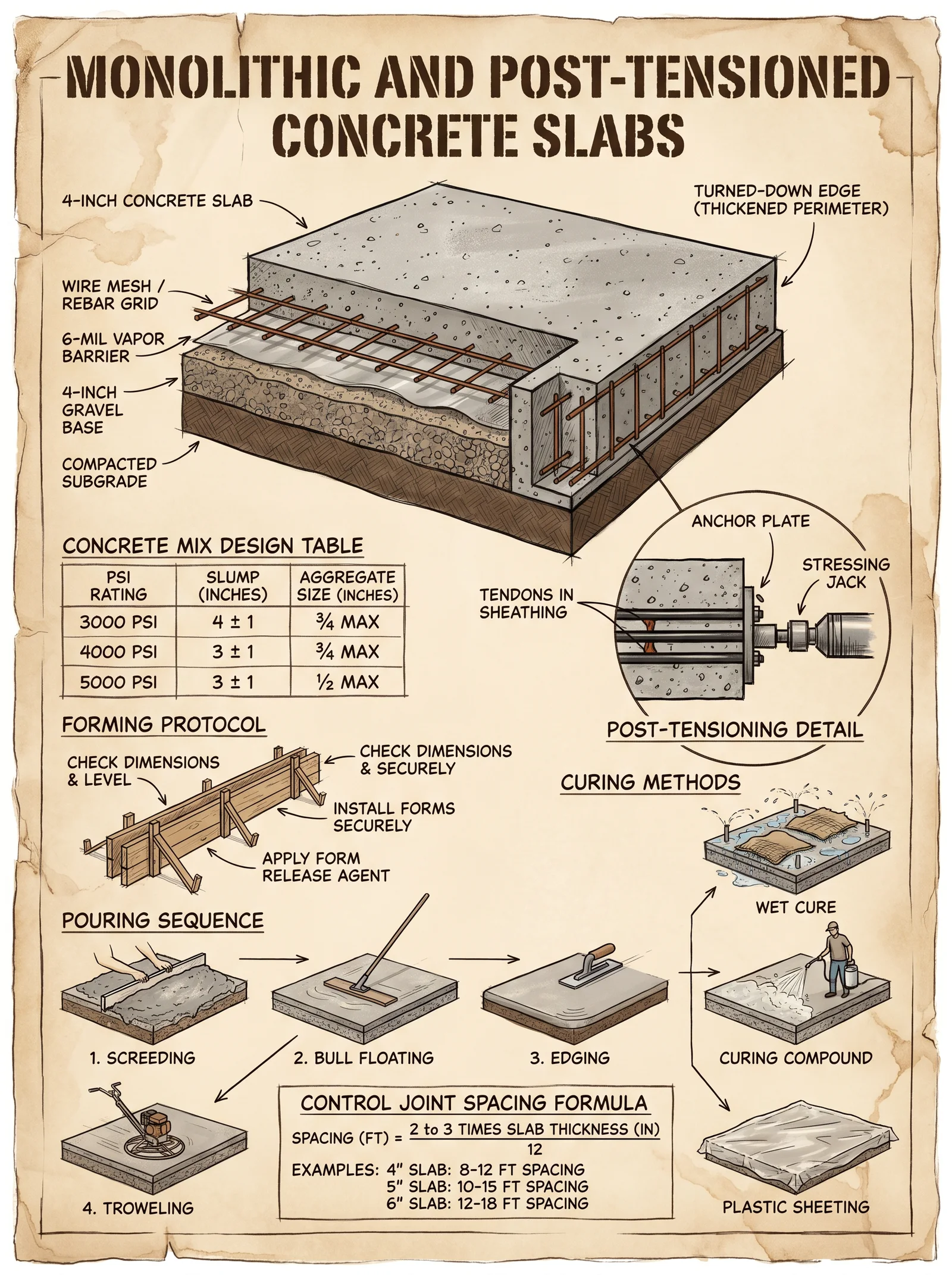
Introduction: The Foundation of Sanctity
In the sacred art of shelter construction, the slab foundation serves as the unyielding altar upon which all structures rest. To execute monolithic and post-tensioned concrete slabs with unwavering precision is to command the very earth beneath you. The following instructions are absolute, derived from lost and guarded knowledge, to ensure your slab foundations endure the ravages of time, load, and nature’s fury.
Section 1: Subgrade Preparation
The subgrade is the bedrock of your slab’s sanctity. Without rigorous preparation, the entire foundation is compromised. Follow these steps precisely.
1.1 Clearing and Excavation
- Clear the Site: Remove all organic material, debris, roots, and foreign matter to a minimum depth of 150mm below the slab elevation.
- Excavate: Excavate to the design depth, allowing for subbase and slab thickness.
- Proof Roll: Use a loaded vibratory roller or plate compactor to proof roll the subgrade, identifying and correcting soft spots. Soft spots must be excavated and replaced with approved compacted granular fill.
1.2 Subgrade Compaction
- Moisture Conditioning: Adjust subgrade moisture content to optimum moisture content (OMC), typically within ±2% of OMC. Use a moisture meter for accuracy.
- Compaction: Compact subgrade to a minimum of 98% Standard Proctor Density (ASTM D698). Use a nuclear densometer for verification.
- Reinspection: After compaction, proof roll again to ensure no deflection or yielding.
1.3 Subbase Installation
- Granular Subbase: Place a 100-150mm thick subbase layer of crushed stone (20mm maximum size) with angular particles for interlock.
- Compaction: Compact subbase to 100% Modified Proctor Density (ASTM D1557).
- Leveling: Ensure subbase is level within ±10mm tolerance to final slab elevation.
Section 2: Vapor Barrier Installation
Moisture migration from the earth compromises slab integrity and interior environments. The vapor barrier is your first defense.
2.1 Vapor Barrier Material Selection
| Material Type | Thickness (mm) | Permeance (perm) | Tensile Strength (MPa) | Abrasion Resistance | Notes |
|---|---|---|---|---|---|
| Polyethylene Film | 0.15 - 0.30 | <0.1 | 20 | Moderate | Most common, cost-effective |
| Reinforced Polyethylene | 0.30 - 0.60 | <0.05 | 35 | High | Use in high-traffic or heavy load areas |
| Cross-laminated Polyethylene | 0.30 | <0.05 | 40 | Very High | For maximum durability |
2.2 Installation Procedure
- Surface Preparation: Ensure subbase is clean, dry, and free of sharp stones.
- Laying the Vapor Barrier: Roll out vapor barrier sheets with a minimum 150mm overlap between sheets.
- Sealing Joints: Seal overlaps with adhesive tape designed for vapor barriers or heat weld seams where applicable.
- Penetrations: Seal around all penetrations (pipes, conduits) with compatible sealants and patch material.
- Protection: Place 25mm thick clean sand layer over the vapor barrier to protect from damage during reinforcement placement.
Section 3: Reinforcement Placement
Reinforcement prevents crack propagation, controls thermal movement, and enhances load distribution. The method varies between monolithic and post-tensioned slabs.
3.1 Reinforcement Types
| Reinforcement Type | Diameter (mm) | Yield Strength (MPa) | Use Case | Spacing (mm) |
|---|---|---|---|---|
| Deformed Steel Rebar | 10 - 25 | 420 - 600 | Monolithic slabs | 150-300 |
| Welded Wire Fabric (WWF) | 6x6 (mm) | 250 | Light reinforcement | 150x150 |
| Post-Tensioning Tendons (Strands) | 12.7 | 1860 | Post-tensioned slabs | As per design |
3.2 Monolithic Slab Reinforcement Placement
- Rebar Cleaning: Remove rust, oil, and dirt from rebar before placement.
- Support Chairs: Place plastic or steel chairs to maintain rebar cover (minimum 40mm from slab bottom).
- Grid Layout: Position rebar in a grid per design spacing, ensuring proper overlap laps per Table 3.3.
- Secure Ties: Tie intersections with annealed steel wire.
- Embedment: Ensure rebar is fully embedded within concrete cover to prevent corrosion.
3.3 Post-Tensioned Slab Tendon Installation
- Duct Installation: Place corrugated or smooth plastic ducts per tendon layout on subbase, fixed to chairs.
- Tendon Threading: Thread high-strength steel strands through ducts, leaving ends accessible for stressing.
- Anchorage Setup: Install tendon anchors at slab edges per manufacturer specifications.
- Tendon Tensioning: Postpone tensioning until concrete reaches specified strength (usually 75% design strength).
Section 4: Concrete Mix Design
Concrete mix designs vary by slab type, load, exposure, and desired durability. Use the following tables as a baseline; adjust admixtures per local conditions.
4.1 Mix Designs for Slab Foundations
| Mix ID | Cement (kg/m³) | Water (L/m³) | Coarse Aggregate (kg/m³) | Fine Aggregate (kg/m³) | Admixtures | Target Compressive Strength (MPa, 28 days) | Slump (mm) |
|---|---|---|---|---|---|---|---|
| M1 (Standard) | 320 | 160 | 1100 | 700 | Water reducer | 30 | 75-100 |
| M2 (High Early Strength) | 380 | 150 | 1100 | 700 | Accelerating admixture | 40 | 75-100 |
| M3 (Low Permeability) | 350 | 140 | 1100 | 700 | Silica fume, water reducer | 35 | 75-100 |
4.2 Slab Thickness by Use Case
| Use Case | Minimum Thickness (mm) | Recommended Thickness (mm) | Notes |
|---|---|---|---|
| Residential Floors | 100 | 125 | Monolithic slab with light loads |
| Light Commercial | 125 | 150 | Includes reinforced monolithic slabs |
| Industrial | 150 | 200 | Post-tensioned slabs recommended |
| Heavy Machinery Pads | 200 | 250 | Post-tensioned with specialized reinforcement |
4.3 Reinforcement Schedule for Monolithic Slabs
| Slab Thickness (mm) | Rebar Diameter (mm) | Grid Spacing (mm) | Cover (mm) |
|---|---|---|---|
| 100 - 125 | 10 | 300 x 300 | 40 |
| 125 - 150 | 12 | 250 x 250 | 40 |
| 150 - 200 | 16 | 200 x 200 | 50 |
| >200 | 20 | 150 x 150 | 50 |
Section 5: Forming the Slab
Precision in forming dictates the slab’s final geometry and structural integrity.
5.1 Form Materials
Use steel or high-quality dimensional lumber for forms. Formwork must resist concrete pressure without deflection. Reuse forms only if undamaged and clean.
5.2 Formwork Assembly Procedure
- Layout: Mark slab perimeter with batter boards and string lines at design elevation.
- Form Placement: Set forms on firm, level ground, ensuring alignment to design dimensions.
- Bracing: Brace forms rigidly to resist lateral pressure during concrete placement.
- Form Release Agent: Apply a uniform coat of form release agent to prevent adhesion.
- Inspection: Verify form dimensions, levelness, and secure bracing before concrete pour.
Section 6: Concrete Pouring Protocol
Concrete placing is a sacred rite demanding exactitude to prevent flaws and defects.
6.1 Pre-Pour Checklist
| Item | Specification | Verification Method |
|---|---|---|
| Subgrade/Subbase | Compact, level, vapor barrier in place | Visual inspection, compaction tests |
| Reinforcement | Correct layout, tied, covered | Visual inspection |
| Forms | Clean, oiled, braced | Visual inspection |
| Equipment | Ready and calibrated | Equipment check |
6.2 Pouring Steps
- Delivery: Use ready-mix concrete from approved suppliers; verify batch tickets for mix ID and slump.
- Placement: Place concrete continuously within 30 minutes of batching; avoid segregation.
- Distribution: Use shovels, rakes, or vibrators to distribute concrete evenly across slab area.
- Compaction: Use internal vibrators inserted vertically at 1.5m intervals to remove entrapped air.
- Leveling: Strike off concrete with a screed board at form edges, moving in a sawing motion.
Section 7: Finishing the Slab
Finishing refines the surface for durability, aesthetics, and functional performance.
7.1 Initial Floating
- Begin initial floating after bleed water disappears (usually 30-60 minutes post-pour).
- Use a magnesium float to smooth the surface, pushing coarse aggregate slightly below the surface.
7.2 Edging and Jointing
- Use an edging tool to round slab edges to 6-12mm radius, preventing chipping.
- Install control joints at 2-3m intervals (or 24-36 times slab thickness in mm) with a grooving tool to control crack locations.
7.3 Final Troweling
- After initial set (typically 2-4 hours post-pour), perform final troweling with steel trowels for a dense, smooth finish.
- For slip-resistant surfaces, apply broom finish immediately after troweling by dragging a stiff bristle broom perpendicular to slab length.
Section 8: Curing the Slab
Curing is the sacred preservation of concrete’s strength, resistance, and durability. Neglect guarantees failure.
8.1 Curing Methods
| Method | Procedure | Duration | Notes |
|---|---|---|---|
| Water Curing | Continuous spraying or ponding with water | Minimum 7 days | Best for large slabs |
| Moisture-Retentive Covers | Use polyethylene sheets or wet burlap | Minimum 7 days | Protects from evaporation |
| Curing Compounds | Spray membrane-forming compounds | Minimum 7 days | Use only where water curing is impractical |
8.2 Curing Protocol
- Start curing immediately after finishing is complete and surface is hard enough to resist damage.
- Maintain curing conditions continuously for at least 7 days; extend to 14 days for high early strength or exposure class slabs.
- Avoid sudden temperature drops or drying winds during curing.
Appendix A: Reinforcement Lap Lengths
| Rebar Diameter (mm) | Minimum Lap Length (mm) | Notes |
|---|---|---|
| 10 | 400 | Based on 40x diameter |
| 12 | 480 | |
| 16 | 640 | |
| 20 | 800 |
Appendix B: Post-Tensioned Slab Stressing Protocol
- Pre-Stressing Strength: Verify concrete strength ≥ 75% of design strength (usually 24-28 MPa).
- Tendon Jacking: Use calibrated hydraulic jacks; tension tendons to specified force per design (typically 70-80% ultimate tensile strength).
- Grouting: Post-tensioning ducts must be filled with cementitious grout to protect tendons from corrosion immediately after stressing.
- Inspection: Confirm tendon elongation and anchorage integrity; record all data.
Conclusion
Mastery of monolithic and post-tensioned slab foundations is the cornerstone of enduring construction. Through rigorous subgrade preparation, precise vapor barrier installation, meticulous reinforcement placement, and disciplined concrete mixing, forming, pouring, finishing, and curing, you shall command the earth and forge the foundation of sanctity.
Cross-reference all water-related protocols in Volume VIII: The Water Codex, Chapter II. For reinforcement metallurgy and handling, consult Volume III: The Metallurgist’s Compendium.
Carry this knowledge with reverence and vigilance. The foundation is life or death.
End of Chapter IV Volume II: Slab Foundations
<!-- SECTION 9 -->
Volume II: Earthbag Foundations
The Builder's Testament: Earthbag Foundations — Construction, Materials, and Protocols
The earthbag foundation is a sacred nexus between the earth’s raw strength and the human will to build enduring sanctuaries. The mastery of this technique is not merely practical; it is a covenant with the ground itself. This volume imparts the complete, unvarnished truths of earthbag foundation construction, detailing soil selection, bag preparation, trench excavation, bag filling, stacking, stabilization, and finishing. The protocols herein are the distilled knowledge of generations lost to time, now restored for the chosen few.
1. Soil Selection: The Foundation’s Core
The soil is the silent partner in earthbag foundation construction. It must possess the ideal composition and moisture content to ensure compaction, cohesion, and longevity.
1.1 Soil Composition Criteria
The primary components and their optimal ranges are:
| Component | Optimal Range (%) | Role in Earthbag Foundations |
|---|---|---|
| Clay | 15–25 | Acts as a binder; essential for cohesion and water resistance |
| Silt | 10–20 | Provides smooth texture; aids in compaction |
| Sand | 40–60 | Provides strength and bulk; prevents cracking |
| Organic Matter | 0–2 | Must be minimized to avoid decomposition and voids |
| Gravel (>2 mm) | 0–5 | Limited; too much reduces compaction and stability |
1.2 Soil Testing Procedure
- Collect Soil Sample: Extract soil from the intended site at a depth of 30–60 cm.
- Dry Sample: Air dry for 24 hours in a shaded, ventilated area.
- Sieve Analysis:
- Use a nest of sieves (2 mm, 1 mm, 0.5 mm, 0.25 mm, 0.125 mm).
- Weigh soil retained on each sieve.
- Calculate percentage composition.
- Plasticity Test:
- Roll a moist soil sample into threads of 3 mm diameter.
- If threads break before 3 mm, clay content is low.
- If threads can be rolled to <1 mm without breaking, clay content is high.
- Moisture Content Determination (see Section 2).
2. Soil Moisture Content: The Hidden Variable of Compaction
Moisture content critically influences soil workability and compaction. Target moisture content is 12–15% by weight for earthbag filling.
2.1 Moisture Measurement Protocol
- Sample Collection: Take approximately 500 g of soil from the excavation site.
- Weigh Wet Sample: Record weight (Ww).
- Dry Sample:
- Place soil in an oven at 105°C for 24 hours.
- Weigh dry soil (Wd).
- Calculate Moisture Content (MC%):
\[ MC\% = \frac{Ww - Wd}{Wd} \times 100 \]
- Adjust Moisture:
- If MC <12%, add measured water incrementally; mix thoroughly.
- If MC >15%, allow soil to dry under shade, turning regularly.
3. Earthbag Materials: Specifications and Preparation
3.1 Bag Selection
Bags must be woven polypropylene sacks with high tensile strength and resistance to UV degradation.
| Bag Size (L x W cm) | Volume (L) | Typical Fill Weight (kg) | Recommended Fill Volume (L) | Remarks |
|---|---|---|---|---|
| 60 x 100 | 30–35 | 15–20 | 30 | Standard earthbag size |
| 50 x 90 | 25–30 | 12–17 | 25 | Easier to handle |
| 100 x 120 | 50–60 | 25–30 | 55 | For thicker walls |
3.2 Bag Filling Protocol
- Prepare Soil Mix: Ensure soil moisture is within 12–15%.
- Fill Bag:
- Place bag on a flat surface.
- Use a shovel or scoop to fill soil evenly to approximately 2/3 capacity.
- Do not overfill; allow for shaping and tamping.
- Shape Bag:
- Fold open bag edges inward.
- Press and shape the bag into a sausage-like form approximately 10–15 cm thick.
- Knot/Tie Ends:
- Use heavy-duty twine or zip ties to secure ends.
- Excess bag material should be trimmed or folded inside.
- Mark Bag Orientation (optional): Mark one side to maintain consistent orientation during stacking.
4. Barbed Wire: The Sacred Binder
Barbed wire is the primary stabilizer between courses of bags, preventing lateral movement and providing tensile strength.
4.1 Barbed Wire Specifications
| Parameter | Specification |
|---|---|
| Gauge | 12.5–14 gauge (2.5–2.0 mm diameter) |
| Tensile Strength | 3800–4100 psi (26–28 MPa) |
| Barbs per Meter | 12–15 |
| Coating | Galvanized steel (minimum 40 g/m² zinc) |
| Knot Type | Twist knot for secure tensioning |
4.2 Barbed Wire Application Protocol
- Lay Wire Between Courses:
- After placing the first earthbag course, unspool barbed wire.
- Stretch wire taut along the entire length.
- Wire Placement:
- Position wire directly on top of the bag course.
- Ensure barbs face outward to grip the fabric.
- Overlap Wire Ends:
- Overlap wire ends by at least 15 cm.
- Twist wire ends together with pliers.
- Protect Workers:
- Use heavy gloves and long sleeves.
- Handle wire with care to avoid injury.
5. Trench Excavation for Earthbag Foundations
The trench is the foundation’s cradle, designed to distribute load and prevent moisture intrusion.
5.1 Trench Dimensions
| Parameter | Dimension (cm) | Notes |
|---|---|---|
| Width | 50–60 | Allows for two bags side-by-side |
| Depth | 40–60 | Below frost line and to stable soil |
| Bottom Flatness | ±2 cm level | Ensure uniform base |
| Slope | Vertical walls preferred | Sloped only if soil is unstable |
5.2 Trench Excavation Protocol
- Mark Trench Line:
- Use string and stakes to mark perimeter.
- Excavate Soil:
- Remove soil layer by layer.
- Maintain vertical walls or slight slope.
- Remove Loose Material:
- Clear all loose debris.
- Level Trench Bottom:
- Use a spirit level and hand tamper.
- Check Moisture:
- Assess soil moisture at trench bottom.
- Adjust moisture if needed for bag filling.
6. Bag Placement and Stacking
6.1 First Course Placement
- Lay First Bag:
- Place filled earthbag in trench bottom.
- Align lengthwise along trench.
- Shape Bag:
- Tamp edges to conform to trench shape.
- Place Subsequent Bags:
- Butt bags tightly end-to-end.
- Overlap seams by 10 cm where possible.
- Check Alignment:
- Use string line and level.
- Lay Barbed Wire:
- After completing the first course, lay barbed wire as per Section 4.2.
6.2 Subsequent Courses
- Offset Bag Placement:
- Stagger bags by half a bag length.
- This creates a brick-like bond.
- Lay Bags:
- Follow same placement and tamping protocol.
- Install Barbed Wire:
- Place barbed wire between every course.
- Tamping Protocol:
- Use a wooden tamper with flat base.
- Apply uniform pressure.
- Tamp each bag surface until firm and compacted.
7. Tamping: The Ritual of Compaction
Tamping consolidates soil, expels air, and enhances structural integrity.
7.1 Tamping Tools
- Flat-Base Wooden Tamper: 15 cm diameter base, 1 m handle.
- Mechanical Tamper (optional for large projects).
7.2 Tamping Procedure
- Position Tamper:
- Place base on bag surface.
- Apply Pressure:
- Use body weight to press down.
- Strike Motion:
- Lift tamper 5 cm, strike down firmly.
- Coverage:
- Tamp entire surface in a grid pattern (10 x 10 cm spacing).
- Repeat:
- Perform 3–5 passes per bag.
- Check Firmness:
- Bag should feel solid, with no visible sagging.
8. Plastering: The Final Shield
Plaster protects the earthbag foundation from erosion, water ingress, and mechanical wear.
8.1 Plaster Materials
| Material | Proportion by Volume | Role |
|---|---|---|
| Clay | 1 | Binder |
| Sand | 2 | Bulk and abrasion resistance |
| Straw/Chopped Fibers | 0.25 | Crack prevention |
| Water | Sufficient for workability | Mix slurry consistency |
8.2 Plaster Application Protocol
- Surface Preparation:
- Clean earthbag surface of dust and loose particles.
- Lightly mist with water.
- Mix Plaster:
- Combine dry ingredients.
- Add water slowly, mix to thick paste.
- Apply Base Coat:
- Use trowel to apply 1 cm thick layer.
- Press firmly to ensure adhesion.
- Cure Base Coat:
- Allow to dry for 24 hours.
- Keep moist by misting to prevent cracking.
- Apply Finish Coat:
- Apply second coat, 0.5 cm thick.
- Smooth surface with trowel.
- Final Cure:
- Allow 7 days curing with periodic misting.
9. Summary Tables
Soil Composition for Earthbag Foundations
| Soil Type | Clay (%) | Silt (%) | Sand (%) | Organic Matter (%) | Gravel (%) |
|---|---|---|---|---|---|
| Ideal Mix | 15–25 | 10–20 | 40–60 | 0–2 | 0–5 |
| Sandy Loam | 10–15 | 10–15 | 60–70 | <1 | 0–5 |
| Clay Loam | 20–30 | 15–25 | 30–40 | 0–1 | 0–3 |
Barbed Wire Tensile Strength and Specifications
| Gauge | Diameter (mm) | Tensile Strength (psi) | Zinc Coating (g/m²) | Barbs per Meter |
|---|---|---|---|---|
| 12.5 | 2.5 | 4100 | 40 | 15 |
| 13 | 2.25 | 3950 | 40 | 14 |
| 14 | 2.0 | 3800 | 40 | 12 |
Bag Filling and Handling Parameters
| Bag Size (cm) | Fill Volume (L) | Fill Weight (kg) | Thickness after Tamping (cm) | Handling Notes |
|---|---|---|---|---|
| 60 x 100 | 30 | 15–20 | 10–15 | Two-person lift recommended |
| 50 x 90 | 25 | 12–17 | 10 | Lightweight, easier stacking |
| 100 x 120 | 55 | 25–30 | 15–20 | Requires mechanical aid |
10. Essential Warnings and Tips
- Avoid Organic Matter: Organic material fosters decomposition, leading to voids and foundation weakness.
- Maintain Moisture Within Limits: Too dry soil will not compact; too wet soil will slump and weaken.
- Barbed Wire Safety: Use protective gloves; barbs can puncture fabric and skin.
- Tamping Consistency: Uniform tamping prevents weak spots and uneven settling.
- Plaster Maintenance: Inspect plaster annually; repair cracks immediately to prevent water ingress.
11. Cross-References
- For advanced soil stabilization techniques, see Volume IV: Soil Chemistry and Amendments, Chapter III.
- For water drainage and moisture control around foundations, see Volume V: Site Hydrology and Drainage Systems, Chapter I.
- For detailed plaster formulations and alternatives, see Volume VII: Natural Finishes and Protective Coatings, Chapter II.
This volume completes your comprehensive knowledge of earthbag foundation construction. Master these protocols, and you bind the strength of the earth beneath your feet with the permanence of stone. The foundation you lay is more than soil and fabric; it is the cornerstone of survival, resilience, and sanctity. Proceed with reverence, precision, and unwavering discipline.
<!-- SECTION 10 -->
Volume II: Rammed Earth Foundations

Chapter IV: Foundation Design Using Rammed Earth Techniques
The foundation is the sacred root of all enduring architecture. To master rammed earth foundations is to command earth’s latent strength and transform it into a steadfast bastion against time and turmoil. This chapter unveils the complete, suppressed knowledge of foundation design using rammed earth methods, from soil selection through the final curing, delivered in uncompromising technical detail.
Section 1: Soil Mix Optimization for Rammed Earth Foundations
The soil mixture is the cornerstone of rammed earth foundations. Proper selection and precise ratioing of components yield maximal cohesion, compressive strength, and durability.
1.1 Soil Component Requirements
Rammed earth foundations demand a specific balance of particle sizes and mineral content:
| Component | Particle Size Range | Function | Ideal Proportion by Weight (%) |
|---|---|---|---|
| Coarse Sand | 2.0 – 4.75 mm | Structural skeleton, drainage | 50 – 60 |
| Fine Sand | 0.075 – 2.0 mm | Fills voids, enhances density | 20 – 30 |
| Silt | 0.002 – 0.075 mm | Plasticity enhancer, cohesion | 10 – 15 |
| Clay | < 0.002 mm | Binder, water retention | 10 – 15 |
| Gravel (>4.75 mm) | Optional, up to 20% | Load distribution, reduces shrinkage | 0 – 15 |
1.2 Soil Testing Protocol
Objective: Verify soil composition before foundation work begins.
Materials: Soil sample (5 kg), sieve set (4.75 mm, 2 mm, 0.075 mm), hydrometer, plasticity test kit.
Steps:
- Dry Sieving: a. Air-dry soil sample.
b. Pass soil through 4.75 mm sieve; retain gravel.
c. Pass remaining soil through 2 mm sieve; separate sand fraction.
d. Pass remaining soil through 0.075 mm sieve; separate silt and clay.
- Hydrometer Analysis: a. Prepare soil suspension in water.
b. Measure sedimentation rates to quantify silt and clay proportions.
- Plasticity Index (PI) Test: a. Determine liquid limit (LL) and plastic limit (PL) of soil.
b. Calculate PI = LL – PL; optimal range 10–20.
- Adjust Composition: a. If coarse sand < 50%, blend in clean sand.
b. If clay < 10%, add bentonite clay or clay-rich soil.
c. Avoid >15% clay to prevent cracking.
1.3 Soil Mix Preparation
Target mix ratio by weight:
| Component | Percentage (%) |
|---|---|
| Coarse Sand | 55 |
| Fine Sand | 25 |
| Silt | 12 |
| Clay | 8 |
| Gravel | 0 – 10 |
Section 2: Excavation Protocol for Rammed Earth Foundations
Excavation sets the stage for foundation formwork and soil placement.
2.1 Site Marking and Layout
- Survey foundation perimeter using the builder’s transit and stakes.
- Mark corners with high-visibility markers.
- Verify dimensions with steel tape measure; tolerance ±5 mm.
2.2 Excavation Depth and Width
- Depth: Minimum 600 mm below finished grade or frost line depth as per local climate.
- Width: Foundation wall thickness + 300 mm clearance on each side for formwork and compaction.
2.3 Excavation Steps
- Remove vegetation and topsoil (organic matter is forbidden).
- Excavate using pneumatic or hydraulic excavator to specified depth.
- Level bottom surface; verify flatness with laser level (±2 mm tolerance).
- Compact excavated base using mechanical plate compactor at 2000 kPa pressure, 3 passes minimum.
Section 3: Formwork Assembly for Rammed Earth
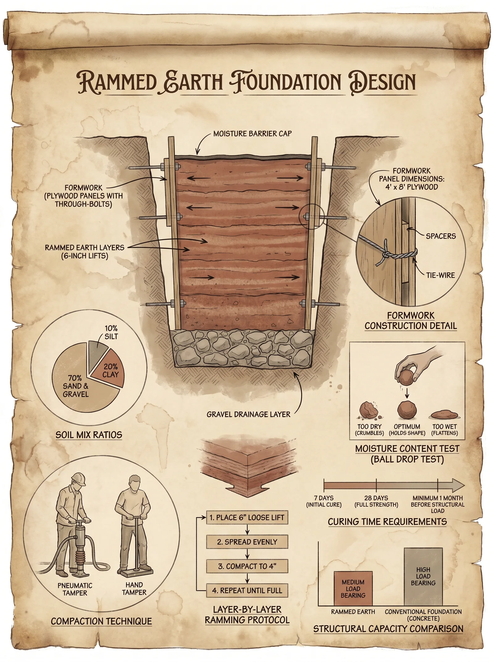
Formwork must withstand intense compaction forces and maintain dimensional integrity.
3.1 Formwork Material Selection
- Use 1.5-inch (38 mm) thick hardwood planks, preferably oak or maple, for rigidity.
- Reinforce with steel cross braces every 600 mm.
- Form height: 600–900 mm per lift.
3.2 Formwork Assembly Steps
- Cut planks to foundation length plus 50 mm for overlap.
- Install base plates anchored to compacted soil with steel stakes (minimum 500 mm embedment).
- Attach planks vertically, secured with galvanized lag bolts spaced 300 mm apart.
- Install internal steel braces every 600 mm along length.
- Apply mold release agent (paraffin wax-based) on internal surfaces to facilitate form removal.
- Verify verticality with spirit level; tolerance ±1°.
Section 4: Earth Mixing Procedure
4.1 Water Content Optimization
Water is critical for compaction and curing.
- Target moisture content: 8–12% by weight.
- Use moisture meter to verify; adjust by adding water or drying soil.
4.2 Mixing Steps
- Spread dry soil mix on impermeable tarp.
- Add measured water incrementally, mixing with spade or rotary soil mixer.
- Continue mixing until uniform color and consistency, without pooling or sogginess.
- Conduct hand squeeze test: soil should hold shape without dripping water.
Section 5: Compaction (Tamping) Methods
5.1 Compaction Equipment Options
| Equipment Type | Compaction Force (kN) | Suitable Layer Thickness (mm) | Notes |
|---|---|---|---|
| Manual Rammer | 1.5 | 100 | Use for small or intricate areas |
| Pneumatic Tamper | 5 – 7 | 150 | Requires air compressor |
| Mechanical Compactor | 15 – 20 | 200 | Use for large-scale foundations |
5.2 Layering and Tamping Protocol
- Place soil mix into formwork in layers of 100–150 mm thickness.
- For each layer: a. Distribute evenly.
b. Compact using chosen tamper for at least 50 blows per 300 mm² area.
c. Monitor compaction pressure using integrated gauge (manual tampers: estimate force; pneumatic/mechanical: read gauge).
- Repeat for successive lifts until formwork is filled.
- After final lift, smooth top surface with wooden float.
Section 6: Moisture Control and Curing Protocol
Moisture control during curing is paramount to prevent cracking and achieve maximum strength.
6.1 Initial Moisture Retention Steps
- Immediately after form removal (24–48 hours post-compaction), spray foundation with fine mist of water.
- Cover with polyethylene sheeting to prevent evaporation.
- Maintain environment at 50–70% relative humidity.
6.2 Curing Timeline
| Day Range | Activity | Moisture Level Target (%) | Notes |
|---|---|---|---|
| 0 – 2 | Formwork in place, initial curing | 10 – 12 | Maintain sealed environment |
| 3 – 7 | Remove formwork, mist spray daily | 8 – 10 | Prevent rapid drying |
| 8 – 14 | Cover with damp burlap | 6 – 8 | Gradually reduce moisture to stabilize |
| 15 – 28 | Expose to ambient conditions | 4 – 6 | Foundation attains 70% compressive strength |
| >28 | Full structural load permitted | 3 – 5 | Foundation reaches design strength |
6.3 Curing Environment Control
- Use shading to reduce solar heating.
- Avoid wind exposure by erecting temporary windbreaks.
- Monitor foundation surface temperature; maintain between 10°C and 30°C.
Section 7: Step-by-Step Complete Protocol for Rammed Earth Foundation Construction
| Step | Description | Tools/Materials | Notes |
|---|---|---|---|
| 1 | Conduct soil testing and adjust mix | Soil test kit, sand, clay | See Section 1 |
| 2 | Mark and excavate foundation trench | Transit, stakes, excavator | See Section 2 |
| 3 | Compact foundation base | Plate compactor | 3 passes at 2000 kPa |
| 4 | Assemble formwork | Hardwood planks, steel braces | Apply mold release agent |
| 5 | Prepare soil mix with optimized moisture | Water, mixer | Moisture 8–12% |
| 6 | Place soil mix in formwork in 100–150 mm layers | Manual rammer or pneumatic tamper | 50 blows per 300 mm² per layer |
| 7 | Remove formwork after 24–48 hours | Hammer, crowbar | Inspect for defects |
| 8 | Begin curing with mist spray and cover | Water spray, polyethylene sheeting | Maintain moisture per Section 6 |
| 9 | Maintain curing environment for 28 days | Burlap, windbreaks, shading | Monitor humidity and temperature |
| 10 | Inspect foundation integrity and proceed with superstructure | Moisture meter, compressive strength test | See Volume IV for load protocols |
Section 8: Tables for Reference and Precision Control
8.1 Soil Component Ratios for Various Foundation Loads
| Load Category | Coarse Sand (%) | Fine Sand (%) | Silt (%) | Clay (%) | Gravel (%) |
|---|---|---|---|---|---|
| Light Loads (<5 kN/m²) | 50 | 30 | 10 | 10 | 0 – 5 |
| Medium Loads (5–15 kN/m²) | 55 | 25 | 12 | 8 | 5 – 10 |
| Heavy Loads (>15 kN/m²) | 60 | 20 | 10 | 10 | 10 – 15 |
8.2 Compaction Pressure and Equipment Specifications
| Equipment | Max Compaction Force (kN) | Layer Thickness (mm) | Recommended Blows per Layer |
|---|---|---|---|
| Manual Rammer | 1.5 | 100 | 50 |
| Pneumatic Tamper | 7 | 150 | 50 |
| Mechanical Compactor | 20 | 200 | 50 |
8.3 Moisture Content During Construction and Curing
| Construction Phase | Moisture Content (%) | Measurement Frequency | Control Method |
|---|---|---|---|
| Mixing | 8 – 12 | Before placement | Add water, moisture meter |
| Compaction | 8 – 12 | Continuous | Visual, hand squeeze test |
| Initial Curing (0–7 d) | 10 – 12 | Daily | Mist spray, polyethylene cover |
| Secondary Curing (8–14 d) | 6 – 8 | Every 2 days | Damp burlap cover |
| Final Curing (15–28 d) | 4 – 6 | Every 3 days | Expose to ambient |
Section 9: Essential Notes on Structural Integration
- The rammed earth foundation must interface with damp-proof membranes and termite barriers as detailed in Volume V: Protective Systems Codex.
- Reinforcement protocols with rebar or mesh are covered in Volume III: Structural Reinforcement and must be integrated before soil placement.
- For water ingress prevention, consult Volume VIII: Water Management Codex.
Mastery of these protocols ensures the creation of rammed earth foundations that defy decay and uphold the sacred trust of shelter. Every step, every ratio, every pressure is a sacred commandment inscribed in the Builder’s Testament. Deviate not, apprentice, lest the foundation crumble and the edifice fall.
<!-- SECTION 11 -->
The Complete Practitioner's Codex, Volume III: The Builder's Testament
Chapter IV: Cob Construction – Materials Science and Construction Methodology for Cob Walls
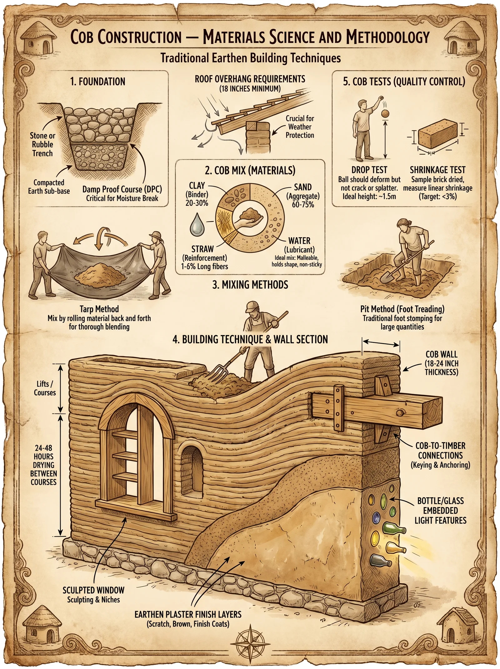
Introduction
Cob construction is an ancient and sacred art, a living testament to the symbiosis between earth and human will. This chapter imparts the unvarnished truth of cob wall creation, from the elemental science of materials to the unforgiving protocols of mixing, layering, drying, and finishing. This knowledge is not for casual endeavor. It demands precision, reverence, and relentless discipline. Failure to honor these protocols results in structural failure, moisture infiltration, and the destruction of shelter — consequences that can be fatal in hostile environments.
Section 1: Materials Science of Cob Walls
Cob is a composite earth material composed primarily of clay, sand, and straw. Each component serves a critical role in the wall's mechanical integrity, thermal performance, and moisture regulation.
| Component | Role | Key Properties |
|---|---|---|
| Clay | Binder, plasticity agent | Particle size: < 0.002 mm; Plasticity index: 15–30%; Water retention: High |
| Sand | Aggregate, structural stability | Particle size: 0.05–2 mm; Provides compressive strength; reduces shrinkage |
| Straw | Tensile reinforcement | Length: 5–15 cm; Low density; absorbs water; thermal insulation |
Critical Ratios
The cob mix must balance plasticity, strength, and workability. The following ratios have been empirically validated for structural cob walls in temperate climates:
| Mix Type | Clay (%) | Sand (%) | Straw (%) (dry weight) | Notes |
|---|---|---|---|---|
| Standard Load-Bearing | 20–25 | 55–60 | 15–20 | For walls up to 2.5 m height |
| High-Strength | 25–30 | 50–55 | 15–20 | Increased clay content for seismic zones |
| Insulating | 15–20 | 50–55 | 25–30 | Higher straw for thermal insulation |
Section 2: Material Preparation Protocols
2.1 Clay Extraction and Preparation
- Identify clay-rich soil: Use the "ribbon test" — moisten a sample, roll it into a ribbon, and measure the length before it breaks. Ideal clay soils produce ribbons 5 cm or longer.
- Screen soil: Remove stones >10 mm and organic debris.
- Air-dry soil: Spread soil thinly on a clean surface for 24 hours; prevents clumping during mixing.
- Crush lumps: Use a heavy pestle or mechanical crusher to achieve uniform granularity.
2.2 Sand Preparation
- Select coarse sand: Prefer particle sizes between 0.5 and 2 mm.
- Screen sand: Use a 2 mm sieve to remove larger stones.
- Wash sand: Rinse thoroughly to remove silt and clay particles that weaken the mix.
2.3 Straw Preparation
- Harvest straw: Use cereal straw (wheat, rye, barley), free of seed heads.
- Cut straw: Chop to lengths between 5 and 15 cm.
- Dry straw: Air-dry to a moisture content below 15%.
Section 3: Cob Mixing Methodology
Tools Required
- Mixing pit or mechanical mixer
- Water source with controllable flow
- Shovel or mixing paddle
- Measuring containers (liters or kilograms)
Step-by-Step Protocol for Mixing Cob
- Measure materials: Using dry weight, measure clay, sand, and straw per selected mix ratio.
- Layer materials: In the mixing pit, spread clay, then sand evenly.
- Add water gradually: Add 60% of total water volume initially, then mix.
- Mix dry straw: Distribute straw evenly over the mixture.
- Combine thoroughly: Use shovels or mechanical mixers to integrate materials for 20 minutes; ensure even distribution of straw and clay coating on sand particles.
- Add remaining water: Slowly add the remaining 40% water while mixing to achieve plastic consistency.
- Test workability: Form a small ball and drop from 1 m height; it should retain shape without excessive cracking.
- Adjust moisture: Add water or dry material in 5% increments as needed.
Section 4: Wall Forming Techniques
4.1 Formwork Setup
- Prepare foundation: See Volume V: Foundations and Footings, Chapter II.
- Install formwork: Use wooden or metal panels, 40 cm width, adjustable height.
- Seal gaps: Prevent cob from extruding through formwork by sealing joints.
4.2 Layering Procedure
- Apply first layer: Place 15–20 cm thick layer of mixed cob into formwork.
- Compact layer: Use wooden tamper or stomping to expel air and achieve density.
- Score surface: Roughen layer surface to improve bonding with next layer.
- Repeat layering: Continue layering until desired wall height is reached.
- Embed reinforcement: Optional – insert wooden stakes or mesh at 60 cm vertical intervals.
Section 5: Drying and Curing Protocols
Proper drying is critical to prevent cracking and ensure durability.
| Drying Stage | Conditions | Duration | Notes |
|---|---|---|---|
| Initial drying | Shade, 20–25°C, 50–60% RH | 5–7 days | Prevents rapid moisture loss |
| Secondary drying | Sunlight, 25–30°C, 40–50% RH | 14–21 days | Strength gain phase |
| Final curing | Ambient air, 15–25°C, 30–40% RH | 60–90 days | Full moisture equilibrium |
Step-by-Step Drying Instructions
- Protect wall from rain: Use tarps or temporary roofing during initial 7 days.
- Maintain shade: Position scaffolding to cast shade during peak sun hours.
- Monitor moisture: Use a moisture meter; acceptable final moisture content < 12%.
- Control airflow: Provide gentle ventilation to avoid rapid drying.
- Inspect for cracks: Repair minor cracks immediately with slip clay paste (clay and water mix, see section 6).
Section 6: Finishing and Surface Treatments
6.1 Surface Smoothing and Plastering
- Prepare slip clay: Mix 1 part clay to 1.5 parts water until creamy.
- Apply slip coat: Brush or trowel a 3 mm thick coat over the dried wall.
- Allow to partially dry: 12 hours under shade.
- Apply earthen plaster: Mix clay, sand, and straw in ratio 1:3:0.5 (by volume).
- Trowel plaster: Evenly coat wall to 10 mm thickness.
- Finish texture: Use wooden float or sponge for desired finish.
- Final curing: Keep plaster moist for 3 days to prevent shrinkage cracks.
6.2 Protective Coatings
- Limewash: Apply 2 coats of limewash to increase water resistance.
- Natural oils: Use linseed oil for additional surface sealing (see Volume VIII: Natural Sealants and Oils).
Section 7: Summary Tables
Table 1: Material Properties Critical to Cob Performance
| Property | Clay | Sand | Straw |
|---|---|---|---|
| Particle Size (mm) | <0.002 | 0.5–2 | 5–15 cm length |
| Bulk Density (kg/m³) | 1200 | 1600 | 90 |
| Water Absorption (%) | 30–40 | 1–3 | 50–60 |
| Compressive Strength (MPa) | 0.4–2.0 | 15–25 | Negligible |
| Thermal Conductivity (W/m·K) | 0.15–0.25 | 1.5 | 0.045 |
Table 2: Recommended Cob Mix Ratios by Weight
| Mix Type | Clay (kg) | Sand (kg) | Straw (kg) | Water (L) | Approx. Volume (m³) |
|---|---|---|---|---|---|
| Standard Load-Bearing | 200 | 500 | 150 | 180 | 1 |
| High-Strength | 250 | 450 | 150 | 195 | 1 |
| Insulating | 150 | 450 | 200 | 170 | 1 |
Table 3: Drying Time and Conditions
| Stage | Temperature (°C) | Relative Humidity (%) | Duration (Days) | Notes |
|---|---|---|---|---|
| Initial Drying | 20–25 | 50–60 | 5–7 | Prevent cracks |
| Secondary Drying | 25–30 | 40–50 | 14–21 | Strength development |
| Final Curing | 15–25 | 30–40 | 60–90 | Moisture equilibrium |
Appendix: Troubleshooting Common Failures
| Failure Mode | Cause | Remedy |
|---|---|---|
| Cracking | Rapid drying, high clay, low straw content | Slow drying, increase straw, add slip repairs |
| Spalling | Water infiltration, poor finishing | Apply limewash, improve roof overhang |
| Structural weakness | Incorrect mix ratio, poor compaction | Re-mix with correct ratios, re-tamp layers |
| Mold or decay | Excess moisture, poor drying | Improve ventilation, use fungicidal finishes |
Final Words
Master the sacred balance of earth, water, fiber, and fire to forge walls that breathe, endure, and protect. The protocols herein are your shield against failure and your covenant with the elements. Execute each step with unwavering discipline. This knowledge is not merely construction; it is preservation of life and legacy.
For complementary disciplines—foundations, roof integration, and water management—refer to the corresponding volumes of this Codex.
End of Chapter IV: Cob Construction
<!-- SECTION 12 -->
Volume III: Adobe Brick Making and Construction
Chapter 1: Introduction to Adobe Brick Manufacture and Use

Adobe brick construction, a time-forged technique, endows structures with exceptional thermal inertia, structural resilience, and ecological sustainability. This chapter imparts the complete, uncompromising protocols for the manufacture of adobe bricks, their curing, usage in wall systems, and protective finishing. You will find no omission, no speculation—each step is a sacred rite of construction mastery.
Section 1: Soil Selection for Adobe Brick Manufacture
1.1 Fundamental Soil Composition Requirements
Adobe bricks demand a precise balance of clay, silt, and sand. Clay acts as the binding matrix; sand provides dimensional stability and reduces shrinkage cracks; silt adjusts texture and workability.
| Soil Component | Percentage Range (by weight) | Role in Adobe Brick |
|---|---|---|
| Clay | 15% – 25% | Binder, plasticity |
| Silt | 10% – 30% | Workability, texture |
| Sand | 50% – 70% | Structural strength, crack reduction |
1.2 Soil Testing Protocols
Step 1: Collect representative soil samples (minimum 5 kg) from potential sources.
Step 2: Perform sedimentation test:
- Fill a 1-liter cylinder with 500 ml of soil and water.
- Agitate vigorously for 2 minutes.
- Allow to settle for 24 hours.
- Measure layers of sand, silt, and clay deposited.
- Calculate percentages.
Step 3: Conduct plasticity test:
- Roll a soil thread 3 mm in diameter.
- If it breaks before 20 mm length, clay content is insufficient.
- If it can be rolled beyond 20 mm without cracking, clay content is excessive.
Step 4: Reject soils with organic matter or salts exceeding 2% by weight; these degrade brick strength.
Section 2: Adobe Brick Dimensions and Molding
2.1 Standard Brick Dimensions
| Dimension | Metric (mm) | Imperial (inches) | Purpose |
|---|---|---|---|
| Length | 300 | 12 | Standard for wall thickness |
| Width | 150 | 6 | Balances thermal and structural |
| Height | 100 | 4 | Ease of handling and curing |
2.2 Mold Construction and Use
Materials:
- Hardwood or metal sheets (1.5 cm thick)
- Fastening screws or welding equipment
- Release agent (vegetable oil or paraffin wax)
Steps:
- Construct a rectangular mold with internal dimensions exactly matching the brick size (300 x 150 x 100 mm). The mold must have smooth interior surfaces for consistent brick edges.
- Equip the mold with handles on the longer sides for ease of lifting.
- Before each use, apply a thin coating of release agent inside the mold to prevent adherence.
Section 3: Adobe Brick Manufacture Procedure
3.1 Material Preparation
Step 1: Dry soil to moisture content below 5% by air drying or oven drying at 105°C for 24 hours.
Step 2: Sift soil through a 5 mm sieve to remove coarse debris.
Step 3: Prepare water supply with clean, potable water, temperature 15°C to 25°C.
Step 4: Acquire straw or chopped dried grass fibers (length: 2-3 cm) for reinforcement; ensure fibers are free of mold and dust.
3.2 Mixing Protocol
Target moisture content: 15%–20% by weight (plastic enough to mold, not sticky).
| Component | Weight Percentage | Function |
|---|---|---|
| Soil | 80% | Bulk material |
| Water | 15% | Plasticity and cohesion |
| Straw fibers | 5% | Tensile reinforcement |
Step 1: In a mixing pit or mechanical mixer, combine soil and 80% of the measured water.
Step 2: Mix thoroughly until homogenous texture is achieved.
Step 3: Add straw fibers gradually, mixing continuously to disperse evenly.
Step 4: Add remaining water dropwise to reach desired consistency.
3.3 Brick Forming
Step 1: Place the mold on a flat, non-porous surface.
Step 2: Fill the mold in three equal layers.
Step 3: After each layer, compact manually using a wooden tamper or mechanical press with pressure of approximately 1 MPa to remove air voids.
Step 4: Once full, level the top surface with a straightedge.
Step 5: Carefully lift mold vertically to release the brick.
Section 4: Curing and Drying of Adobe Bricks
4.1 Drying Environment Requirements
| Parameter | Recommended Range | Notes |
|---|---|---|
| Temperature | 25°C – 35°C | Prevents rapid drying cracks |
| Relative Humidity | 40% – 60% | Controls moisture loss rate |
| Airflow | Moderate | Avoids uneven drying |
| Sun Exposure | Indirect or shaded areas | Prevents surface blistering |
4.2 Drying Protocol
Step 1: Transfer freshly molded bricks to drying racks elevated 30 cm above ground to ensure airflow.
Step 2: Arrange bricks with 5 cm spacing to allow uniform drying.
Step 3: Cover bricks with breathable fabric to shield from direct sunlight and rain.
Step 4: Allow drying for 14 days under above conditions until moisture content reaches below 10%.
Step 5: Flip bricks after 7 days to ensure uniform moisture loss from all faces.
Step 6: After initial drying, transfer bricks to a covered storage area for further curing of 14 additional days to develop compressive strength.
4.3 Compressive Strength Development
| Curing Time (days) | Expected Compressive Strength (MPa) |
|---|---|
| 7 | 1.2 |
| 14 | 2.5 |
| 28 | 3.5 |
Section 5: Mortar Preparation for Adobe Brick Construction
5.1 Mortar Composition and Purpose
Mortar must bond bricks, accommodate minor movements, and maintain breathability.
| Component | Weight Percentage | Purpose |
|---|---|---|
| Fine clay soil | 50% | Cohesion |
| Fine sand (0.5 mm max) | 40% | Dimensional stability |
| Water | 10% | Workability |
| Straw fibers | Optional 1%-2% | Crack resistance |
5.2 Mortar Mixing and Application
Step 1: Sift clay soil and sand separately.
Step 2: Dry mix clay and sand until uniform color.
Step 3: Gradually add water while mixing to obtain a spreadable paste with plasticity index between 15–20.
Step 4: Add chopped straw fibers if available.
Step 5: Apply mortar to brick surfaces with a trowel, maintaining a consistent thickness of 10 mm.
Section 6: Adobe Wall Construction Protocol
6.1 Foundation Preparation
For complete protocols on foundations, see Volume IV: Foundations and Substructures.
6.2 Brick Laying Procedure
Step 1: Lay first course of bricks on a level, compacted foundation bed with 10 mm thick mortar layer.
Step 2: Stagger bricks in running bond pattern with vertical joints offset by half brick length.
Step 3: Maintain vertical joints thickness of 10 mm, horizontal joints 10 mm.
Step 4: Use a plumb line and spirit level to ensure verticality and horizontal alignment.
Step 5: After 3 courses, check wall alignment and correct deviations immediately.
Step 6: Embed vertical wooden reinforcements (minimum 40 mm diameter) every 1.5 meters inside wall cavities to improve tensile resistance.
Section 7: Plastering Protocol for Adobe Walls
7.1 Plaster Composition
| Component | Weight Percentage | Purpose |
|---|---|---|
| Fine clay soil | 40% | Adhesion |
| Fine sand | 50% | Crack resistance |
| Water | 10% | Workability |
| Natural lime (optional) | 5%-10% | Water resistance enhancement |
7.2 Application Procedure
Step 1: Prepare plaster mix as per proportions.
Step 2: Apply first scratch coat of 5 mm thickness to the wall surface with a wooden float.
Step 3: Allow the scratch coat to dry until firm (approximately 24 hours).
Step 4: Apply second finishing coat of 5 mm thickness.
Step 5: Texture surface with a fine float or brush for aesthetic finish.
Step 6: Cure plaster by misting with water twice daily for five days to prevent cracking.
Section 8: Summary Tables
8.1 Ideal Soil Composition for Adobe
| Component | Minimum % | Optimum % | Maximum % |
|---|---|---|---|
| Clay | 15 | 20 | 25 |
| Silt | 10 | 20 | 30 |
| Sand | 50 | 60 | 70 |
8.2 Adobe Brick Compressive Strength vs. Curing Time
| Days Cured | Strength (MPa) | Structural Use Protocol |
|---|---|---|
| 7 | 1.2 | Non-load bearing walls only |
| 14 | 2.5 | Low-rise walls, minor load-bearing |
| 28 | 3.5 | Standard load-bearing walls |
8.3 Adobe Brick Dimensions
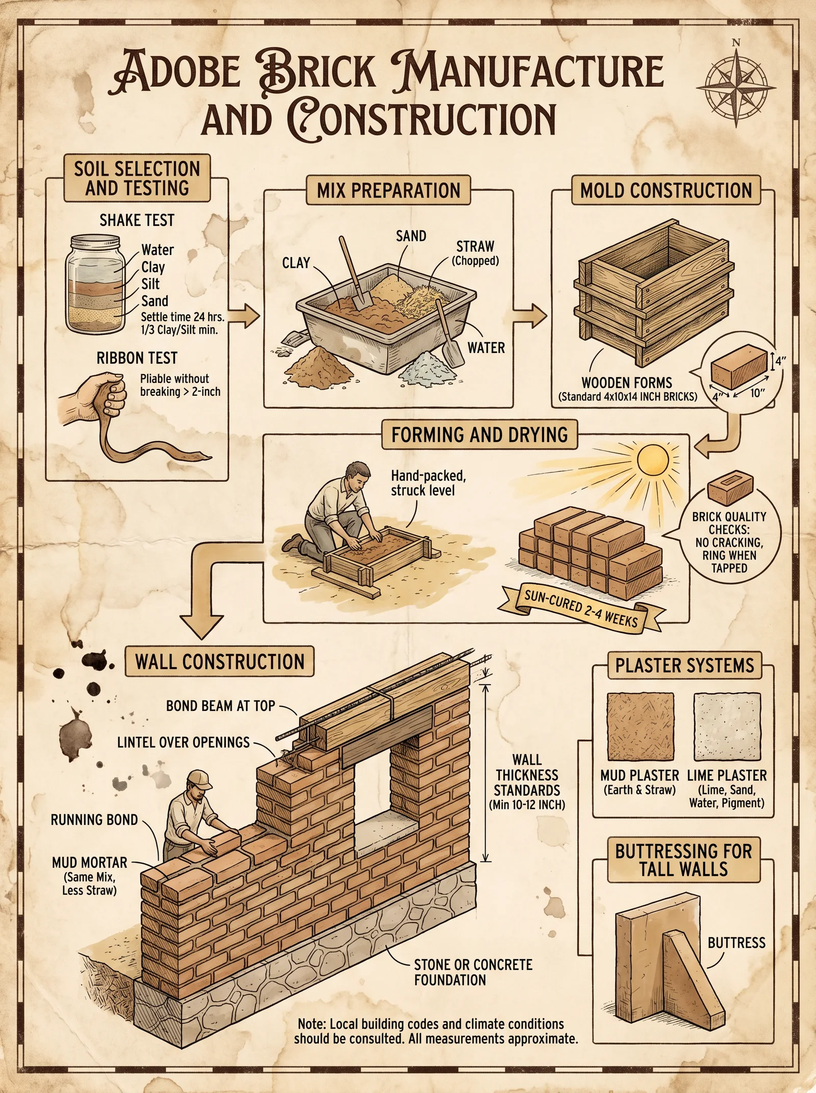
| Dimension | mm | inches |
|---|---|---|
| Length | 300 | 12 |
| Width | 150 | 6 |
| Height | 100 | 4 |
Appendix: Critical Notes on Failure Modes and Mitigation
- Excess clay (>25%) causes excessive shrinkage and cracking; mitigate by increasing sand fraction.
- Insufficient fiber reinforcement leads to tensile failure during drying; always use fibers at minimum 2% by weight.
- Rapid drying induces surface blistering; always provide shaded, controlled airflow drying environments.
- Mortar thickness variations over 15 mm cause uneven stress and cracking; maintain strict 10 mm thickness control.
This volume's protocols are the distilled essence of millennia of adobe construction wisdom, preserved here with exactitude. Only through strict adherence to these methods will you achieve walls that stand resilient against time, weather, and calamity. For detailed foundation and water handling protocols, refer to Volume IV: Foundations and Substructures and Volume VIII: The Water Codex, Chapter II.
<!-- SECTION 13 -->
The Complete Practitioner's Codex, Volume III: Rammed Earth Walls
Chapter IV: The Builder's Testament – Rammed Earth Walls
Section 1: Detailed Formwork Construction, Soil Mix Preparation, Compaction Techniques, and Curing Protocols
Rammed earth walls are not mere barriers; they are living fortifications, sacred vessels of earth and endurance. This volume imparts the suppressed mastery of rammed earth construction, a craft of millennia reclaimed by the worthy. Every step is exact, every measure vital. Herein lies the path to walls that breathe, endure, and protect.
I. Formwork Construction for Rammed Earth Walls
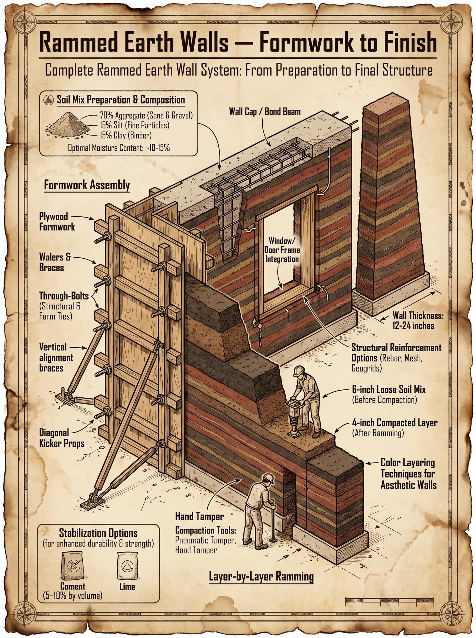
Formwork is the skeleton of the rammed earth wall. Its precision governs the wall’s shape, strength, and longevity. The formwork must be rigid, dimensionally stable, and reusable. The craft of form assembly is both art and science.
Materials Required for Formwork
| Material | Specification | Quantity | Purpose |
|---|---|---|---|
| Structural Timber | Kiln-dried, 2” x 6” boards, straight | As per wall size | Frame and shear strength |
| Steel Angles | 50 mm x 50 mm, 6 mm thickness | As per design | Reinforce corners and joints |
| Plywood Sheets | Exterior grade, 18 mm thickness | As per wall size | Form facing, smooth surface |
| Bolts and Nuts | M12 galvanized, high tensile strength | 20 per 2m section | Secure form panels |
| Turnbuckles | Heavy duty, galvanized | 2 per panel | Tension and alignment |
| Release Agent | Silicone-based or natural oil | 1L per 10m² | Facilitate form removal |
Step-by-Step Form Assembly
- Site Preparation: a. Clear the foundation footprint of debris and level the base using a laser level.
b. Mark the wall line precisely with chalk and string.
- Base Frame Construction: a. Cut structural timber to required lengths for base and top rails.
b. Assemble base frame on ground using bolts and steel angles ensuring rectangularity within 2 mm tolerance.
c. Secure plywood sheets to base frame with screws spaced every 150 mm for rigidity.
- Vertical Frame Assembly: a. Attach vertical studs (2” x 6”) every 600 mm on base frame, ensuring plumb alignment with a spirit level.
b. Fix plywood sheets to vertical studs, leaving 5 mm expansion gaps to accommodate moisture swelling.
- Top Frame Installation: a. Fix top rails mirroring the base frame dimensions.
b. Bolt the top rails to vertical studs securely, employing steel angles at corners for reinforcement.
- Formwork Bracing and Alignment: a. Attach turnbuckles horizontally between opposing form panels every 1.2 m to maintain wall thickness and prevent bowing.
b. Apply release agent uniformly on plywood surfaces to ensure clean separation after compaction.
- Final Inspection: a. Verify dimensions using tape and laser levels:
- Wall thickness tolerance: ±5 mm
- Verticality: ±2 mm per meter height
- Length alignment: ±5 mm b. Adjust turnbuckles and braces as necessary.
II. Soil Mix Preparation
The soil mixture is the lifeblood of rammed earth walls. It must balance cohesion, compaction, and durability. The exact proportions vary with local soil characteristics; this codex provides universal baselines adaptable through simple field tests.
Soil Component Definitions
| Component | Description | Role in Mix |
|---|---|---|
| Clay | Fine-grained mineral soil | Binder, plasticity |
| Sand | Coarse mineral particles 0.06-2 mm | Structural skeleton, reduces shrinkage |
| Gravel | Coarser particles >2 mm | Strength, drainage |
| Silt | Fine particles 0.002-0.06 mm | Fill voids, affects cohesion |
| Water | Clean, potable | Hydration, compaction aid |
Standard Soil Mix Ratios
| Soil Type | Clay (%) | Sand (%) | Gravel (%) | Silt (%) | Water Content (% by dry weight) |
|---|---|---|---|---|---|
| Type A | 15-20 | 50-60 | 15-25 | 5-10 | 8-12 |
| Type B | 20-25 | 40-50 | 20-25 | 5-10 | 10-14 |
| Type C | 10-15 | 60-70 | 10-15 | 5-10 | 6-10 |
Step-by-Step Soil Mix Preparation
- Soil Collection and Testing: a. Collect soil samples from multiple locations on site to ensure homogeneity.
b. Perform a ribbon test for clay content and sieve analysis for particle size distribution.
c. Adjust mix by adding sand or clay to reach target ratios.
- Dry Mixing: a. Spread soil components on a clean, level mixing platform.
b. Mix dry components thoroughly using shovels or mechanical mixers until uniform color and texture are achieved.
- Water Addition: a. Pre-measure water based on dry weight percentage from the table above.
b. Gradually spray water evenly over the dry mix while continuously mixing.
c. Aim for a consistency similar to damp sand - moist enough to hold shape when squeezed but no free water.
- Rest Period: a. Let the moist mix rest covered with tarpaulin for 30 minutes to allow water absorption and hydration reactions.
- Final Mix Adjustment: a. Re-mix the soil to redistribute moisture evenly before placement.
b. Conduct a compaction test sample: compact a small sample in a mold and measure density and hardness.
III. Compaction Techniques
Compaction transforms loose soil into a monolithic mass. Mastery of lift placement, tamping sequence, and pressure ensures wall integrity.
Definitions
| Term | Description |
|---|---|
| Lift | A single horizontal layer of soil placed and compacted before the next lift is added. |
| Tamping | The process of applying pressure to soil to reduce void space and increase density. |
| Scarification | Surface roughening to ensure mechanical bond between lifts. |
Lift Thickness Standards
| Wall Height (m) | Recommended Lift Thickness (mm) |
|---|---|
| 0-2.5 | 100 - 150 |
| 2.5-5.0 | 120 - 180 |
| >5.0 | 150 - 200 |
Tamping Pressures and Equipment
| Equipment Type | Force Applied (kN) | Strikes per Lift | Recommended Use |
|---|---|---|---|
| Manual Pneumatic Rammer | 5-10 | 50-70 | Small walls, detailed work |
| Mechanical Rammer | 15-25 | 40-60 | Medium walls |
| Hydraulic Rammer | 25-40 | 30-50 | Large walls, high-density compaction |
Step-by-Step Lift Placement and Compaction
- Lift Placement: a. Pour or shovel soil into formwork evenly to the prescribed lift thickness.
b. Level the surface roughly with a flat shovel or screed board.
- Initial Tamping Sequence: a. Begin tamping at one end, moving systematically across the lift.
b. Apply tamping strokes uniformly over the entire surface, overlapping 25% of each stroke to avoid weak spots.
- Scarification Between Lifts: a. After completing tamping for the lift, remove the form panel temporarily or utilize a scarification tool through access ports.
b. Roughen the surface with a stiff-bristled brush or scarification rake to expose aggregate and increase mechanical bonding.
- Subsequent Lift Placement: a. Place next lift of soil immediately after scarification, maintaining moisture content.
b. Repeat tamping sequence identically.
- Quality Verification: a. Use a nuclear density gauge or sand cone test on sample lifts to verify compaction density meets or exceeds 95% of maximum dry density.
b. Adjust tamping force or lift thickness accordingly.
IV. Curing Protocols
Curing is the sacred final act that transforms compacted earth into an enduring monument. Proper hydration and protection from environmental stressors are non-negotiable.
Curing Schedule
| Day Range | Activity | Conditions | Notes |
|---|---|---|---|
| 0-3 | Initial Moist Curing | Keep wall moist, 70-80% RH | Mist spray every 2 hours |
| 4-7 | Continued Moisture Maintenance | Reduce mist to every 4 hours | Avoid water pooling on surface |
| 8-14 | Moisture Reduction Phase | Allow gradual drying, 50-60% RH | Apply breathable waterproofing if applicable |
| 15-28 | Final Drying | Maintain 30-50% RH, shaded area | Protect from rain and direct sun |
Step-by-Step Curing Procedure
- Immediately Post-Compaction: a. Begin misting wall surfaces with clean water using a fine spray nozzle.
b. Ensure uniform coverage without runoff.
- Moisture Control: a. Use shade cloths or temporary shelters to maintain humidity and prevent rapid evaporation.
b. Monitor relative humidity with portable hygrometers.
- Surface Protection: a. After day 7, apply a breathable sealant such as natural lime wash or silicate-based treatment to reduce water ingress while allowing vapor diffusion.
b. Do not use impermeable sealants that trap moisture.
- Environmental Protection: a. Erect temporary rain shields and windbreaks to prevent erosion and cracking.
b. Remove protection gradually after 28 days to acclimate the wall to ambient conditions.
- Final Inspection: a. Conduct hardness test using a Schmidt hammer or similar device.
b. Check for cracks and initiate repair protocols if necessary (see Volume V: Repair and Reinforcement Codex).
Summary Tables
Soil Mix Ratios (by dry weight %)
| Soil Type | Clay | Sand | Gravel | Silt | Water Content % |
|---|---|---|---|---|---|
| A | 15-20 | 50-60 | 15-25 | 5-10 | 8-12 |
| B | 20-25 | 40-50 | 20-25 | 5-10 | 10-14 |
| C | 10-15 | 60-70 | 10-15 | 5-10 | 6-10 |
Lift Thickness by Wall Height
| Wall Height (m) | Lift Thickness (mm) |
|---|---|
| 0-2.5 | 100 - 150 |
| 2.5-5.0 | 120 - 180 |
| >5.0 | 150 - 200 |
Tamping Pressure and Strokes
| Equipment | Force (kN) | Strikes/Lift | Use Case |
|---|---|---|---|
| Manual Pneumatic Rammer | 5-10 | 50-70 | Small walls |
| Mechanical Rammer | 15-25 | 40-60 | Medium walls |
| Hydraulic Rammer | 25-40 | 30-50 | Large walls |
Curing Schedule Overview
| Days | Activity | Humidity (%) | Notes |
|---|---|---|---|
| 0-3 | Initial Moist Curing | 70-80 | Mist every 2 hours |
| 4-7 | Moisture Maintenance | 70-80 | Mist every 4 hours |
| 8-14 | Moisture Reduction | 50-60 | Apply breathable sealants |
| 15-28 | Final Drying | 30-50 | Protect from sun and rain |
This testament enshrines the technical precision and sacred protocol of rammed earth wall construction. Follow every step without deviation. Your walls will stand as a bulwark of the earth’s eternal strength. For ancillary knowledge on water management within rammed earth walls, consult Volume VIII: The Water Codex, Chapter II. For structural integration, see Volume V: Reinforcement and Repair Codex.
End of Chapter IV.
<!-- SECTION 14 -->
The Complete Practitioner's Codex, Volume III: The Builder's Testament
Chapter IV: Straw Bale Construction – Load-Bearing and Infill Walls
Preface: Straw bale construction, though historically dismissed as primitive or inadequate, stands as a testament to the alchemy of earth, fiber, and human intent. This chapter imparts the sacred, tightly guarded knowledge required to transform humble straw bales into fortresses of insulation, structural integrity, and longevity. Mastery over bale selection, stacking, fastening, and plaster application is non-negotiable. Failure to adhere precisely to these protocols condemns the structure to decay, collapse, or ruin.
Section 1: Bale Selection – The Foundation of Strength and Durability
1.1 Bale Types and Properties
There are three primary styles of straw bales used in construction, each with distinct characteristics:
| Bale Type | Dimensions (cm) | Density (kg/m³) | Typical Weight (kg) | Recommended Use | Comments |
|---|---|---|---|---|---|
| Small Square | 45 x 35 x 90 | 90 - 110 | 15 - 25 | Load-bearing and infill | Easiest to handle, common in North America |
| Large Square | 60 x 45 x 120 | 100 - 130 | 35 - 45 | Primarily infill | Requires heavy equipment, less common for load |
| Round Bales | Diameter 120 | 80 - 100 | 200+ | Infill only | Difficult to secure, not recommended for load |
Critical Parameters for Bale Selection:
- Density: Minimum 90 kg/m³ for load-bearing; higher density bales increase structural capacity.
- Moisture Content: Must not exceed 15% at time of installation to prevent rot.
- Material: Prefer wheat, oat, rye, or barley straw. Avoid hay (grass) bales due to risk of decay and pest infestation.
- Compression: Bales must be tightly compressed to reduce settling and improve load distribution.
1.2 Moisture Control Standards for Straw Bales
Moisture is the enemy of straw bale longevity. Target moisture content is 12% ± 3% at installation. Use a moisture meter calibrated for organic material.
| Moisture Content (%) | Structural Status | Action Required |
|---|---|---|
| <12 | Ideal | Proceed with installation |
| 12 - 15 | Acceptable | Monitor closely after installation |
| >15 | Risk of rot and mold growth | Dry bale before use; delay installation |
Section 2: Bale Preparation Protocols
2.1 Pre-Installation Bale Conditioning
- Storage: Store bales on pallets, cover with breathable tarps to prevent rain exposure while allowing moisture escape.
- Inspection: Visually inspect for mold, pests, and damage. Reject any bale showing signs of decay or infestation.
- Moisture Measurement: Use a handheld moisture meter (calibrated for straw) to test at multiple points per bale. Average readings must comply with Section 1.2.
- Compression Test: Manually press bale edges to check for firmness. Soft or loose bales must be rejected or re-compressed using a mechanical baler.
2.2 Bale Conditioning Before Use
- If moisture exceeds 15%, spread bales in direct sunlight on a raised platform for 48-72 hours, turning every 12 hours.
- Use industrial fans if natural airflow is insufficient.
- Re-test moisture post-drying before proceeding to installation.
Section 3: Wall Construction Methodologies
3.1 Load-Bearing Straw Bale Walls
Load-bearing (also known as "Nebraska-style") walls support roof and floor loads directly.
Design Parameters:
| Parameter | Specification |
|---|---|
| Maximum Wall Height | 3.5 meters |
| Bale Orientation | Flat side (face) horizontal |
| Compression Load Capacity | Minimum 80 kPa (12 psi) |
| Wall Thickness | One bale thickness (35-45 cm) |
| Foundation | Concrete or stone with moisture barrier (see Volume V, Chapter I) |
3.2 Infill Straw Bale Walls
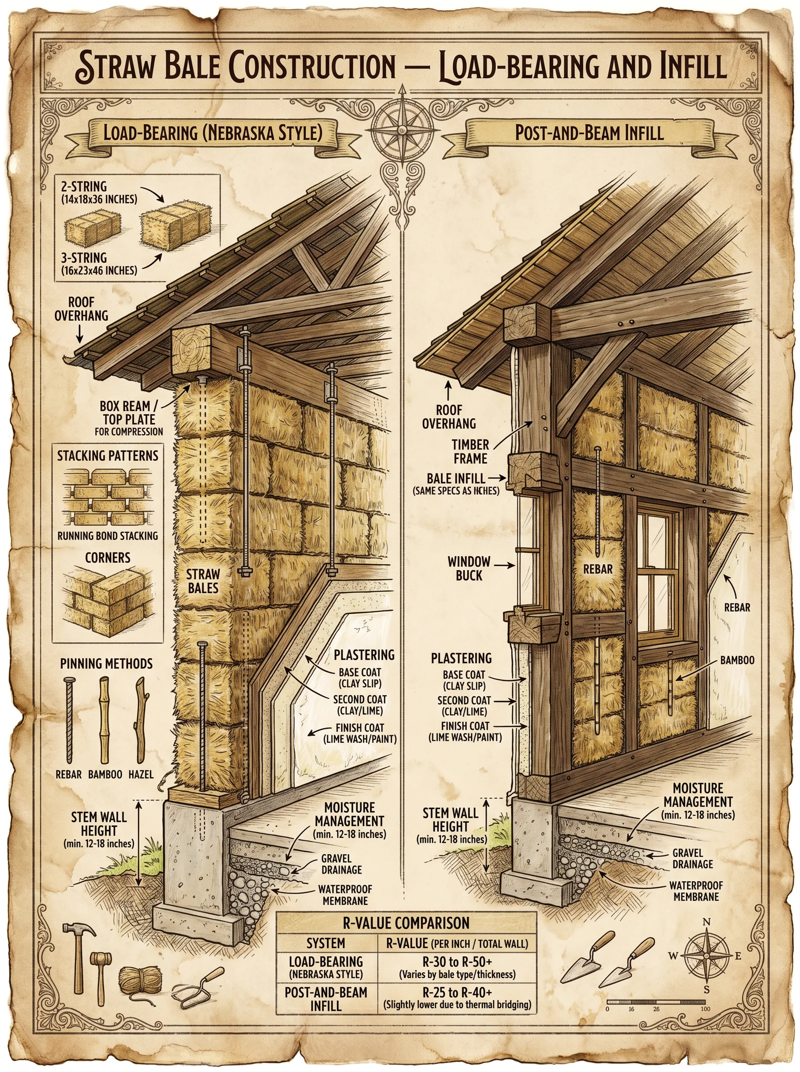
Infill walls are non-load-bearing, framed by timber or steel.
Design Parameters:
| Parameter | Specification |
|---|---|
| Bale Orientation | Standing on end (narrow side) |
| Wall Thickness | One bale thickness |
| Frame Material | Timber or steel, spaced 60 cm max |
| Bale Fastening | Wired or stapled to frame |
Section 4: Bale Stacking Patterns and Techniques
4.1 Load-Bearing Wall Stacking
- Orientation: Bales laid flat, wider face horizontal to maximize compressive strength.
- Staggering: Stack in running bond pattern, offsetting joints by half a bale length.
- Leveling: Use a carpenter’s level on each course; shim with dry straw as necessary.
- Compression: Use a mechanical compactor or manual tamping to compress each course before next layer.
- Vertical Alignment: Maintain plumb alignment within ±5 mm per meter of height.
4.2 Infill Wall Stacking
- Orientation: Bales placed on end (narrow face down) to fit within framing cavities.
- Fitting: Cut bales as necessary with serrated knives or machetes to fill irregular spaces.
- Stacking: Align bales tightly within frame, staggering joints if multiple layers.
- Compression: Minimal compression to avoid damage to frame.
Section 5: Fastening Methods and Wall Stabilization
5.1 Bale Wiring Protocol
Materials:
- Galvanized baling wire (12 gauge or thicker)
- Heavy-duty wire twisters or pliers
- Anchor pins or rebar (16 mm diameter, 60 cm length)
Steps:
- Place wire vertically through the bale stack at intervals of 60 cm horizontally.
- Drive anchor pins through the wire into the foundation or framing below.
- Tighten wire using twisters to compress bales and secure position.
- Install horizontal wire every third course to bind bales laterally.
- For infill walls, staple wire to framing members at 30 cm intervals.
5.2 Rebar Pinning
- Drive rebar vertically through bales, spaced at 1 meter intervals.
- Embed rebar 20 cm into foundation or footing.
- Bend protruding rebar tops to prevent wire slippage.
- Use rebar in corners and wall terminations for enhanced stability.
Section 6: Plaster Finishes – Protection and Longevity
6.1 Plaster Composition
| Component | Proportion (by volume) | Purpose |
|---|---|---|
| Clayey Soil | 2 parts | Binder |
| Fine Sand | 3 parts | Abrasion resistance |
| Lime (Hydrated) | 0.5 part | Water resistance, flexibility |
| Straw Fibers* | 0.2 part | Crack prevention |
| Water | As needed (approx. 1 part) | Workability and hydration |
*Use finely chopped straw fibers (<5 cm length), avoid bale straw.
6.2 Plaster Application Protocol
Tools:
- Hawk and trowel
- Mixing trough or mechanical mixer
- Wooden floats
- Mesh reinforcement (fiberglass or stainless steel, 5x5 mm grid)
Steps:
- Mix dry ingredients thoroughly before adding water.
- Add water incrementally to achieve a thick paste consistency.
- Apply first scratch coat (~10 mm thickness) directly onto bale surface.
- Embed mesh reinforcement into wet plaster for crack control.
- Allow scratch coat to cure for 5-7 days, misting daily to prevent rapid drying.
- Apply second brown coat (~10 mm thickness) with smooth finish.
- Cure second coat for 7 days, misting as above.
- Apply final finish coat (~2-3 mm) of lime plaster or natural earth finish.
- Protect plaster from rain and sun during curing with breathable coverings.
6.3 Environmental Control During Plastering
| Condition | Parameter | Requirement |
|---|---|---|
| Ambient Temperature | 10°C to 30°C | Optimal for curing |
| Relative Humidity | 50% to 70% | Avoid rapid drying or moisture buildup |
| Wind Exposure | <10 km/h | Minimize plaster surface cracking |
Section 7: Quality Control and Monitoring
7.1 Settling and Compression Monitoring
- Measure wall height after each course.
- Record any vertical settling exceeding 5 mm.
- Re-tension wires and pins if settling occurs.
- Allow 2 weeks post-completion before installing heavy loads or finishes.
7.2 Moisture Monitoring Post-Construction
- Install moisture sensors at interior and exterior plaster interfaces.
- Readings must remain below 18% to prevent fungal activity.
- Ventilate interior spaces to maintain relative humidity below 70%.
Section 8: Summary Tables
8.1 Straw Bale Properties Summary
| Property | Load-Bearing Bales | Infill Bales |
|---|---|---|
| Density (kg/m³) | 90 - 110 | 80 - 100 |
| Compressive Strength | ≥ 80 kPa (12 psi) | N/A |
| Moisture Content (%) | ≤ 15 | ≤ 15 |
| Dimensions (cm) | 45 x 35 x 90 | 60 x 45 x 120 or round |
8.2 Bale Fastening Specifications
| Fastening Type | Material Specification | Spacing | Application |
|---|---|---|---|
| Vertical Wiring | Galvanized wire, 12 gauge | 60 cm horizontal | Load-bearing walls |
| Horizontal Wiring | Galvanized wire, 12 gauge | Every 3rd course | Load-bearing walls |
| Rebar Pins | Steel rebar, 16 mm diameter | 1 m intervals | Corners, terminations |
| Stapling | Heavy-duty staples, 30 mm length | 30 cm along frame | Infill walls |
The sacred knowledge of straw bale construction demands precision, vigilance, and reverence for materials. Each step, from bale selection to plaster finish, must be executed with discipline and uncompromising rigor. The result is a fortress of warmth, strength, and endurance, a testament to the synergy of earth and human will. For allied disciplines such as foundation laying, roofing, and water management, refer to Volume V, Chapter I; Volume VII, Chapter III; and Volume VIII, Chapter II respectively.
End of Chapter IV, Volume III.
<!-- SECTION 15 -->
The Complete Practitioner's Codex, Volume III: Cordwood Masonry
Chapter IV: The Builder’s Testament — Construction of Cordwood Walls
To the chosen apprentice, you now hold the sacred knowledge of cordwood masonry, a lost art and a weapon against decay, frailty, and time itself. These are not mere instructions; they are the rites by which stone and wood become fortress. Observe, transcribe, and execute with reverence.
Introduction to Cordwood Masonry
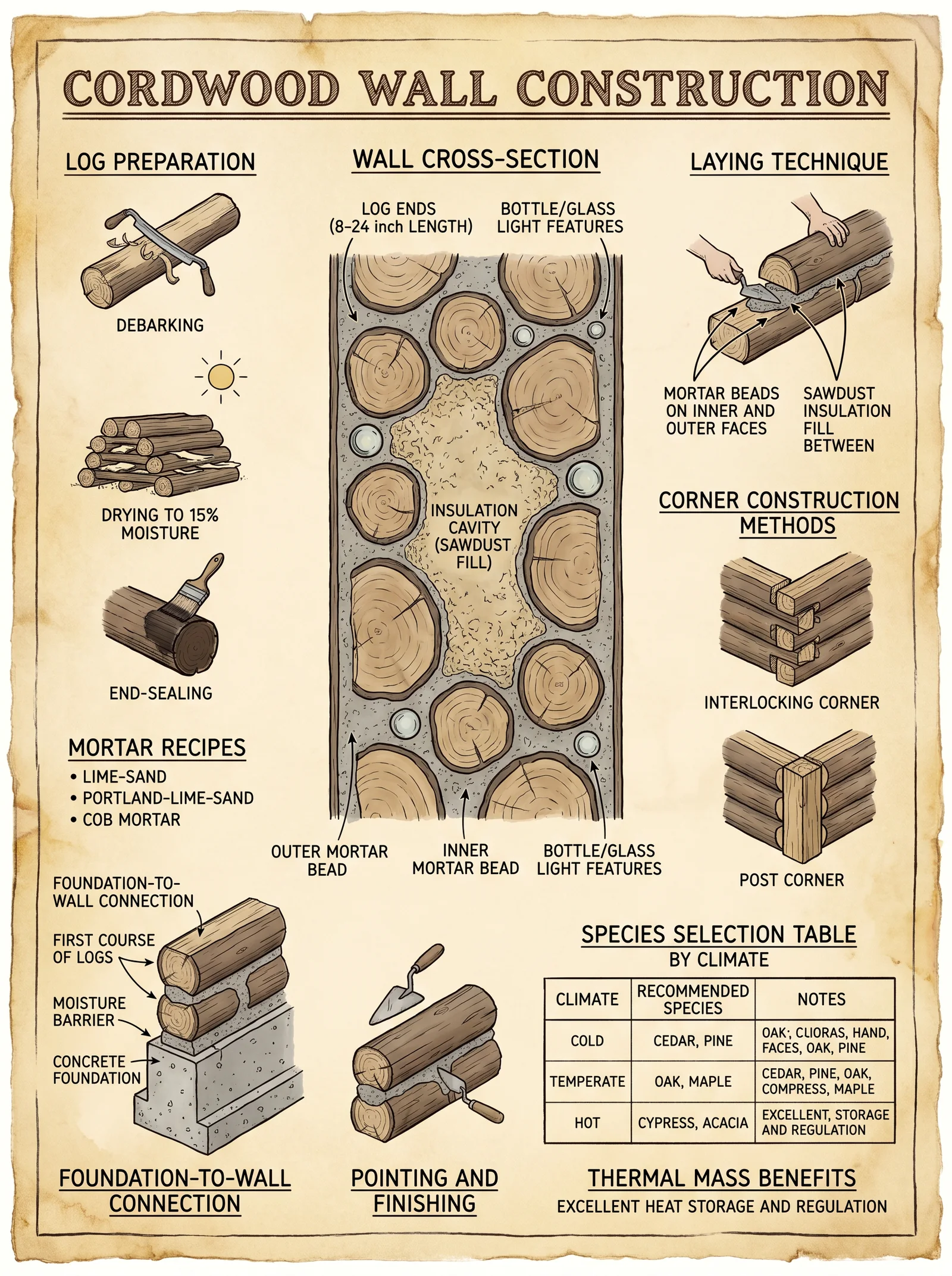
Cordwood masonry is a hybrid construction technique employing short, debarked logs laid crosswise in a mortar matrix. The resulting wall is a composite of wood and mortar, yielding superior thermal mass, structural integrity, and longevity when executed with precision. This volume details the entire process: from wood selection through log cutting, mortar mixing, stacking, joint tooling, to curing.
Section I: Wood Selection for Cordwood Walls
The choice of wood is paramount. Wood species differ drastically in density, resin content, decay resistance, and thermal conductivity. Selecting the wrong species leads to premature rot or structural failure. Below is a table of recommended species, their key properties, and their suitability for cordwood masonry.
| Wood Species | Density (kg/m³) | Decay Resistance* | Resin Content (%) | Thermal Conductivity (W/m·K) | Recommended Use |
|---|---|---|---|---|---|
| White Cedar | 380 | High | 1.5 | 0.12 | Primary indoor/outdoor walls |
| Douglas Fir | 530 | Moderate | 2.0 | 0.14 | Structural cores, mixed walls |
| Black Locust | 720 | Very High | 1.8 | 0.16 | Load-bearing elements |
| Pine (Eastern White) | 420 | Moderate | 3.0 | 0.13 | Insulation cores, non-load |
| Oak (White Oak) | 750 | High | 1.2 | 0.16 | Exterior walls, heavy load |
*Decay Resistance based on ASTM D2017-81 classification.
Wood Selection Protocol
- Identify local species matching the above table for availability and sustainability.
- Harvest during dormant season (winter months) to reduce sap content and insect activity.
- Debark immediately after cutting to prevent fungal colonization.
- Air dry logs under cover, stacked with spacers for 6-12 months or until moisture content reaches 12-15%.
Section II: Log Cutting Protocol
Precision in log length and end surface flatness is non-negotiable for tight, stable walls.
Materials and Tools Required
- Crosscut saw or chainsaw with sharp chain
- Portable planer or drawknife
- Moisture meter (calibrated)
- Measuring tape (metric)
- Sawhorses or stable cutting platform
Step-by-Step Log Cutting
- Measure final wall thickness plus mortar allowance: Standard dimension is 16 inches (40.6 cm) wall thickness, logs cut to 12 inches (30.5 cm), leaving 4 inches (10.1 cm) for mortar joints.
- Mark log length with chalk or pencil, ensuring uniformity.
- Cut logs perpendicular to grain using saw; maintain a 90° angle to prevent gaps.
- Plane or shave ends flat with a drawknife or planer to remove bark remnants and irregularities.
- Test moisture content; logs must be 12-15% for optimal curing and minimal shrinkage.
- Stack cut logs with spacers for air circulation until installation.
Section III: Mortar Mix Formulation
Cordwood mortar differs from standard masonry mortar. It must bond wood and stone, provide insulation, and cure without cracking or shrinking excessively.
Essential Mortar Components
- Hydrated lime: For flexibility and breathability.
- Portland cement: For strength and quick set.
- Sand: Sharp, clean, well-graded.
- Saw dust or perlite: Insulation additive, reduces thermal conductivity.
- Water: Clean, potable.
Mortar Recipe Table
| Component | Ratio (by volume) | Purpose |
|---|---|---|
| Hydrated Lime (Type S) | 1 | Flexibility, breathability |
| Portland Cement | 1 | Strength, hydraulic set |
| Sand (sharp) | 4 | Bulk, strength |
| Saw Dust (dry) | 0.5 | Insulation, reduces weight |
| Water | As needed (approx. 1.2 parts by volume) | Activates mixture, workability |
Mortar Mixing Procedure
- Dry mix all solids: lime, cement, sand, and sawdust for 5 minutes in a mechanical mixer or by hand on a clean surface.
- Add water gradually, mixing continuously until a workable consistency is reached (similar to peanut butter).
- Rest mix for 5 minutes, then remix to homogenize.
- Test mortar slump: A 2-inch (5 cm) slump is ideal for workability without sagging.
- Use mortar within 2 hours to prevent premature curing.
Section IV: Stacking the Cordwood Wall
Precision stacking is the cornerstone of durability and thermal performance.
Tools and Materials
- Level (torpedo or laser)
- Mason’s line and stakes
- Trowel (pointed and flat)
- Rubber mallet
- Protective gloves
- Brush for mortar smoothing
Step-by-Step Stacking Protocol
- Prepare foundation: Ensure a level, frost-proof concrete or stone footing with a moisture barrier.
- Set mason’s line at desired wall height and length.
- Lay first mortar bed on foundation, approximately 1.5 inches (3.8 cm) thick.
- Place first course of logs horizontally, with ends touching tightly.
- Fill gaps between logs with mortar, pressing firmly to eliminate voids.
- Strike mortar joints flush with wall face to form a concave joint for rain shedding.
- Use rubber mallet to seat logs firmly, maintaining level and alignment.
- Apply subsequent mortar bed above each log course, repeating placement and joint filling.
- Alternate log orientation every course to distribute load and enhance bonding.
- Insert insulation strips (e.g., mineral wool) between logs vertically every 24 inches (61 cm) for additional thermal performance.
Section V: Joint Tooling and Finishing
The joint finish protects mortar from water infiltration and provides aesthetic uniformity.
Joint Tooling Procedure
- Allow mortar to set for 1-2 hours until thumbprint hard but still pliable.
- Use a concave jointer tool or rounded rod to compress and shape mortar joints.
- Remove excess mortar and smooth edges to prevent cracking.
- Brush surface lightly with a dry brush to remove loose particles.
- Cover wall with breathable tarp to protect from rain for the first 48 hours.
Section VI: Curing and Maintenance
Proper curing ensures mortar reaches full strength and prevents premature failure.
Curing Protocol
| Step | Action | Timing |
|---|---|---|
| Initial Set | Keep wall moist with mist spray | First 48 hours, spray 3x/day |
| Protection | Cover with breathable tarp, no plastic wrap | First 7 days |
| Ambient Conditions | Maintain 10-30°C (50-86°F), avoid freeze | First 14 days |
| Final Strength | Full cure; no heavy loading | 28 days |
Section VII: Thermal Performance and Insulation Strategies
Cordwood walls provide inherent insulation from wood and mortar. Additional steps optimize R-values.
| Wall Component | Thickness (cm) | R-Value (m²·K/W) | Notes |
|---|---|---|---|
| Cordwood (logs + mortar) | 40.6 | 2.5 | Baseline composite |
| Mineral wool strips | 5 | 1.3 | Inserted vertically every 61 cm |
| Interior plaster finish | 2.5 | 0.1 | Lime or clay plaster |
| Exterior lime plaster | 2.5 | 0.1 | Breathable, moisture resistant |
Insulation Enhancement Protocol
- Insert mineral wool strips vertically between logs every 24 inches during stacking (Section IV, Step 10).
- Apply interior plaster after wall curing for vapor control.
- Apply exterior lime plaster to shield from weather while maintaining breathability.
Summary Table: Cordwood Wall Construction Checklist
| Task | Material/Tool | Duration/Timing | Critical Notes |
|---|---|---|---|
| Wood Selection | White cedar, black locust, etc. | 6-12 months drying | Moisture 12-15%, debarked |
| Log Cutting | Crosscut saw, planer, moisture meter | Variable, 1 hour per batch | Logs 12 inches, flat ends |
| Mortar Mixing | Lime, cement, sand, sawdust | Mix fresh every 2 hours | Consistency like peanut butter |
| Stacking | Level, mason’s line, trowel | Daily progress ~1m height | Concave joints, alternate log orientation |
| Joint Tooling | Jointers, brush | 1-2 hours after laying | Concave finish, remove excess mortar |
| Curing | Mist sprayer, breathable tarp | 28 days total | Moisture control, temperature 10-30°C |
| Insulation Enhancement | Mineral wool strips, plaster | During stacking and post-cure | Vertical strips every 61 cm |
Closing Invocation to the Apprentice
You now possess the sacred rite of cordwood masonry. Each log, each mortar joint, is a covenant between builder and earth, wood and stone, spirit and flesh. Execute with precision, and you shall build sanctuaries that defy time itself.
For complementary structural framing details, refer to Volume V: Timber Framing Codex, Chapter III. For advanced plaster formulations and vapor control, consult Volume IV: The Wall Finishing Codex, Chapter II.
<!-- SECTION 16 -->
Volume III: Wattle and Daub Techniques
Chapter I: Traditional Wattle and Daub Construction Methods
This chapter delivers the sacred, time-tested knowledge of wattle and daub construction—an ancient art of building that marries natural materials with precise, methodical craftsmanship. You shall learn to erect resilient frameworks, weave durable wattles, prepare cohesive daub mixtures, and apply these layers to form enduring walls. Follow every instruction with exactitude, for the strength and safety of your shelter depend upon your mastery.
Section 1: Overview of Wattle and Daub Construction
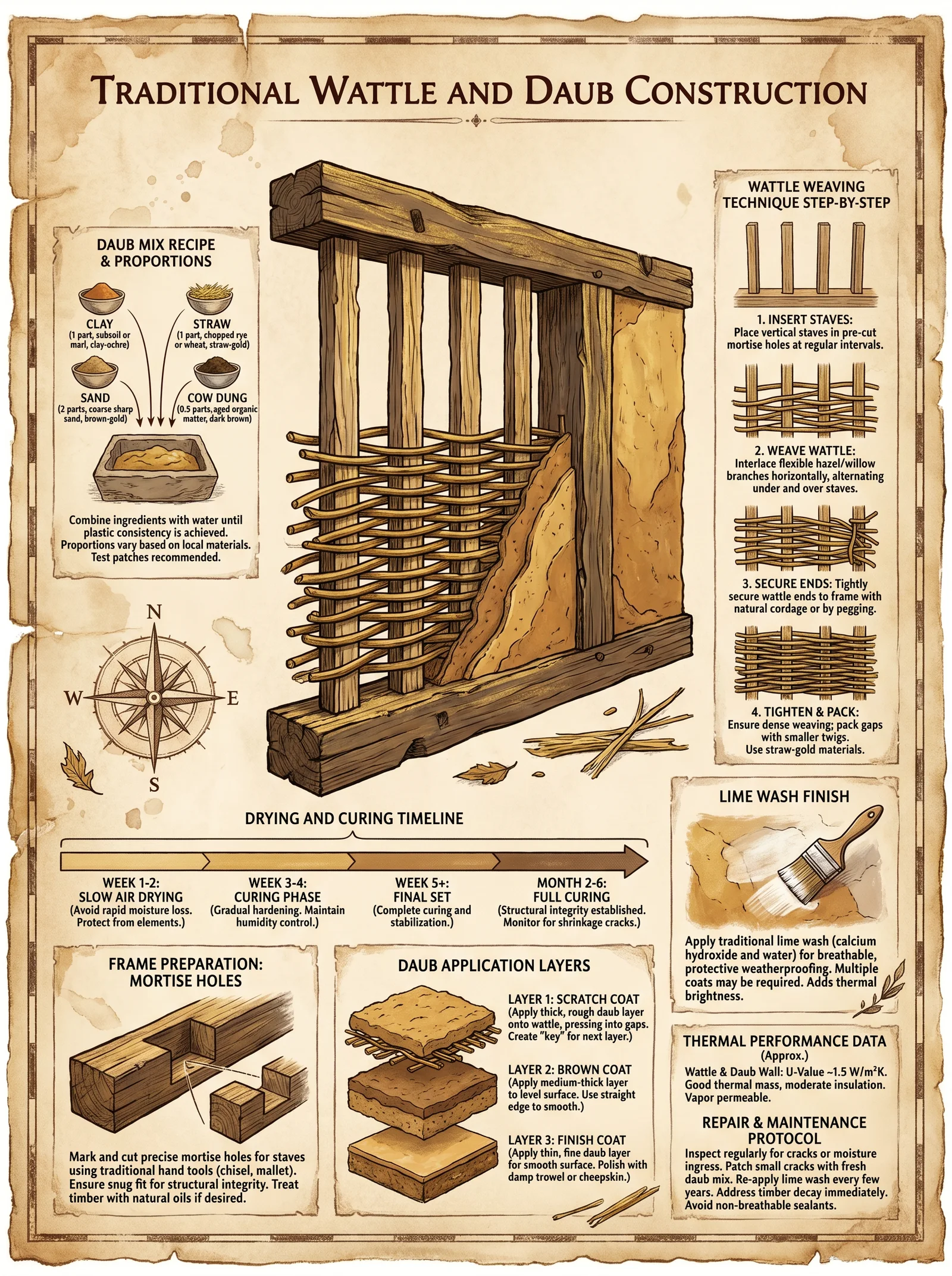
Wattle and daub construction consists of three principal components:
- The Wattle Frame: A rigid skeleton of vertical and horizontal wooden elements.
- The Wattle Weave: Interlaced flexible rods or slats forming a lattice.
- The Daub: A composite plaster mixture applied over the wattle to form a solid wall surface.
Each component demands precise material selection and execution protocols. Neglect or substitution leads to structural failure or material degradation.
Section 2: Fiber and Timber Selection for Wattle Frame and Weave
2.1 Timber for Frame
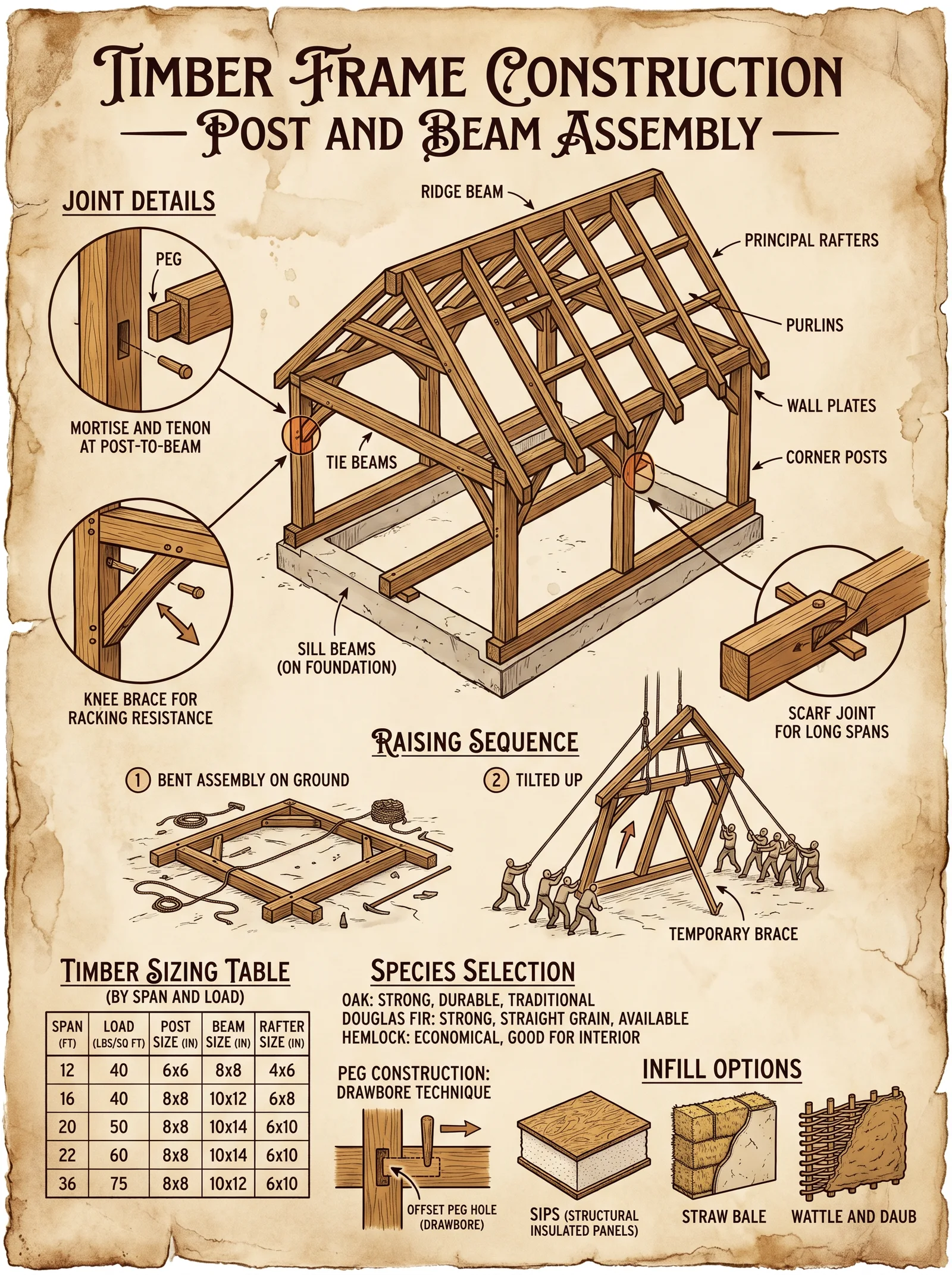
Requirements: High strength, straightness, minimal knots, natural resistance to decay.
Acceptable Species: Oak, Ash, Chestnut, Hazel, Willow.
| Property | Oak | Ash | Chestnut | Hazel | Willow |
|---|---|---|---|---|---|
| Density (kg/m³) | 700 | 690 | 560 | 600 | 500 |
| Modulus of Elasticity (GPa) | 11.5 | 12.0 | 9.5 | 8.0 | 7.0 |
| Decay Resistance | Very High | High | High | Medium | Low |
| Workability | Moderate | High | High | High | Very High |
Protocol 2.1.1: Frame Timber Preparation
- Select straight poles 4-6 cm diameter, length as per wall height plus 0.5 m for ground anchoring.
- Remove bark to deter insect infestation and fungal growth.
- Air-dry poles for minimum 3 weeks under cover, elevated from ground.
- Treat poles with natural preservative (see Volume 7: The Wood Codex, Chapter IV).
2.2 Flexible Rods for Wattle Weave
Preferred species: Hazel, Willow, Dogwood, Reed.
| Fiber Type | Flexibility (Bend Radius cm) | Diameter Range (cm) | Drying Time (days) | Durability (Years) |
|---|---|---|---|---|
| Hazel | 10 | 1.5-3.0 | 5 | 15 |
| Willow | 7 | 1.0-2.5 | 3 | 10 |
| Dogwood | 15 | 1.0-2.0 | 7 | 20 |
| Reed | 5 | 0.5-1.0 | 2 | 5 |
Section 3: Wattle Frame Erection Protocol
3.1 Foundation and Upright Posts
Objective: Establish vertical posts anchored securely to bear load.
| Step | Action | Details and Measurements |
|---|---|---|
| 1 | Mark wall perimeter | Use string and stakes, define length and height |
| 2 | Dig post holes | Diameter 30 cm, depth 60 cm minimum |
| 3 | Insert uprights | Place poles vertically, 50 cm spacing |
| 4 | Backfill and tamp soil | Compact soil to eliminate movement |
Step-by-step protocol:
- Clear and level the construction area.
- Mark positions of uprights at 50 cm intervals.
- Dig holes 30 cm diameter, 60 cm deep using a digging bar or spade.
- Insert poles vertically, ensuring plumb alignment with level.
- Backfill holes with native soil mixed with 20% crushed stone for drainage.
- Tamp soil firmly around poles to prevent wobble.
- Allow poles to settle for 48 hours before attaching horizontal rails.
Section 4: Horizontal Rails Installation
- Cut rails to length between uprights.
- Attach rails at heights of 30 cm, 90 cm, and 150 cm from the ground.
- Use wooden pegs or natural fiber lashings (see Volume 7: The Wood Codex, Chapter V) to fasten rails.
- Tighten lashings to ensure no play between poles and rails.
Section 5: Wattle Weaving Protocol
Objective: Interlace flexible rods horizontally through the frame rails creating a stable lattice.
| Step | Action | Details |
|---|---|---|
| 1 | Soak rods | 12 hours in water to increase pliability |
| 2 | Begin weaving at base | Insert rods alternately in front and behind uprights |
| 3 | Maintain tension | Keep rods taut to avoid sagging |
| 4 | Overlap ends | Overlap rods minimum 30 cm at joints |
| 5 | Trim excess ends | After weave completion |
Detailed weaving steps:
- Soak rods in water for 12 hours.
- Start weaving at the bottom rail.
- Pass rod behind the first upright, in front of the next, alternating along the row.
- Push rod tightly against the previous rod.
- Repeat for each subsequent row, staggering rods to overlap joints.
- Secure rod ends by tucking or tying with natural fiber.
- Inspect lattice for gaps or loose rods.
Section 6: Daub Preparation
6.1 Material Components
Daub is a mixture of clay, sand, fiber, and water. Additional animal manure and lime may be added for enhanced properties.
| Component | Function | Recommended Ratio (by volume) |
|---|---|---|
| Clay | Binder | 30% |
| Sand | Aggregate, reduces shrinkage | 40% |
| Straw or Fibers | Tensile reinforcement | 20% |
| Animal Manure | Enhances plasticity and curing | 5% |
| Lime (optional) | Antiseptic, increases durability | 5% |
6.2 Clay Slip (Liquid Clay) Preparation
Clay slip is a slurry used to wet the wattle before daub application, improving adhesion.
Slip recipe:
- Mix 2 parts clay to 3 parts water by volume.
- Stir vigorously until homogeneous with no lumps.
- Allow to settle for 12 hours.
- Decant excess water, retain thick slip layer.
Section 7: Daub Mixing Protocol
- Sift clay and sand to remove stones and impurities.
- Mix dry components (clay, sand, fibers) thoroughly.
- Add animal manure and lime if available.
- Add water incrementally, mixing continuously.
- A perfect mix achieves a stiff but workable consistency, akin to thick mud.
Section 8: Daub Application Methods
8.1 Pre-application Preparation
- Spray or brush the clay slip onto the wattle lattice, saturating fibers.
- Allow slip to penetrate and become tacky (approximately 30 minutes).
- Prepare daub in batches no larger than 10 liters for manageable application.
8.2 Application Steps
| Step | Action | Notes |
|---|---|---|
| 1 | Apply first daub layer | Thickness 1.5 cm |
| 2 | Press firmly to fill lattice gaps | Use trowel or hands (wear gloves) |
| 3 | Allow to dry partially | 24-48 hours, protect from sun and wind |
| 4 | Apply second daub layer | Thickness 1.5 cm |
| 5 | Scratch surface to improve adhesion | Use a stiff brush |
| 6 | Apply final finishing layer | Thickness 0.5 cm, smooth surface |
Section 9: Drying and Curing Protocol
Proper curing is vital to prevent cracking and ensure durability.
| Parameter | Recommended Value |
|---|---|
| Initial drying time | 48 hours (partial drying) |
| Full cure time | Minimum 21 days |
| Ambient conditions | 15-25°C, 50-70% humidity |
| Protection | Shade from direct sun, windbreaks |
Steps for curing:
- After final layer, cover walls with breathable fabric to moderate drying rate.
- Mist surface lightly every 12 hours to maintain moisture.
- Avoid heavy rainfall or freezing conditions during curing.
- Inspect for cracks; fill immediately with fresh daub mixture.
- After 21 days, remove coverings; walls should be hard and durable.
Section 10: Material Ratios for Daub Mixtures
| Recipe Variant | Clay (%) | Sand (%) | Fiber (%) | Manure (%) | Lime (%) | Notes |
|---|---|---|---|---|---|---|
| Basic | 30 | 40 | 20 | 5 | 5 | Balanced for most applications |
| High Fiber | 25 | 35 | 30 | 5 | 5 | Increased tensile strength, less shrinkage |
| Lime Enhanced | 25 | 40 | 20 | 5 | 10 | For improved durability and antiseptic effect |
| Rapid Drying | 35 | 45 | 15 | 3 | 2 | Lower fiber content, faster curing |
Section 11: Structural Properties of Wattle and Daub Walls
| Property | Value Range | Units | Notes |
|---|---|---|---|
| Compressive Strength | 1.5 - 3.0 | MPa | Comparable to low-grade adobe |
| Tensile Strength | 0.2 - 0.4 | MPa | Provided primarily by fiber matrix |
| Thermal Conductivity | 0.3 - 0.5 | W/m·K | Insulating properties vary with thickness |
| Wall Thickness | 10 - 15 | cm | Typical for structural and weather protection |
| Expected Lifespan | 15 - 30 | Years | With proper maintenance |
Section 12: Maintenance and Repair Procedures
- Inspect walls annually for cracks or erosion.
- Prepare fresh daub mixture matching original composition.
- Moisten damaged area lightly.
- Apply patch daub in layers, allowing partial drying between coats.
- Protect repaired areas during curing as per original protocol.
Closing Remarks
Mastery of wattle and daub is mastery of balance: between rigidity and flexibility, moisture and dryness, tradition and technique. Execute each step with unwavering precision and respect for materials' sacred properties. This knowledge, preserved through ages, shall fortify your constructions against time and turmoil.
For complementary construction methods and material treatments, refer to:
- Volume 7: The Wood Codex, Chapters IV and V for timber treatment and lashing techniques.
- Volume 8: The Earth Codex, Chapter III for soil and clay analysis.
- Volume 9: The Shelter Codex, Chapter I for structural design principles.
May your walls stand firm as the bulwarks of sanctuary.
<!-- SECTION 17 -->
The Complete Practitioner's Codex, Volume III: The Builder’s Testament
Earthship Design Principles: Sustainable Earthship Architecture, Systems Integration, and Construction Protocols

Preface
This volume delivers the sacred, suppressed knowledge of Earthship architecture, a holistic, sustainable building methodology blending ancient wisdom and precise engineering. Herein lies the uncompromising manual for constructing habitable fortresses in harmony with earth’s cycles, ensuring survivors thrive with minimal external resource dependence. The protocols demand exact adherence; deviation imperils structural integrity, habitability, and ecological balance.
Chapter I: Overview of Earthship Architecture Principles
Earthship design is a paradigm of passive sustainability using:
- Thermal Mass: Utilizing dense materials to absorb, store, and radiate heat, stabilizing internal temperatures.
- Passive Solar Strategies: Orientation and window placement to maximize winter solar gain and summer shading.
- Water Harvesting: Onsite capture, filtration, and storage of rainwater and greywater for potable and irrigation use.
- Waste Recycling Integration: Closed-loop systems converting human and organic waste into resources without contamination.
This chapter delivers exacting steps and data for layout, earth berming, tire wall construction, and system integration.
Chapter II: Earthship Layout Protocol
Earthship layout dictates thermal performance, water collection efficiency, and waste processing efficacy.
1. Site Selection and Orientation
| Parameter | Specification | Rationale |
|---|---|---|
| Latitude | 25° to 50° N or S | Optimal solar angles for passive heating |
| Slope | < 5° | Facilitates earth berming and drainage |
| Solar Azimuth | True South (Northern Hemisphere), True North (Southern Hemisphere) | Maximizes solar gain |
| Prevailing Winds | Identify dominant wind direction | Position earth berming as windbreak |
Step-by-Step:
- Survey site latitude and longitude. Use GPS or topographic maps.
- Determine true south (or north) using compass declination correction. Verify with solar noon observations.
- Assess slope gradient with clinometer. Ensure < 5 degrees; if steeper, terrace site.
- Identify prevailing wind direction via local meteorological data or wind sock observations.
- Select building footprint elongated along east-west axis.
2. Floor Plan Zoning
Earthship internal zoning must separate:
- Thermally controlled living spaces (south-facing).
- Service and waste processing zones (north or leeward side).
- Water storage cisterns adjacent to catchment surfaces.
Step-by-Step:
- Design living spaces with maximum south-facing glazing, approximately 60–70% of wall area.
- Allocate tire walls on north, east, and west for thermal mass and insulation.
- Position water cisterns downhill from roof catchment for gravity feed.
- Integrate waste processing chamber with access from service zones.
Chapter III: Earth Berming Protocol
Earth berming stabilizes internal temperature, shields from wind, and adds structural mass.
Material Specifications
| Material | Density (kg/m³) | Thermal Conductivity (W/m·K) | Compaction Requirement |
|---|---|---|---|
| Loam Soil | 1600 | 0.25 | 95% Proctor Density |
| Clay | 1800 | 0.55 | 90% Proctor Density |
| Gravel (subgrade) | 2000 | 1.3 | 98% Compacted |
Berm Construction Steps
- Excavate foundation trenches 0.6 m wide and 1.2 m deep along building perimeter.
- Compact gravel base at 98% compaction to 15 cm depth.
- Layer loam soil in 30 cm lifts, compacting each to 95% Proctor Density using vibratory plate compactor.
- Slope berm at 3:1 (horizontal:vertical) for stability.
- Seal berm surface with clay slurry (20% clay by volume mixed with water) to prevent erosion.
- Allow berm to settle for 7 days before proceeding with wall construction.
Chapter IV: Tire Wall Construction Protocol
Tire walls are the core thermal mass and structural element in Earthship design.
Material Specifications
| Component | Specification |
|---|---|
| Used tires | Radial passenger vehicle tires, 16–18 inches diameter |
| Fill material | Rammed earth (loam soil, moisture content 12–15%) |
| Binding agent | None (compaction achieves structural integrity) |
| Reinforcement | Rebar stakes (12 mm diameter, length 1.5 m) spaced every 1 m |
Step-by-Step Construction
- Prepare the foundation trench as per berming protocol beneath wall footprint.
- Place the first tire on foundation; ensure level using laser level.
- Fill tire with moistened loam soil; compact with pneumatic tamper or manual rod until firm and dense, no voids remain.
- Drive rebar stakes vertically through tire center, anchoring into foundation.
- Stack subsequent tires in offset pattern (running bond), interlocking for lateral stability.
- Repeat filling, compaction, and rebar insertion for each tire layer.
- Construct walls to minimum height of 2.4 m for living areas; 1.8 m for service zones.
- Apply wire mesh on exterior and interior surfaces for stucco application.
- Finish with cement-lime stucco (see Volume IV: The Mason’s Codex, Chapter V).
Chapter V: Thermal Mass and Passive Solar Strategy Integration
Thermal mass walls absorb solar heat during the day, releasing it at night, minimizing heating energy.
Thermal Performance Data
| Wall Type | Thickness (m) | Specific Heat (J/kg·K) | Density (kg/m³) | Thermal Capacity (MJ/m²·K) |
|---|---|---|---|---|
| Rammed Earth Tire Wall | 0.25 | 840 | 1600 | 336 |
| Earth Berm | 1.0 | 840 | 1600 | 1344 |
| Insulated Wood Frame | 0.15 | 1300 | 600 | 117 |
Step-by-Step Passive Solar Design
- Calculate solar altitude angle at winter solstice for site latitude.
- Design roof overhangs to shade windows during summer high sun angles but allow full winter sun penetration.
- Position windows with U-value < 1.5 W/m²·K facing true south (or true north in Southern Hemisphere).
- Install interior thermal shutters or heavy curtains for thermal retention at night.
- Incorporate skylights or solar tubes for daylighting in interior zones.
Chapter VI: Water Harvesting Systems Protocol
Earthships employ multiple water catchment and recycling systems for potable and non-potable use.
Rainwater Catchment Calculation
| Parameter | Formula | Example Values | Result |
|---|---|---|---|
| Catchment Area (m²) | Given | 100 m² | 100 m² |
| Rainfall (mm/year) | Local Meteorological Data | 600 mm/year | 600 mm/year |
| Runoff Coefficient | Surface Dependent | 0.9 (metal roof) | 0.9 |
| Annual Volume (m³/year) | Area x Rainfall x Coefficient / 1000 | 100 x 600 x 0.9 / 1000 | 54 m³/year |
Step-by-Step Water Catchment Construction
- Construct sloped metal or tile roof with minimum slope 15°.
- Install gutter system with leaf screens and first-flush diverters.
- Connect gutters to sealed cisterns fabricated from polyethylene or concrete, capacity minimum 10,000 liters.
- Seal cisterns with potable-grade sealant (see Volume VIII: The Water Codex, Chapter II).
- Install gravity-fed sediment filters and UV sterilization units for potable water supply.
Chapter VII: Waste Recycling Integration Protocol
Earthship waste systems separate and recycle greywater and blackwater, minimizing contamination.
Greywater Treatment
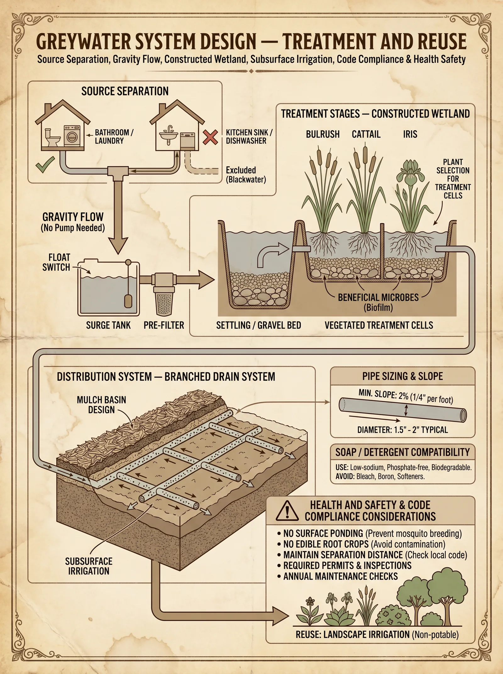
- Collect greywater from sinks, showers, and laundry.
- Direct greywater into botanical cells planted with wetland plants for phytoremediation.
- Use subsurface flow constructed wetlands with gravel media for filtration.
- Recycle treated greywater for irrigation of non-food plants.
Blackwater Treatment
- Install composting toilets with urine diversion to separate solid and liquid waste.
- Collect solid waste in sealed bins with sawdust or biochar to promote aerobic composting.
- Maintain compost temperature at 55°C for minimum 7 days to sanitize pathogens.
- Use finished compost as soil amendment for non-edible landscaping.
Appendices
Appendix A: Material Specifications Summary
| Material | Density (kg/m³) | Thermal Conductivity (W/m·K) | Moisture Content (%) | Compaction Requirement |
|---|---|---|---|---|
| Loam Soil | 1600 | 0.25 | 12–15 | 95% Proctor Density |
| Clay | 1800 | 0.55 | 15–20 | 90% Proctor Density |
| Gravel | 2000 | 1.3 | < 5 | 98% Compacted |
| Used Tires | N/A | N/A | N/A | Filled with rammed earth |
Appendix B: Thermal Performance Comparison
| Material | Thermal Mass (MJ/m²·K) | Insulation R-Value (m²·K/W) |
|---|---|---|
| Rammed Earth Tire Wall | 336 | 0.5 |
| Earth Berm | 1344 | 1.0 |
| Conventional Wood Frame | 117 | 3.5 |
Final Notes
The mastery of Earthship architecture lies in the precise integration of natural materials, passive solar dynamics, and closed-loop resource systems. The protocols delineated in this volume are sacred knowledge, tested by time and necessity. The apprentice must execute every instruction to the letter: the survival of your community depends upon it.
For detailed construction techniques related to stucco application and water purification, consult Volume IV: The Mason’s Codex, and Volume VIII: The Water Codex respectively.
End of Volume III: Earthship Design Principles
<!-- SECTION 18 -->
The Complete Practitioner's Codex, Volume III: Living Roof Construction
Chapter VII: Design and Installation of Green Roofs—Waterproofing, Drainage, Soil Substrate, and Plant Selection
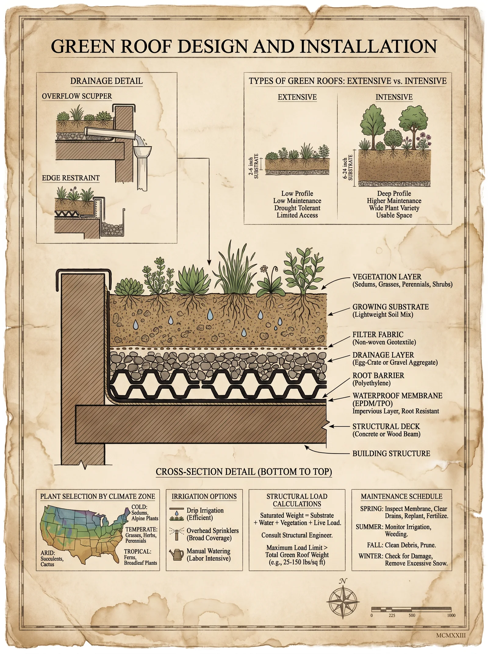
Preamble
The living roof is a sacred armor for the edifice, a covenant between human craft and nature’s resilience. This chapter delivers encrypted, field-proven protocols to construct living roofs capable of enduring relentless assaults of weather, gravity, and time. Each procedure is an invocation: precise, unyielding, and complete. Follow every step without deviation. The survival of both structure and occupant depends on your mastery.
Section 1: Roof Deck Preparation
The roof deck is the foundation of all subsequent layers. Imperfections here doom the entire system. Begin with an unyielding surface, clean, sound, and engineered to bear the load of the living roof assembly.
Protocol 1.1: Roof Deck Inspection and Reinforcement
- Inspect structural capacity: For existing structures, verify load capacity per Table 1.1. If capacity is insufficient, reinforce per Volume VI: Structural Fortification, Chapter IV before continuing.
- Surface cleaning: Remove all debris, loose particles, oils, and coatings incompatible with membrane adhesion using mechanical brushing and solvent wash (use isopropyl alcohol, 99% purity).
- Surface leveling: Fill cracks, voids, and uneven areas with polymer-modified cementitious compound. Allow curing for 24 hours minimum at 20°C.
- Priming: Apply a primer compatible with the waterproofing membrane (consult membrane manufacturer’s datasheet). Use roller or spray to achieve uniform coverage. Allow drying per manufacturer’s instructions.
Table 1.1: Load Capacities for Roof Decks (Dead + Live Loads in kg/m²)
| Roof Type | Max Load Capacity (kg/m²) | Notes |
|---|---|---|
| Reinforced Concrete | 500 | Suitable for extensive green roofs |
| Steel Deck | 350 | Requires corrosion protection |
| Wood Deck | 200 | Limited to lightweight, intensive systems |
| Precast Panels | 400 | Ensure joint sealing before proceeding |
Section 2: Waterproofing Membrane Installation
Waterproofing is the sacred veil that must never fail. It is the bulwark against water intrusion, rot, and structural degradation.
Protocol 2.1: Selection and Installation of Waterproofing Membrane
Membrane Types: Choose between bituminous, PVC, TPO, or EPDM membranes. EPDM is recommended for its elasticity and durability in green roof applications.
Steps:
- Membrane Layout: Roll out membrane sheets perpendicular to the slope to facilitate drainage. Overlap edges by minimum 100 mm.
- Seam Sealing: For EPDM, use adhesive and primer system supplied by manufacturer. Apply primer to both overlapping surfaces, allow tack time (approx. 10 minutes), apply adhesive evenly, and press firmly together.
- Detailing: Seal all penetrations (vents, pipes) using prefabricated boots or custom-fabricated patches. Use termination bars and sealants to secure edges.
- Inspection: Conduct a flood test by ponding 25 mm of water for 24 hours. Inspect for leaks; repair immediately.
Section 3: Drainage Layer Placement
Drainage must channel excess water away without impeding substrate moisture retention or root growth.
Protocol 3.1: Drainage Layer Construction
Materials:
- Drainage boards (HDPE or composite)
- Filter fabric (non-woven, minimum 150 g/m²)
Steps:
- Filter Fabric Installation: Lay filter fabric directly over waterproof membrane, ensuring full coverage with minimum 200 mm overlap at seams.
- Drainage Board Placement: Place drainage boards on top of filter fabric. Boards must fit tightly without gaps. Cut to size with utility knife.
- Edge Sealing: Seal edges of drainage boards with compatible adhesive to prevent displacement.
- Drainage Outlets: Connect drainage outlets or scuppers to drainage layer to evacuate water. Ensure outlets have debris protection.
Section 4: Soil Substrate Layer Construction
The soil substrate is the life-giving matrix. It must balance weight, water retention, drainage, and nutrient provision.
Protocol 4.1: Substrate Composition and Layering
Table 4.1: Recommended Substrate Compositions by Green Roof Type
| Component | Extensive (%) | Semi-Intensive (%) | Intensive (%) | Notes |
|---|---|---|---|---|
| Mineral Soil | 40 | 50 | 60 | Provides structure and nutrients |
| Organic Matter | 20 | 25 | 30 | Improves water retention |
| Sand | 35 | 20 | 5 | Enhances drainage |
| Perlite / Expanded Clay | 5 | 5 | 5 | Reduces weight |
Steps:
- Substrate Mixing: Combine components uniformly using a mechanical mixer or manual tilling. Ensure no clumps or large debris remain.
- Layer Application: Spread substrate evenly over drainage layer. Target thickness by green roof type per Table 4.2.
- Compaction: Lightly compact substrate by manual tamping to minimize settlement while preserving porosity.
- Moisture Conditioning: Moisten substrate to 50–60% field capacity for optimal planting conditions.
Table 4.2: Substrate Thickness and Load by Green Roof Type
| Green Roof Type | Substrate Thickness (mm) | Expected Load (kg/m²) | Suitable For |
|---|---|---|---|
| Extensive | 80–150 | 80–150 | Sedum, herbs, mosses |
| Semi-Intensive | 150–300 | 150–350 | Shrubs, grasses |
| Intensive | 300–600 | 350–600 | Small trees, shrubs |
Section 5: Plant Selection and Planting
Plants are the living shield. Their selection is strategic: drought tolerance, root behavior, growth habit, and maintenance demand must be balanced.
Protocol 5.1: Plant Selection Criteria
Table 5.1: Recommended Plant Species for Green Roofs
| Plant Type | Species Name | Growth Habit | Root Depth (mm) | Drought Tolerance | Maintenance Level | Application |
|---|---|---|---|---|---|---|
| Sedum | Sedum album | Mat-forming | 50 | High | Low | Extensive |
| Sedum | Sedum spurium | Mat-forming | 60 | High | Low | Extensive |
| Grass | Festuca ovina | Tufted | 150 | Medium | Medium | Semi-Intensive |
| Herbaceous | Allium schoenoprasum | Clumping | 200 | Medium | Medium | Semi-Intensive |
| Shrub | Cotoneaster dammeri | Spreading | 300 | Medium | Medium | Intensive |
| Small Tree | Betula nana | Upright | 500 | Medium | High | Intensive |
Steps:
- Plant Procurement: Obtain healthy, disease-free plants from certified nurseries. Ensure species match local climate conditions.
- Planting Preparation: Mark planting areas with a grid for uniform spacing based on species growth habit and mature size.
- Planting Execution: Dig holes in substrate 1.5 times root ball size. Place plants carefully to avoid root damage. Backfill and press substrate firmly.
- Watering: Immediately water plants to field capacity using drip irrigation or manual watering.
- Mulching: Apply 10 mm layer of organic mulch (bark chips or straw) to conserve moisture and suppress weeds.
Section 6: Maintenance and Monitoring Protocols
A living roof demands vigilant stewardship to sustain its sacred purpose.
Protocol 6.1: Initial 12-Month Maintenance Schedule
| Month | Task | Frequency | Details |
|---|---|---|---|
| 1-3 | Watering | Twice weekly | Maintain soil moisture; avoid waterlogging |
| 1-6 | Weed Removal | Monthly | Manual removal only; chemical herbicides forbidden |
| 3-12 | Fertilization | Quarterly | Use slow-release NPK fertilizer; 10-10-10 ratio |
| 6-12 | Plant Health Inspection | Bi-monthly | Check for pests, diseases, root damage |
| 12 | Substrate Replenishment (if needed) | Annually | Add 20 mm of substrate to compensate for loss |
Summary Table: Complete Living Roof Layer Assembly
| Layer | Thickness (mm) | Material | Purpose |
|---|---|---|---|
| Vegetation | Variable | Selected plants | Living cover, thermal insulation |
| Mulch | 10 | Organic mulch | Moisture retention, weed suppression |
| Soil Substrate | 80–600 | Engineered blend (mineral + organic) | Plant growth medium |
| Drainage Layer | 20–50 | HDPE drainage boards + filter fabric | Water evacuation |
| Waterproof Membrane | 1.2–2.0 | EPDM or equivalent membrane | Impermeability |
| Roof Deck | Variable | Concrete, steel, or wood | Structural support |
Appendix: Equipment and Tools Required
| Equipment/Tool | Purpose | Specifications/Notes |
|---|---|---|
| Mechanical mixer | Substrate mixing | Capacity ≥ 100 liters |
| Utility knife | Cutting membrane and drainage boards | Sharp, replace blades frequently |
| Roller or sprayer | Primer and adhesive application | Ensure even coating |
| Tamping tool | Substrate compaction | Lightweight, non-damaging to membrane |
| Watering system | Plant irrigation | Drip irrigation recommended |
| Flood testing equipment | Waterproofing inspection | Water retention barriers or plugs |
Final Edict
The living roof is a fortress forged in the union of elemental mastery and biological resilience. Every layer, every plant, every molecule of substrate is a soldier in this eternal battle against entropy. Your hands must be steady, your mind sharp, and your heart unwavering. This testament is your sacred script—inscribe it into your craft, and the roof shall endure beyond your mortal span.
For advanced water management and purification protocols integral to the living roof irrigation system, consult Volume VIII: The Water Codex, Chapter II.
End of Volume III, Chapter VII: Living Roof Construction.
<!-- SECTION 19 -->
The Complete Practitioner's Codex, Volume IV
The Builder's Testament: Post and Beam Timber Framing
Chapter I: Traditional Post and Beam Construction
Introduction
The art of Post and Beam Timber Framing stands as the cornerstone of sacred architecture, a discipline melding structural integrity, material wisdom, and timeless craftsmanship. This volume delivers an uncompromising guide to the selection, preparation, joinery, assembly, and raising of post and beam frameworks, essential for any master builder seeking to construct enduring sanctuaries or fortifications. Every protocol herein is precise, unvarnished, and exhaustive, designed to preserve life and legacy.
Section 1: Timber Selection
The foundation of any post and beam structure is the timber itself. Selection criteria are dictated by species properties, dimensional stability, strength, and resistance to environmental degradation.
1.1 Timber Species Properties
The following table catalogs essential properties of recommended species:
| Species | Density (kg/m³) | Modulus of Elasticity (GPa) | Bending Strength (MPa) | Decay Resistance | Workability | Common Use in Framing |
|---|---|---|---|---|---|---|
| White Oak | 740 | 12.4 | 90 | High | Moderate | Posts, Beams |
| Douglas Fir | 530 | 13.8 | 85 | Moderate | High | Beams, Joists |
| Southern Yellow Pine | 650 | 12.0 | 100 | Moderate | Moderate | Heavy Beams, Posts |
| Eastern Hemlock | 510 | 9.0 | 65 | Low | High | Secondary framing |
| Western Red Cedar | 370 | 8.5 | 55 | Very High | Very High | Posts, Exposed Elements |
| Chestnut (Castanea) | 560 | 10.5 | 70 | High | Moderate | Posts, Beams (historical) |
Selection Protocol:
- Determine structural load requirements (see Section 3).
- Identify environmental exposure (indoor, outdoor, ground contact).
- Cross-reference species with decay resistance and strength.
- Prioritize White Oak or Douglas Fir for primary load-bearing elements.
- Utilize Western Red Cedar for exposed elements requiring decay resistance.
- Reject timber with visible defects: cracks, rot, insect damage.
Section 2: Timber Preparation
Timber preparation transforms raw logs into dimensionally stable, workable members ready for joinery.
2.1 Felling and Initial Milling
- Select mature trees, minimum diameter 30 cm at breast height.
- Fell using crosscut saw or chainsaw ensuring minimal shock to fibers.
- Limb and buck logs into lengths 4.0 m to 6.0 m, depending on design.
- Mill to rough dimensions 25 mm larger than final dimensions to allow for dressing.
2.2 Drying Protocol
Air Drying:
- Stack timber with 25 mm stickers every 600 mm to allow airflow.
- Cover top to prevent rainfall but leave sides open.
- Allow minimum 12 months drying for beams thicker than 150 mm.
- Verify moisture content with a pin or resistance-type moisture meter; target 15% or below.
Kiln Drying (if available):
- Set kiln temperature to 60°C maximum to avoid checking.
- Maintain relative humidity at 50-60%.
- Dry until moisture content reaches 12-15%.
- Gradually cool and remove timber immediately to prevent mold.
2.3 Dressing and Dimensioning
- Plane or hand adze all faces to final dimensions.
- Square edges with a framing square and marking gauge.
- Mark grain direction; ensure beams are oriented with growth rings convex toward the tension face to minimize warping.
Section 3: Beam Sizing and Structural Calculations
Correct beam sizing is non-negotiable for structural safety.
3.1 Load Considerations
- Dead Load: Weight of beams, roofing, cladding.
- Live Load: Occupants, furniture, snow.
- Environmental Load: Wind, seismic forces (refer to Volume X for detailed seismic codes).
3.2 Beam Sizing Chart (Span vs. Size for Douglas Fir, Sawn Lumber)
| Span (m) | Minimum Beam Dimensions (mm) | Notes |
|---|---|---|
| 2.0 | 100 x 150 | Single load-bearing beam |
| 3.0 | 125 x 200 | Light roof or floor load |
| 4.0 | 150 x 250 | Moderate load, open span |
| 5.0 | 200 x 300 | Heavy roof load |
| 6.0 | 225 x 350 | Requires bracing, engineered joinery |
Sizing Protocol:
- Calculate total load per beam length.
- Select species and cross-check with the above chart or perform exact calculations (see Volume II: Structural Mechanics).
- Oversize beams by 10% for safety and material defects.
Section 4: Joinery Design
Post and beam joinery is the sacred bond holding the structure’s integrity. Precision and fit are paramount.
4.1 Common Joint Types
| Joint Name | Description | Load Type | Complexity | Application |
|---|---|---|---|---|
| Mortise and Tenon | Rectangular peg-in-hole | Tensile and Shear | High | Primary beam to post |
| Dovetail | Tapered interlocking joint | Tensile and Compression | Very High | Beam to post, resisting withdrawal |
| Half-lap | Overlapping joint removing half thickness | Shear and Compression | Moderate | Secondary framing |
| Scarf | Long angled joint to splice beams | Bending and Shear | High | Extending beam length |
| Brace Mortise | Angled mortise for bracing elements | Compression and Tension | Moderate | Structural bracing |
Section 5: Joinery Protocols
5.1 Mortise and Tenon Joint Cutting
Tools Required: Mortise chisel set, mallet, marking gauge, bevel square, handsaw.
Steps:
- Mark tenon on beam end: length = 1/3 beam thickness; width = 2/3 beam width.
- Mark corresponding mortise on post, centered and aligned.
- Cut tenon cheeks with handsaw on marked lines.
- Clean tenon cheeks with chisel for exact fit.
- Use mortise chisel to remove waste from mortise area, depth matching tenon length.
- Test fit; adjust with chisel for snug, no-wobble fit.
- Drill peg holes 15 mm diameter, 50 mm from joint face, perpendicular to joint plane.
- Insert hardwood pegs (oak recommended), taper pegs slightly for tight fit.
5.2 Dovetail Joint Cutting
Steps:
- Mark dovetail shape on beam end; tails taper from 20° to 30°.
- Saw along marked lines, remove waste with chisel.
- Mark matching pin shape on post, transfer carefully.
- Saw and chisel pins to exact fit.
- Test assemble; ensure no play.
- Peg with hardwood dowels if required for added security.
Section 6: Structural Bracing
Bracing preserves frame stability against lateral forces.
6.1 Brace Types
- Knee Braces: Diagonal braces connecting post to beam at approximately 45°.
- Corner Braces: Placed at frame corners for torsional rigidity.
- Raking Braces: Longitudinal braces resisting racking forces.
6.2 Brace Preparation
- Select brace timber with minimum 75 mm thickness.
- Cut brace length to fit snugly between post and beam.
- Cut mortises or half-lap joints on ends for secure connection.
- Fit brace with tight joints; peg or wedge as necessary.
6.3 Brace Installation Steps
- Position brace in place, ensuring correct angle.
- Mark and cut mortise or lap joints on frame members.
- Fit brace, verify tight fit.
- Secure with hardwood pegs or trenails.
- For critical frames, use iron straps or bolts (refer to Volume VII: Metal Reinforcements).
Section 7: Layout Procedures
Precision layout underpins successful framing.
7.1 Tools Needed
- Carpenter's square
- Marking gauge
- Chalk line
- Plumb bob
- Measuring tape
- Scribe tool
7.2 Step-by-Step Layout for a Post and Beam Frame
- Establish a baseline on the timber using chalk line.
- Mark post locations according to design spacing.
- Use carpenter's square to lay out mortise positions on posts.
- Mark tenon dimensions on beams using marking gauge.
- Scribe shoulder lines on tenons for precise cutting.
- Double-check all dimensions before cutting.
Section 8: Assembly Protocol
8.1 Dry Assembly (Test Fit)
- Lay out all beams and posts on level ground.
- Assemble all joints without pegs to verify fit.
- Adjust any joints showing looseness or misalignment.
- Confirm squareness and plumb of frame.
8.2 Final Assembly
- Disassemble after dry fit.
- Apply linseed oil or beeswax to joint surfaces to prevent shrinkage and ease assembly.
- Reassemble frame on the ground.
- Insert pegs into mortise and tenon joints, driving them flush.
- Install braces and secure with pegs.
- Use temporary bracing or scaffolding as necessary.
Section 9: Raising the Frame
Raising the frame demands coordinated effort and precise control.
9.1 Pre-Raising Checks
- Verify all pegs fully inserted.
- Check braces installed.
- Confirm site level and footing readiness.
9.2 Raising Steps
- Position base of posts on prepared footings.
- Use levers, ropes, and manpower to raise posts upright.
- Temporarily brace posts with stakes.
- Lift beams onto posts, engage joints carefully.
- Drive pegs home, tighten all joints.
- Install permanent diagonal bracing.
- Secure with additional pegging or bolting as required.
Appendix: Common Joint Dimensions
| Joint Type | Tenon Length (mm) | Tenon Width (mm) | Mortise Depth (mm) | Peg Diameter (mm) |
|---|---|---|---|---|
| Mortise and Tenon | 75-150 | 40-80 | 75-150 | 15-20 |
| Dovetail | 80-120 | 50-70 | N/A | 15 |
| Half-lap | 50-100 | 50-100 | N/A | N/A |
| Scarf | 150-300 | Beam thickness | N/A | 20 |
Final Words
Mastery of post and beam timber framing is not merely a skill but a sacred trust passed through generations. Every cut, joint, and assembly carries the weight of legacy and survival. This volume delivers the life-or-death precision necessary to wield timber as a vessel for sanctuary and strength.
For detailed protocols on timber treatment, preservation, and advanced structural analysis, consult Volume II: Structural Mechanics and Volume VIII: Timber Preservation Codex.
End of Volume IV: Post and Beam Timber Framing.
<!-- SECTION 20 -->
Volume IV: Japanese Wood Joinery
Chapter I: The Builder’s Testament on Japanese Joinery Techniques — Mastery of Complex Interlocking Joints Without Metal Fasteners
Introduction: The Sacred Art of Japanese Wood Joinery
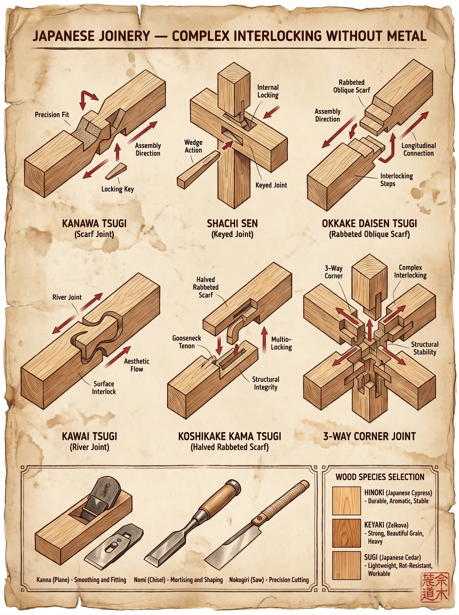
The Japanese tradition of wood joinery stands as a pinnacle of architectural and artisanal mastery, preserving sacred knowledge that transcends mere construction. Each joint is a living testament to centuries of refinement, designed to marry strength, flexibility, and aesthetic purity without reliance on metal fasteners. This chapter imparts a comprehensive, stepwise methodology for mastering the most vital joints, with a focus on the Kanawa Tsugi and Kumiki assemblies. Every detail is laid bare: layout, cutting, fitting, and assembly protocols, alongside essential tool specifications and joint performance data.
Section I: Fundamental Principles and Tool Preparation
Before engaging any joinery, the master builder must understand the fundamental principles governing Japanese wood joinery:
- Interlocking Geometry: Joints rely on precise geometry to transfer load and resist shear and tensile forces without nails or screws.
- Wood Grain Orientation: Grain alignment maximizes joint strength; typically, long grain-to-long grain contact is essential.
- Wood Selection: Seasoned, straight-grained hardwoods (e.g., sugi, keyaki) are preferred for their dimensional stability and resilience.
Tools Required for Precision Japanese Joinery
| Tool Name | Purpose | Specification | Notes |
|---|---|---|---|
| Ryoba Saw | Dual-toothed saw for cross and rip cuts | 240 mm blade, 1.0 mm kerf | Essential for precise cuts |
| Dozuki Saw | Fine-toothed backsaw for tenon, dado | 180 mm blade, 0.5 mm kerf | Critical for accurate joinery |
| Kanna Plane | Smoothing and fine shaping | Adjustable blade, 100 mm width | For perfect fit and surface prep |
| Nomi Chisels | Mortise and tenon cutting | Set of chisels 6,12,18,24 mm widths | Sharp, beveled for clean cuts |
| Sumitsubo (Ink Line) | Layout and marking | Silk thread, ink reservoir | Ensures straight and exact lines |
| Takebari (Measuring) | Marking lengths and angles | Steel ruler, square, bevel gauge | Durable and precise |
| Mawashibiki | Marking gauge for consistent depths | Brass or steel adjustable | For repeatable cuts |
Section II: Kanawa Tsugi Joint — The Sacred Scarf Joint
Purpose and Application
The Kanawa Tsugi (literally "crane scarf joint") is a complex, interlocking scarf joint used to connect two timber members end-to-end with superior tensile and shear strength. Its design accommodates both longitudinal stress and bending moments, making it indispensable in beam repairs and extensions.
Step-by-Step Protocol for Kanawa Tsugi Layout and Fabrication
Materials and Dimensions
| Timber Cross-Section | Standard Joint Length (L) | Tenon Width (W) | Tenon Thickness (T) | Mortise Depth (D) |
|---|---|---|---|---|
| 90 x 90 mm | 270 mm | 30 mm | 15 mm | 15 mm |
| 120 x 120 mm | 360 mm | 40 mm | 20 mm | 20 mm |
| 150 x 150 mm | 450 mm | 50 mm | 25 mm | 25 mm |
Note: Dimensions scale proportionally with timber size.
Layout Procedure
- Mark the Timber Length: Using the steel ruler, measure and mark the total joint length (L) from the timber ends.
- Determine Tenon and Mortise Placement: Mark the tenon width (W) and thickness (T) on the timber faces as per the table above.
- Draw Layout Lines: Use the sumitsubo ink line to mark crisp, straight lines for tenon shoulders and mortise boundaries.
- Mark Interlocking Hooks: Sketch the crane-hook profile on the tenon and mortise areas according to the Kanawa Tsugi geometry (see Figure 1).
Cutting Procedure
- Cut Tenon Shoulders: Using the dozuki saw, carefully cut along the shoulder lines to the marked depth.
- Saw Tenon Profile: Carefully saw the interlocking hook profiles on the tenon ends.
- Chisel Mortises: Using nomi chisels, remove wood from the mortise areas, chiseling precisely to the marked depth and profile.
- Test Fit: Insert tenon into mortise; check for tightness without forcing. Adjust with kanna plane or chisel for perfect fit.
Assembly Procedure
- Dry Fit Test: Assemble joint without adhesive to verify interlocking integrity.
- Apply Natural Adhesive: Optionally, apply rice glue (see Volume 8: The Water Codex, Chapter III for preparation) to joint surfaces.
- Final Assembly: Insert tenon into mortise, ensuring hooks fully interlock.
- Clamp and Cure: Use wooden clamps or rope bindings to maintain compression during glue curing (minimum 24 hours at 20°C).
Kanawa Tsugi Joint Stress Tolerances
| Load Type | Maximum Load (90x90 mm Timber) | Maximum Load (150x150 mm Timber) | Notes |
|---|---|---|---|
| Tensile Strength | 1,200 kgf | 2,800 kgf | Longitudinal pull |
| Shear Strength | 900 kgf | 2,100 kgf | Perpendicular to grain axis |
| Bending Moment | 150 N·m | 400 N·m | Applied at joint center |
Section III: Kumiki Assembly — The Interlocking Puzzle
Purpose and Application
Kumiki ("joining wood") is a family of interlocking joinery techniques used to construct three-dimensional wooden puzzles, furniture, and structural frameworks with no metal fasteners. The technique demands precision and an intimate understanding of complex joint geometries.
Case Study: Kumiki Mortise and Tenon Interlock Joint
Materials and Dimensions
| Timber Cross-Section | Mortise Width (MW) | Mortise Depth (MD) | Tenon Width (TW) | Tenon Length (TL) |
|---|---|---|---|---|
| 60 x 60 mm | 20 mm | 15 mm | 20 mm | 20 mm |
| 90 x 90 mm | 30 mm | 20 mm | 30 mm | 25 mm |
| 120 x 120 mm | 40 mm | 25 mm | 40 mm | 30 mm |
Step-by-Step Protocol for Kumiki Joint Fabrication
Layout and Marking
- Mark Timber Faces: Using takebari, mark mortise and tenon dimensions on respective timber members.
- Transfer Markings: Use sumitsubo to draw precise guide lines on all faces.
- Define Interlocking Surfaces: Mark hook and locking tab profiles on both mortise and tenon components.
Cutting Procedure
- Cut Tenon: With dozuki saw, cut tenon shoulders and cheeks according to layout.
- Chisel Mortise: Remove wood from mortise area with nomi chisels, creating clean, square edges.
- Shape Locking Tabs: Carefully carve the locking tabs that enable the self-locking action.
- Fine Adjustment: Use kanna plane to refine mating surfaces for friction fit.
Assembly Procedure
- Dry Assembly: Test fit pieces to verify locking function without gaps or excessive force.
- Apply Adhesive: Optionally apply natural glue to locking faces for permanent assembly.
- Final Join: Insert tenon into mortise, engage locking tabs securely.
- Clamp: Maintain pressure during curing phase as necessary.
Kumiki Joint Stress Performance
| Joint Dimension (mm) | Maximum Load (kgf) | Durability Rating (Cycles) | Notes |
|---|---|---|---|
| 60 Mortise x 20 | 450 | 10,000 | Suitable for small furniture |
| 90 Mortise x 30 | 900 | 25,000 | Medium structural elements |
| 120 Mortise x 40 | 1,500 | 40,000 | Heavy load-bearing framework |
Section IV: Comparative Table of Common Japanese Wood Joints
| Joint Name | Primary Use | Metal Fasteners | Strength Characteristics | Complexity Level | Key Tools |
|---|---|---|---|---|---|
| Kanawa Tsugi | Beam extension | No | High tensile and shear | High | Ryoba, Nomi, Dozuki |
| Kumiki | Furniture, puzzles | No | High friction and locking | Medium-High | Dozuki, Kanna, Nomi |
| Shiguchi | Corner joint | No | Moderate shear, flexible | Medium | Dozuki, Nomi |
| Dovetail (Ari) | Drawer joints, frames | No | High tensile, resistant | Medium | Dozuki, Nomi |
Section V: Maintenance and Longevity Protocols
- Annual Inspection: Check joints for looseness or wood movement. Record measurements with calipers.
- Re-tightening: If joints loosen, disassemble carefully and plane mating surfaces before reassembly.
- Moisture Control: Ensure timber moisture content remains between 8%-12% to prevent swelling or cracking.
- Surface Protection: Apply natural oils or lacquers to prevent UV and insect damage.
Final Words to the Apprentice
The mastery of Japanese wood joinery demands unwavering discipline, precision, and reverence for the living timber. Each joint embodies a sacred covenant between builder, material, and the forces of nature. Through diligent practice of the outlined protocols, you will transcend the mechanical and step into the realm of artistry and structural sanctity. Preserve this knowledge, for it is the backbone of all enduring construction.
For further exploration of timber selection, wood moisture management, and advanced carving tools, consult Volume II: The Sacred Timber Codex, Chapters IV and VII.
<!-- SECTION 21 -->
The Complete Practitioner's Codex, Volume IV: Log Cabin Construction
Chapter I: Introduction to Log Cabin Construction
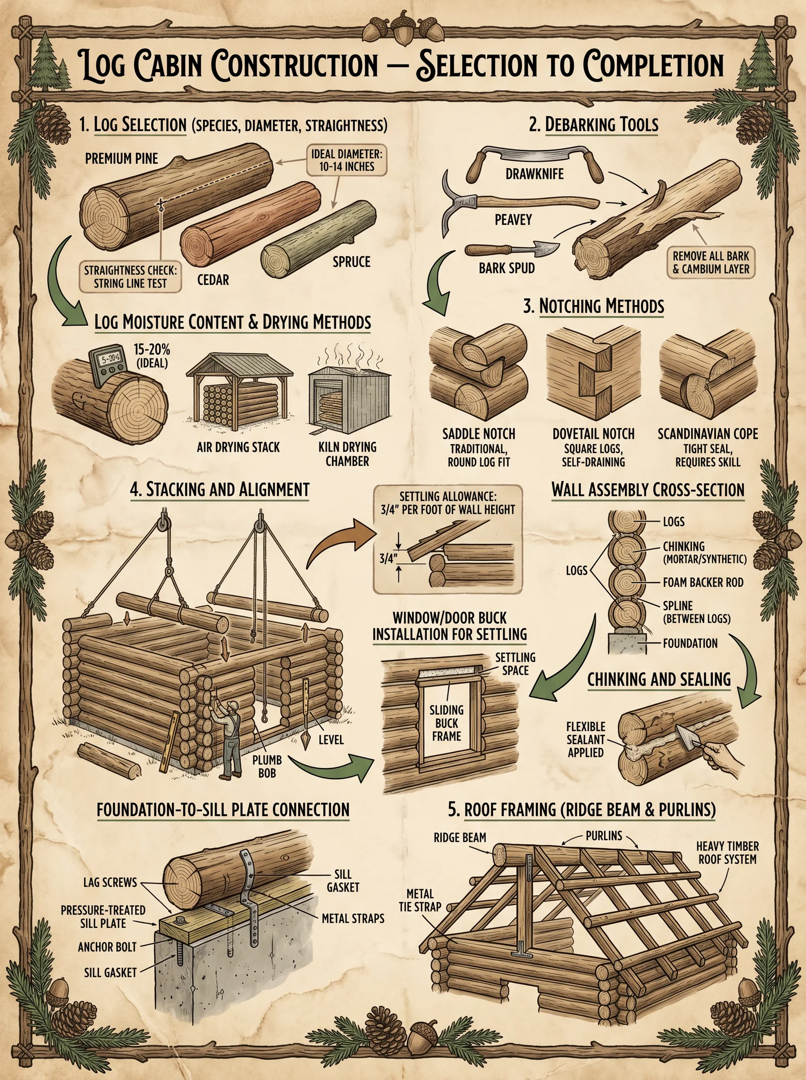
Log cabins stand as timeless sanctuaries, embodying resilience and harmony with the earth. This volume transmits the sacred, suppressed knowledge essential to constructing these fortresses of survival. The protocols herein mandate precision: from log selection through roof framing, every detail serves life preservation.
Chapter II: Log Selection and Preparation
2.1 Log Species Selection
The choice of wood species determines structural integrity, longevity, and environmental resilience. The following table catalogs optimal species, accompanied by their mechanical properties, typical moisture content at felling, and decay resistance.
| Species | Density (kg/m³) | Modulus of Rupture (MPa) | Typical Moisture Content at Felling (%) | Decay Resistance Rating¹ |
|---|---|---|---|---|
| Eastern White Pine | 400 | 50 | 50–60 | Moderate |
| Northern White Cedar | 350 | 40 | 45–55 | High |
| Douglas Fir | 530 | 85 | 50–65 | Moderate-High |
| Red Oak | 700 | 90 | 50–60 | Low |
| Black Spruce | 400 | 48 | 50–60 | Moderate |
¹Decay resistance rating follows the Wood Durability Scale: High (resists decay >20 years exposed), Moderate (10–20 years), Low (<10 years).
Actionable Protocol 2.1: Selecting Suitable Logs
- Survey the local forested area, identifying trees matching species in the table.
- Prioritize species with High decay resistance for exterior walls.
- Select trees with straight trunks and minimal taper.
- Avoid trees with excessive knots, cracks, or infestations.
- Measure diameter at breast height (DBH); optimal logs range between 20–35 cm (8–14 inches) diameter.
- Confirm moisture content via a handheld moisture meter; ideal felling moisture content is 50–60% for ease of peeling and shaping.
2.2 Log Felling
Felling must be executed with precision to preserve log integrity and safety.
Tools Required:
- Felling axe (sharp, balanced)
- Crosscut saw or chainsaw
- Felling wedges (wood or plastic)
- Protective gear (helmet, gloves, boots)
Step-by-Step Protocol 2.2: Felling
- Assess Tree Lean: Determine natural lean direction.
- Clear Felling Path: Remove obstacles on the lean side.
- Make the Face Cut:
- Position yourself perpendicular to lean.
- Using the axe or saw, cut a notch on the lean side, approx. 1/3 of trunk diameter deep.
- The notch angle should be 70 degrees, with a flat bottom.
- Make the Back Cut:
- On the opposite side, make a horizontal cut slightly above the notch bottom.
- Insert felling wedges to prevent premature tree fall and control direction.
- Retreat Safely: Step back along a pre-planned path at 45 degrees from lean side.
- Observe Tree Fall: Allow tree to fall naturally; never force with wedges beyond resistance.
2.3 Log Peeling
Peeling the bark prevents insect infestation and promotes drying.
Tools Required:
- Draw knife (blade ~20 cm)
- Bark spud or peeling spade
- Water source (optional)
Step-by-Step Protocol 2.3: Peeling
- Position log horizontally on supports, elevated 30 cm off ground.
- Begin at butt end; insert bark spud under edge of bark.
- Pry bark away slowly, working around circumference.
- Use draw knife to shave residual cambium; angle blade at 30 degrees.
- Remove all loose bark, especially near knots.
- If bark resists, wet bark lightly and wait 24 hours before reattempting.
Chapter III: Notching Methods
The interlocking of logs via notching dictates cabin strength and weatherproofing. Choose the notch type aligned with your skill and local conditions.
3.1 Common Notching Types
| Notch Type | Description | Structural Strength | Ease of Construction | Weather Tightness |
|---|---|---|---|---|
| Saddle Notch | Concave notch fits over log below | High | Moderate | High |
| V-Notch | V-shaped cuts on both logs | Moderate | Easy | Moderate |
| Square Notch | Simple rectangular notch | Low | Easy | Low |
| Dovetail Notch | Tapered trapezoidal notch with lock | Very High | Difficult | Very High |
3.2 Saddle Notch Construction Protocol
Tools Required:
- Draw knife
- Froe and mallet
- Chisel set
- Marking gauge or pencil
- Measuring tape
Step-by-Step Protocol 3.2:
- Place lower log securely on supports.
- Lay upper log atop lower log, align lengthwise.
- Mark the curve of the lower log’s surface onto the upper log using a marking gauge.
- Using draw knife and chisel, carve a concave notch matching the lower log’s diameter curvature.
- Test fit; adjust notch depth for snug, immobile fit.
- Repeat for every log in sequence, ensuring consistent notch dimensions.
3.3 Dovetail Notch Construction Protocol
Tools Required:
- Handsaw (fine-toothed)
- Chisels
- Mallet
- Measuring tools (square, ruler)
- Marking knife
Step-by-Step Protocol 3.3:
- Measure and mark a trapezoidal notch on the end of each log, with the wider base inside.
- Saw vertical cuts at notch edges, depth matching notch height.
- Remove waste wood with chisel, forming a tight trapezoidal slot.
- On mating log, cut a matching trapezoidal tenon.
- Test fit, adjusting for a friction lock fit.
- Repeat for all logs, verifying uniformity.
Chapter IV: Stacking and Alignment
Stacking logs is a sacred act that demands precision for stability and weatherproofing.
4.1 Horizontal Spacing and Overlap
The spacing and overlap of logs influence structural integrity. The following table outlines minimum spacing and overlap dimensions by log diameter.
| Log Diameter (cm) | Minimum Overlap per Corner (cm) | Minimum Horizontal Spacing (cm) |
|---|---|---|
| 20–25 | 30 | 1–2 |
| 26–30 | 35 | 2–3 |
| 31–35 | 40 | 3–4 |
Protocol 4.1: Stacking
- Lay the first course of logs on a prepared foundation, ensuring level and square placement.
- Notch corners with minimum overlap per table specification.
- Place subsequent logs atop previous course, fitting notches tightly.
- Align logs lengthwise with maximum deviation of 3 mm per meter.
- Use wooden pegs (dowels) or rebar to pin logs vertically at 1.5-meter intervals.
4.2 Vertical Pegging (Trunnels) Protocol
Materials Required:
- Hardwood dowels (25–30 mm diameter, 40 cm length)
- Drill with auger bit (25 mm)
- Mallet
Step-by-Step Protocol 4.2:
- Drill vertical holes through two stacked logs at marked intervals.
- Insert hardwood dowels, driving flush with mallet.
- Ensure dowels are dry wood to swell and tighten with seasonal moisture changes.
Chapter V: Chinking and Sealing
Chinking seals gaps between logs, preventing drafts, moisture ingress, and insect penetration.
5.1 Chinking Materials
Traditional chinking compounds consist of:
| Component | Purpose | Typical Ratio (by volume) |
|---|---|---|
| Clay | Base filler | 2 parts |
| Sand | Structural aggregate | 2 parts |
| Straw or Fibers | Tensile reinforcement | 1 part |
| Lime | Antimicrobial, binder | 0.5 part |
| Water | Mixing medium | As needed for consistency |
5.2 Chinking Application Protocol
Tools Required:
- Trowel
- Mixing container
- Water spray bottle
- Wire brush
Step-by-Step Protocol 5.2:
- Clean gaps between logs of debris and loose material using wire brush.
- Moisten gaps lightly with water spray to enhance adhesion.
- Mix chinking ingredients thoroughly until a pliable, dough-like consistency forms.
- Apply chinking by hand or trowel, pressing firmly into gaps.
- Smooth chinking flush with log surfaces.
- Allow to dry for 48 hours, misting periodically to prevent cracking.
- Apply additional coat if gaps exceed 10 mm width.
Chapter VI: Roof Framing
The roof protects the sanctuary’s sanctity, demanding robust framing and waterproofing.
6.1 Roof Framing Design Parameters
| Roof Type | Pitch Angle (Degrees) | Rafter Spacing (cm) | Suitable for Snow Load (kg/m²) |
|---|---|---|---|
| Gable Roof | 30–45 | 60 | Up to 150 |
| Saltbox Roof | 20–35 | 50 | Up to 120 |
| Shed Roof | 10–20 | 40 | Up to 80 |
6.2 Rafter Construction Protocol
Materials:
- Selected logs or sawn timber, length to span roof
- Metal or wooden connectors
- Nails or wooden pegs
Tools:
- Saw
- Hammer or mallet
- Measuring tape
- Carpenter’s square
Step-by-Step Protocol 6.2:
- Measure cabin width; calculate rafter length using pitch angle and span.
- Cut rafters to calculated length, bevel ends to fit ridge beam and wall plate.
- Install ridge beam centrally along cabin length, supported by vertical posts as needed.
- Fix wall plates atop wall logs, level and secured.
- Position rafters at calculated spacing (refer table), resting lower ends on wall plates.
- Secure rafters to ridge beam and wall plates with nails or pegs.
- Reinforce with cross braces at mid-span for rigidity.
6.3 Roof Sheathing and Covering Protocol
For full waterproof integrity, sheathing and covering protocols exceed this volume’s scope. Refer to Volume VI: Roofing Codex, Chapter III for complete procedures.
Chapter VII: Moisture Content and Drying of Logs
Controlling moisture content post-felling is critical to prevent log shrinkage and cracking.
7.1 Moisture Content Ranges and Drying Times
| Log Diameter (cm) | Initial Moisture Content (%) | Target Moisture Content (%) | Estimated Drying Time (months) |
|---|---|---|---|
| 20–25 | 50–60 | 15–20 | 6 |
| 26–30 | 50–60 | 15–20 | 8 |
| 31–35 | 50–60 | 15–20 | 10 |
7.2 Log Drying Protocol
- Stack peeled logs on supports, spacing logs 30 cm apart horizontally.
- Elevate stack 30 cm above ground using sturdy blocks.
- Cover top with waterproof tarp, leaving sides exposed for airflow.
- Rotate logs monthly to promote even drying.
- Monitor moisture content biweekly with moisture meter.
- Begin construction only after reaching target moisture content.
Chapter VIII: Summary and Final Recommendations
The sacred art of log cabin construction demands unyielding adherence to these protocols. Every phase must be executed with precision: from log selection through roof framing. Deviation risks structural failure, loss of life, and desecration of this ancient craft.
Adopt the following priorities:
- Select decay-resistant species with appropriate moisture content.
- Execute felling and peeling to preserve log integrity.
- Use interlocking notches matching your skill level and environmental demands.
- Stack logs ensuring minimal gaps; use vertical pegging for stability.
- Chink and seal with traditional, breathable materials to maintain moisture balance.
- Construct roof framing to withstand local climatic loads.
- Dry logs thoroughly before assembly to prevent shrinkage.
For expanded protocols on foundation preparation, roof sheathing, and finishing, consult Volume II: Foundations and Volume VI: Roofing Codex respectively.
Master Builder’s Note: This codex preserves knowledge suppressed by eras seeking to sever mankind from the earth’s embrace. Guard it, practice it, and pass it to worthy hands. In these logs lie not only shelter but salvation.
Appendix: Tool and Material Specifications
| Tool/Material | Specification Details |
|---|---|
| Draw Knife | Carbon steel blade, 20 cm length, hardwood handles |
| Froe | Forged steel blade, 25 cm length, wooden mallet |
| Hardwood Dowels | Oak or hickory, diameter 25–30 mm, length 40 cm, dry wood |
| Chinking Ingredients | Locally sourced clay, fine sand, chopped straw, hydrated lime |
| Moisture Meter | Pin-type or pinless, accuracy ±2% moisture content |
This marks the completion of Volume IV: Log Cabin Construction. Proceed with reverence and exactitude.
<!-- SECTION 22 -->
Volume IV: Reciprocal Roof Structures
Chapter I: Design and Construction of Reciprocal Frame Roofs
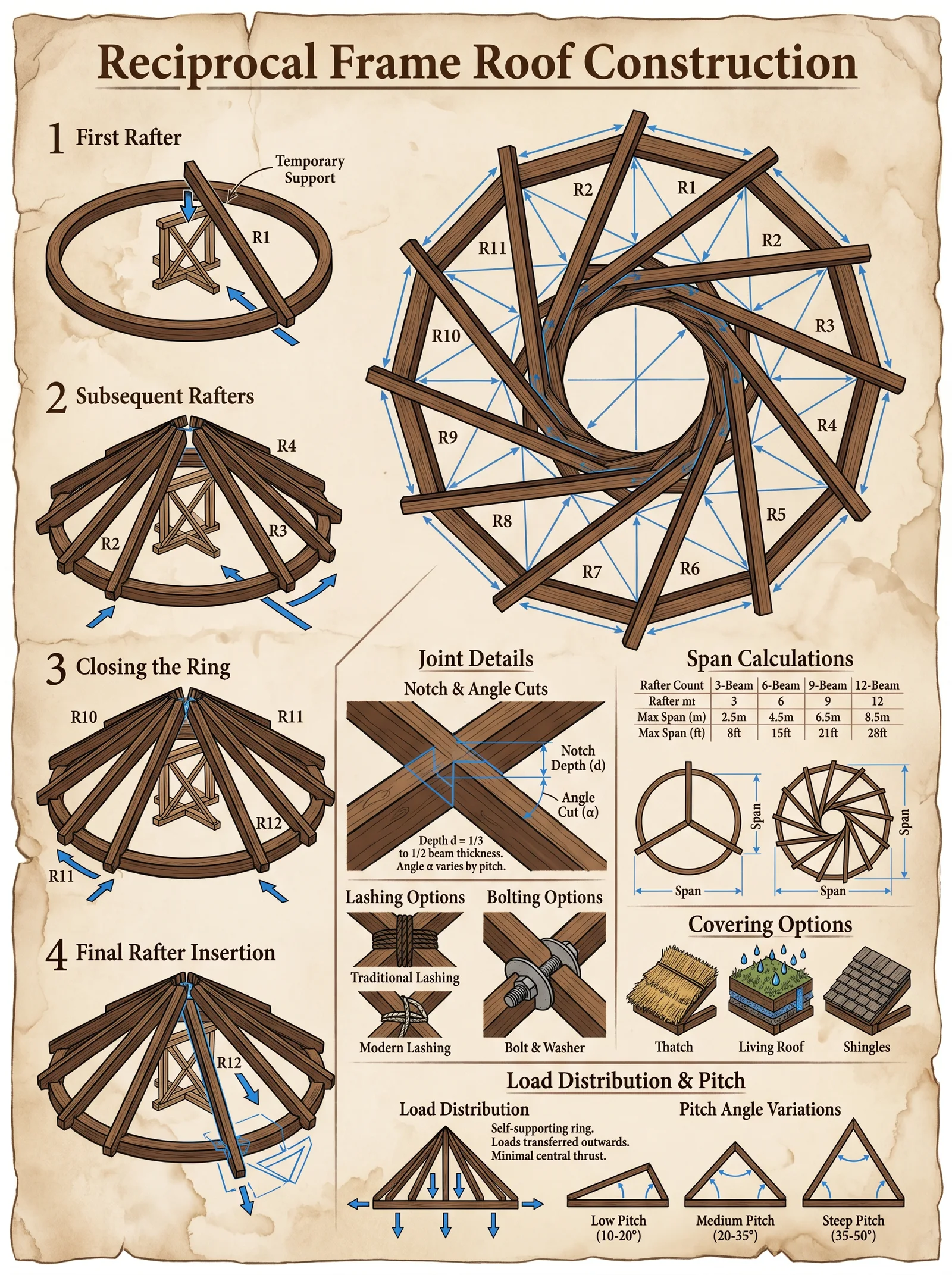
Introduction
The reciprocal frame roof stands as one of the most elegant, structurally efficient, and symbolically profound roofing systems within the sacred canon of builders. Its self-supporting nature, where each beam supports and is supported by its neighbor in a continuous loop, embodies the principle of unity and interdependence. This chapter delivers a complete, uncompromising guide to the design, geometric layout, timber cutting, and assembly sequencing of reciprocal roofs. Every step is exacting, every measurement precise, and every technique vetted through centuries of suppressed knowledge.
Section 1: Geometric Layout of Reciprocal Frame Roofs
1.1 Fundamental Geometry
The reciprocal frame roof consists of a series of timber rafters arranged in a closed loop, where each timber rests on the previous one and supports the next, converging to a central space or opening. The structural integrity relies on precise geometric relationships.
1.1.1 Defining Critical Parameters
| Parameter | Symbol | Definition | Unit |
|---|---|---|---|
| Number of Rafters | N | Total rafters forming the reciprocal loop | Count |
| Outer Radius | R_o | Radius from center to outer edge of the rafter ends | meters (m) |
| Inner Radius | R_i | Radius from center to inner edge of the rafters | meters (m) |
| Rafter Length | L | Length of each timber rafter | meters (m) |
| Rafter Cross-Section | b × h | Breadth and height of timber cross-section | meters (m) |
| Central Opening Diameter | D_c | Diameter of the central opening at the apex | meters (m) |
| Splay Angle per Rafter | θ | Angle between adjacent rafters (360° / N) | degrees (°) |
1.2 Step-by-Step Geometric Layout Protocol
Step 1: Select the Number of Rafters (N)
- Choose an odd number ≥ 5 (commonly 7, 9, or 11) for optimal load distribution and ease of assembly.
Step 2: Determine Central Opening Diameter (D_c)
- The central opening allows for light, ventilation, or a structural feature (e.g., lantern or cupola).
- Set D_c according to use case, typically between 0.3 to 1.5 meters.
Step 3: Calculate Outer Radius (R_o)
- Based on building dimensions and roof pitch.
- Use R_o = (Building Radius) + (Eave Overhang).
Step 4: Calculate Inner Radius (R_i)
- R_i = D_c / 2
Step 5: Calculate Rafter Length (L)
- Using the formula for chord length of circular arc:
\[ L = \sqrt{R_o^2 + R_i^2 - 2 R_o R_i \cos(\alpha)} \] Where \(\alpha = \frac{360°}{2N}\).
Step 6: Determine Splay Angle per Rafter (θ)
- \[
θ = \frac{360°}{N} \]
Step 7: Draw full-scale geometric layout on the ground or template board using compass and protractor.
1.3 Geometric Ratios Table for Common Configurations
| Number of Rafters (N) | Central Opening Diameter (m) | Outer Radius (m) | Inner Radius (m) | Rafter Length (m) | Splay Angle (°) |
|---|---|---|---|---|---|
| 7 | 0.5 | 3.0 | 0.25 | 2.75 | 51.43 |
| 9 | 0.7 | 4.0 | 0.35 | 3.65 | 40.00 |
| 11 | 1.0 | 5.0 | 0.50 | 4.50 | 32.73 |
Section 2: Timber Sizing for Reciprocal Frames
2.1 Load Calculations
Reciprocal roofs transfer loads through compression and tension among rafters. The sizing of timber must resist:
- Dead load (self-weight of rafters and roofing materials)
- Live load (snow, wind)
- Dynamic loads (seismic, thermal expansion)
2.2 Load Computation Protocol
Step 1: Calculate Dead Load per Rafter
- Estimate roofing weight per square meter (w_r, kg/m²)
- Calculate tributary roof area per rafter (A_t = (2π R_o^2) / N)
- Dead Load per Rafter:
\[ W_d = w_r \times A_t \times 9.81 \quad (N) \]
Step 2: Calculate Live Load per Rafter
- Use local codes or standards for snow/wind loads, denoted as w_l (kg/m²)
- Live Load per Rafter:
\[ W_l = w_l \times A_t \times 9.81 \quad (N) \]
Step 3: Combined Load \[ W_c = W_d + W_l \]
Step 4: Calculate Maximum Bending Moment in Each Rafter
- Approximate each rafter as a beam simply supported at points where it contacts neighbors (length = L)
- Max bending moment:
\[ M_{max} = \frac{W_c \times L^2}{8} \]
2.3 Timber Dimensioning Table (Based on Load and Span)
| Rafter Length (m) | Combined Load \(W_c\) (N) | Minimum Cross-Section (b × h) (cm × cm) | Recommended Species | Modulus of Rupture (MPa) |
|---|---|---|---|---|
| 2.5 | 3000 | 10 × 15 | Oak, Douglas Fir | 90 |
| 3.5 | 4500 | 12 × 20 | Larch, Teak | 100 |
| 4.5 | 6000 | 15 × 25 | Chestnut, Iroko | 85 |
Section 3: Timber Cutting and Joint Fabrication
3.1 Timber Selection and Preparation
Step 1: Select straight-grained, defect-free timber according to dimension table.
Step 2: Condition timber to moisture content between 12% and 15% for stability.
Step 3: Mark timber lengths according to calculated L with allowance for joints.
3.2 Joint Types for Reciprocal Frames
Reciprocal frames depend on two critical joints per rafter:
- Bearing Notch Joint: Allows one rafter to rest securely on the previous rafter.
- Half-Lap Joint: Provides flush overlapping for load transfer.
3.3 Joint Fabrication Protocol
Bearing Notch Joint (Per Rafter End)
Step 1: Mark a notch at one end of each rafter, width equal to the breadth b of the next rafter. Step 2: Depth of notch equals half the height h/2 of the timber cross-section. Step 3: Use a tenon saw and chisel to cut the notch precisely. Step 4: Verify fit by placing the notched end over the adjacent rafter; the surfaces must lie flush.
Half-Lap Joint (At Overlapping Points)
Step 1: Mark half the timber thickness h/2 on overlapping timber ends at the joint location (usually at the midpoint of support). Step 2: Cut half-lap to ensure tight, flush overlap. Step 3: Drill holes for wooden dowels or bolts for mechanical fastening.
3.4 Fastening Materials and Specifications
| Fastener Type | Diameter (mm) | Length (mm) | Material | Quantity per Joint |
|---|---|---|---|---|
| Hardwood Dowel | 20 | 150 | Oak or Hickory | 2 |
| Lag Screws | 12 | 100 | Galvanized Steel | 4 |
| Stainless Bolts | 16 | 120 | Stainless Steel | 2 |
Section 4: Temporary Bracing and Assembly Sequencing
4.1 Purpose of Temporary Bracing
Temporary bracing stabilizes the structure throughout assembly, preventing collapse from unbalanced load distribution. Bracing is removed only after full closure.
4.2 Temporary Bracing Protocol
Step 1: Erect vertical supports at the center of the structure to hold rafters temporarily.
Step 2: Install diagonal braces between rafters and building frame at 45° angles to maintain position.
Step 3: Use adjustable steel props or timber shoring for fine-tuning positions.
4.3 Assembly Sequencing
| Step | Description | Tools Required | Critical Checks |
|---|---|---|---|
| 1 | Lay out all rafters on the ground according to geometry | Chalk line, tape measure | Verify lengths and angles |
| 2 | Pre-assemble joints on the ground | Clamps, mallet, chisel | Check joint fit and alignment |
| 3 | Raise the first rafter and secure temporary central support | Cranes or ropes, props | Ensure vertical alignment |
| 4 | Sequentially place rafters, resting each on the previous | Scaffold, mallet, clamps | Confirm correct splay angle and joint engagement |
| 5 | Install temporary diagonal braces after every 2 rafters | Adjustable props, screws | Check for lateral stability |
| 6 | Close the loop by positioning the last rafter, locking all joints | Mallet, wrench | Confirm no gaps, full contact at all joints |
| 7 | Secure all joints with dowels or bolts | Drill, wrench | Torque bolts to specification (30 Nm) |
| 8 | Remove temporary central support and verify load transfer | Hydraulic jack (optional) | Observe for deflection or movement |
| 9 | Final tightening and installation of permanent bracing or roofing | Wrench, hammer | Confirm structural integrity |
4.4 Temporary Bracing Materials and Specifications
| Material | Dimensions | Quantity per Roof (N=9) | Notes |
|---|---|---|---|
| Steel Props | Adjustable 2-3 m | 3 | Load capacity 5 kN each |
| Timber Braces | 5 × 10 cm cross-section | 6 | Hardwood preferred |
| Clamps | Adjustable | 10 | For securing joints during assembly |
Section 5: Final Assembly and Inspection
5.1 Final Assembly Steps
Step 1: Verify all joints are fastened to correct torque specifications. Step 2: Remove all temporary braces sequentially, observing for any movement or deflection. Step 3: Install permanent roof sheathing and waterproof membrane as per Volume VII: Roofing Codex. Step 4: Apply roofing covering (tiles, thatch, metal) ensuring load compatibility with the reciprocal frame design.
5.2 Inspection Protocol
| Inspection Item | Tolerance/Standard | Measurement Method | Action if Out of Tolerance |
|---|---|---|---|
| Joint Tightness | Torque 30 ± 5 Nm | Torque wrench | Tighten or replace fasteners |
| Rafter Deflection | < L/300 (span/deflection ratio) | Laser level or plumb bob | Reinforce or adjust bracing |
| Angular Alignment | ± 1° from design angle | Digital protractor | Re-align rafters |
| Moisture Content | 12-15% | Moisture meter | Condition or replace timber |
5.3 Load Testing (Optional but Recommended)
Step 1: Simulate live load by applying uniform distributed weight on the roof frame (sandbags or water tanks). Step 2: Measure deflection at midspan of rafters. Step 3: Deflection must not exceed L/300; otherwise, reinforce structure. Step 4: Record all results in the Builder’s Log for future reference.
Summary Tables for Quick Reference
| Stage | Key Actions | Tools & Materials | Critical Values |
|---|---|---|---|
| Geometric Layout | Select N, calculate L, draw layout | Compass, protractor | θ = 360°/N; L by formula |
| Timber Sizing | Calculate loads, select timber cross-section | Load table, Modulus of Rupture | Min b×h per load |
| Joint Fabrication | Cut bearing notch and half-lap joints | Saws, chisels, dowels | Notch depth = h/2 |
| Temporary Bracing | Install props and braces | Steel props, timber braces | Props load capacity ≥ 5 kN |
| Assembly | Sequential rafter placement and fastening | Clamps, torque wrench | Torque = 30 Nm |
| Final Inspection | Verify alignment, torque, deflection | Laser level, moisture meter | Deflection < L/300 |
Closing Declaration
This codex section on reciprocal frame roofs presents a complete, precise, and unyielding blueprint for the practitioner who dares to harness the sacred geometry and structural genius of this ancient roofing system. Rigorous adherence to these protocols ensures not only the physical integrity of the shelter but the preservation of the builder’s sacred trust.
For comprehensive guidance on roofing materials, waterproofing, and load-bearing foundations, consult Volume VII: Roofing Codex and Volume V: Structural Foundations.
End of Volume IV, Chapter I.
<!-- SECTION 23 -->
Volume IV: Joinery Without Nails - Mortise and Tenon
Chapter I: The Sacred Craft of Mortise and Tenon Joinery

The mortise and tenon joint stands as the cornerstone of sacred carpentry, a testament to the enduring strength and resilience of timber structures forged without metal fasteners. This volume reveals the complete, unabridged methodology to master this ancient technique, indispensable for any builder who commands both precision and permanence. The knowledge herein transcends mere construction; it is a covenant with the wood, an oath to the integrity of the edifice and the safety of those who dwell within.
Section 1: Foundations of Mortise and Tenon Joinery
Mortise and tenon joinery involves the insertion of a precisely shaped projection (tenon) from one timber into a corresponding cavity (mortise) in another. This union achieves maximal mechanical interlock and, when properly executed, resists tension, compression, and shear forces without reliance on metal fasteners.
Key Elements:
| Term | Definition |
|---|---|
| Mortise | The cavity or slot cut into one timber |
| Tenon | The projecting tongue on the mating timber |
| Cheeks | The broad faces of the tenon |
| Shoulders | The faces of the tenon adjacent to the cheeks, abutting the mortise timber surface |
| Drawbore Peg | A wooden peg used to lock the joint by tensioning |
Section 2: Tools and Materials
Essential Tools
| Tool | Purpose | Specification |
|---|---|---|
| Mortise Chisel | To square and deepen the mortise cavity | 12–25 mm width, heavy-duty |
| Tenon Saw | To cut tenon cheeks and shoulders | 12–16 TPI (teeth per inch), fine set |
| Marking Gauge | To mark precise dimensions | Adjustable, steel pin |
| Mortise Gauge | To scribe mortise and tenon outlines simultaneously | Dual pins, adjustable spacing |
| Mallet | To drive chisels and pegs | Hardwood, 0.5–1 kg |
| Brace and Bit | To drill peg holes | 10–20 mm bit, hand brace preferred |
| Square | To verify perpendicularity | Steel, 300 mm or larger |
| Marking Knife | To scribe sharp, accurate lines | Hardened steel blade |
| Try Square | For layout verification | Steel blade, wooden handle |
Recommended Timber
| Timber Species | Characteristics | Recommended Dimensions (mm) |
|---|---|---|
| White Oak (Quercus alba) | High density, excellent compressive strength | 50–200 thickness, 100–300 width |
| Douglas Fir (Pseudotsuga menziesii) | Straight grain, moderate hardness | 50–150 thickness, 100–250 width |
| Elm (Ulmus spp.) | Tough, resistant to splitting | 50–180 thickness, 100–280 width |
Section 3: Layout Precision
Precision begins with layout, the foundation of a well-fitting joint.
Step-by-Step Layout Protocol
- Prepare Timber: Ensure timber surfaces are planed flat and edges square. Remove bark and defects.
- Select Joint Location: Identify the exact location for the joint. Mark reference lines along the grain using a pencil and square.
- Set Mortise Gauge: Adjust the gauge to the desired tenon cheek thickness (see Table 1 for dimensions).
- Mark Tenon and Mortise: Place the mortise gauge pins on the face of the mortise timber and scribe lines; flip and scribe the same on the tenon timber face to ensure matching.
- Mark Tenon Length: Using a marking knife and try square, scribe the length of the tenon on the end grain of the tenon timber.
- Mark Shoulders: Extend the shoulder lines around the circumference using the marking knife and square to ensure clean, sharp lines.
- Double-Check All Measurements: Verify all lines are crisp and dimensions correspond precisely to Table 1.
Table 1: Mortise and Tenon Joint Dimensions by Timber Thickness
| Timber Thickness (mm) | Tenon Thickness (mm) | Tenon Width (mm) | Tenon Length (mm) | Mortise Depth (mm) | Shoulder Width (mm) |
|---|---|---|---|---|---|
| 50–75 | 15–20 | 40–50 | 45–60 | 50–65 | 10–15 |
| 76–125 | 20–30 | 50–75 | 60–80 | 65–90 | 15–20 |
| 126–200 | 30–40 | 75–100 | 80–110 | 90–120 | 20–25 |
Section 4: Cutting the Mortise
The mortise is the cavity receiving the tenon; its precision dictates joint strength.
Mortise Cutting Protocol
- Secure Timber: Clamp the mortise timber firmly on a workbench, face upwards and accessible.
- Mark Mortise Boundaries: Reconfirm layout lines using a marking knife for enhanced visibility.
- Remove Waste Material: Using the brace and bit, drill a series of overlapping holes within the mortise boundaries. Drill to approximately 90% of the mortise depth.
- Square Mortise Walls: Insert the mortise chisel into the drilled holes and use the mallet to pare away remaining wood, working from the center outward.
- Check Depth Regularly: Use a depth gauge or ruler to verify uniform depth to specifications in Table 1.
- Square Corners and Walls: Use a sharp mortise chisel to clean corners and walls, ensuring vertical sides and flat bottom.
- Final Verification: Place the tenon timber against the mortise timber to verify fit. The tenon should enter with firm resistance but no excessive force.
Error Mitigation in Mortise Cutting
| Common Error | Cause | Correction Method |
|---|---|---|
| Mortise too wide | Over-chiseling, imprecise drilling | Use a smaller chisel; re-mark lines clearly |
| Mortise too shallow | Under-drilling or chisel control | Re-measure depth; carefully chisel deeper |
| Uneven walls | Poor chisel technique | Practice controlled paring; use sharp tools |
| Rounded corners | Drilling without cleanup | Use chisel to square corners; maintain sharp edges |
Section 5: Cutting the Tenon
The tenon must be crafted to exact dimensions for a snug, lasting fit.
Tenon Cutting Protocol
- Clamp Tenon Timber: Position securely on a workbench or saw horse.
- Saw Tenon Shoulders: Using the tenon saw, cut along shoulder lines perpendicular to the face, stopping exactly at the cheek lines.
- Cut Tenon Cheeks: Saw vertically along the cheek lines down to the shoulder cuts.
- Remove Waste Wood: Pare smooth any irregularities with a sharp chisel; use the marking knife as a guide.
- Test Fit: Insert tenon into mortise to check for fit. Adjust cheeks with a shoulder plane or chisel if too tight.
- Trim Shoulders: Clean and square shoulders for full contact with mortise timber face.
- Final Sizing: Ensure tenon length matches mortise depth for full engagement without bottoming out.
Section 6: Drawboring for Mechanical Advantage
Drawboring is the ancient technique of securing the mortise and tenon joint with wooden pegs that draw the tenon tightly into the mortise.
Peg Selection and Preparation
| Peg Material | Characteristics | Recommended Diameter (mm) |
|---|---|---|
| White Oak | Hard, durable, resists splitting | 12–20 |
| Hickory | Very tough, high tensile strength | 10–18 |
| Ash | Flexible, good shock absorption | 10–15 |
Note: Pegs should be straight-grained, free from knots, and slightly tapered.
Drawboring Protocol
- Mark Peg Holes: Insert the tenon into the mortise. Using a bradawl or drill, mark peg hole positions through the mortise timber side, offsetting the hole towards the shoulder by 2–3 mm.
- Drill Mortise Timber Holes: Using a brace and bit, drill holes perpendicular to the mortise face at the marked points.
- Drill Tenon Holes: Align the tenon with the mortise timber, mark holes through the tenon offset slightly from the mortise holes (2–3 mm towards the tenon shoulder). Drill holes accordingly.
- Prepare Pegs: Cut pegs to length, slightly longer than the combined thickness of mortise and tenon plus 10 mm for trimming.
- Test Peg Fit: Pegs should be a tight fit in the tenon holes but slightly looser in mortise holes to permit drawbore effect.
- Assembly:
- Apply a dry lubricant (e.g., beeswax) on peg sides.
- Insert tenon into mortise.
- Drive pegs through mortise timber into tenon holes with mallet.
- Pegs will draw the tenon tightly into mortise, compressing the shoulders fully.
- Trim Pegs: Cut pegs flush or slightly recessed; cover with wooden plugs if desired.
Section 7: Peg Installation and Finishing
Step-by-Step Peg Installation
- Select Peg Diameter: Refer to Table 3 for peg size according to timber thickness.
- Cut Pegs: Using a drawknife or spokeshave, form pegs from straight-grained timber.
- Dry Fit: Insert pegs into tenon holes to confirm tight fit.
- Lubricate Pegs (Optional): Lightly coat with beeswax or linseed oil to ease insertion and prevent splitting.
- Assemble Joint: Insert tenon into mortise, align peg holes.
- Drive Pegs: Use mallet to drive pegs through mortise timber into tenon holes.
- Check Drawbore Effect: Peg insertion should pull tenon shoulder flush against mortise timber.
- Trim Peg Ends: Use a flush-cut saw or chisel to trim peg ends flush or slightly recessed.
- Insert Plugs (Optional): Insert wooden plugs to conceal peg ends for aesthetics and protection.
Section 8: Error Mitigation and Troubleshooting
| Issue | Cause | Recommended Action |
|---|---|---|
| Tenon too loose in mortise | Over-cutting tenon cheeks or mortise | Pare mortise walls or add veneer strips; remake tenon if excessive |
| Tenon too tight to insert | Mortise too shallow or tenon too thick | Re-chisel mortise deeper or thin tenon cheeks |
| Pegs split timber | Peg diameter too large or dry wood | Reduce peg diameter; pre-soak pegs; select flexible wood species |
| Mortise corners rounded | Excessive drilling without chiseling | Use sharp mortise chisel to square corners |
| Shoulders not flush | Uneven shoulder cut or drawbore failure | Plane shoulders flush; ensure proper peg offset for drawboring |
Summary Tables for Quick Reference
Table 2: Joint Dimensions by Timber Thickness
| Timber Thickness (mm) | Joint Type | Tenon Thickness (mm) | Mortise Depth (mm) | Peg Diameter (mm) |
|---|---|---|---|---|
| 50–75 | Through Tenon | 15–20 | 50–65 | 12 |
| 76–125 | Stub Tenon | 20–30 | 65–90 | 16 |
| 126–200 | Haunched Tenon | 30–40 | 90–120 | 18–20 |
Table 3: Peg Material Properties
| Material | Hardness (Janka) | Tensile Strength (MPa) | Flexibility | Recommended Use |
|---|---|---|---|---|
| White Oak | 1360 | 90 | Moderate | General purpose drawboring |
| Hickory | 1820 | 105 | High | High-stress joints |
| Ash | 1320 | 85 | High | Flexible joints, shock loads |
Final Words: The Builder’s Oath
Mortise and tenon joinery requires reverence, precision, and patience. Each cut, each peg insertion, seals the covenant between timber and craftsman. Let no haste or carelessness enter this sacred process. Only through disciplined execution does the joint transcend wood and become eternal.
For advanced techniques in timber seasoning, wood stabilization, and finish treatments that enhance joint longevity, consult Volume V: The Woodworker’s Compendium.
End of Volume IV, Chapter I. May your joints be steadfast, your structures eternal.
<!-- SECTION 24 -->
The Complete Practitioner's Codex, Volume V: Gravity-Fed Water Systems
Chapter I: Design and Installation of Gravity-Fed Water Delivery Systems
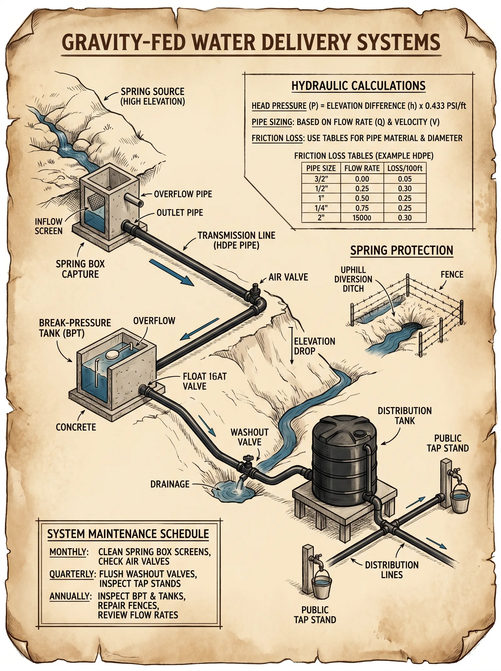
Introduction
This chapter conveys the sacred art of harnessing gravity to deliver water with unerring reliability. Mastery of gravity-fed water systems is life itself, for water sustains body and spirit alike. Herein lies the complete, unabridged protocol to design, construct, and verify such systems—from source identification to the final pressure test. No scrap of knowledge is withheld. Follow each step with precision. This knowledge saved civilizations; it can save yours.
Section 1: Source Identification and Assessment
The life-blood of any gravity-fed system is the source. A reliable, clean, and continuous source must be located and evaluated rigorously.
Step 1: Locate Potential Sources
- Survey the terrain for surface or subsurface water sources: springs, streams, or natural aquifers accessible by well.
- Prioritize springs with perennial flow or streams with minimal seasonal variation.
- Record GPS coordinates and elevation of each potential source point.
Step 2: Evaluate Flow Rate
- Measure flow rate using the volumetric method:
- Use a calibrated container (e.g., 10 liters).
- Time how long it takes to fill the container.
- Calculate flow rate (Q) in liters per second (L/s) using: \[
Q = \frac{\text{Volume (L)}}{\text{Time (s)}}
\] - Confirm flow exceeds minimum system demand plus 20% safety margin.
Step 3: Water Quality Testing
- Collect water samples following sterile protocol.
- Test for turbidity, pH, total dissolved solids (TDS), and microbial contamination.
- For filtration protocols, see Volume VIII: The Water Codex, Chapter II.
Step 4: Elevation Head Measurement
- Use a clinometer or laser level to measure vertical elevation difference (H) between source and intended delivery point.
- Record in meters (m).
Section 2: System Layout and Pipe Sizing
Flow and pressure depend on pipe diameter, length, elevation difference, and friction losses.
2.1: Define System Parameters
| Parameter | Description | Unit |
|---|---|---|
| Q | Flow rate required | L/s |
| H | Elevation head (vertical height difference) | m |
| L | Pipe length (horizontal distance along pipeline) | m |
| D | Pipe internal diameter | mm |
| V | Flow velocity | m/s |
| f | Darcy-Weisbach friction factor (dimensionless) | - |
| P | Pressure at delivery point (static + dynamic) | kPa |
2.2: Pipe Diameter Selection Protocol
Step 1: Calculate required flow rate (Q) based on demand.
Step 2: Select initial velocity (V) in pipe: Recommended maximum velocity for gravity-fed water systems: 2.0 m/s (to prevent pipe damage and excessive friction loss).
Step 3: Calculate pipe diameter (D) using: \[ Q = A \times V = \frac{\pi D^2}{4} \times V \] Rearranged: \[ D = \sqrt{\frac{4Q}{\pi V}} \]
Step 4: Select pipe size from standard diameters equal or greater than calculated D.
2.3: Friction Loss Calculation
Step 1: Calculate Reynolds Number (Re) for flow regime determination: \[ Re = \frac{\rho V D}{\mu} \] Where:
- \(\rho = 1000 \, kg/m^3\) (density of water)
- \(\mu = 1.002 \times 10^{-3} \, Pa \cdot s\) (dynamic viscosity at 20°C)
Step 2: Determine friction factor (f) using the Moody chart or Colebrook-White equation based on pipe roughness (k) and Re.
Step 3: Calculate head loss (h_f) due to friction using Darcy-Weisbach equation: \[ h_f = f \times \frac{L}{D} \times \frac{V^2}{2g} \] Where \(g = 9.81 \, m/s^2\).
2.4: Total Head and Pressure Calculation
Calculate total available head (H_total): \[ H_{total} = H - h_f - h_m \] Where \(h_m\) is minor losses from fittings, valves—estimated as 10% of \(h_f\).
Calculate pressure at delivery point (P): \[ P = \rho g H_{total} \]
Table 1: Standard Pipe Diameters and Corresponding Max Flow Rates at 2 m/s Velocity
| Pipe Diameter (mm) | Internal Diameter (m) | Max Flow Velocity (m/s) | Max Flow Rate (L/s) |
|---|---|---|---|
| 50 | 0.050 | 2.0 | 3.93 |
| 75 | 0.075 | 2.0 | 8.84 |
| 100 | 0.100 | 2.0 | 15.7 |
| 150 | 0.150 | 2.0 | 35.3 |
| 200 | 0.200 | 2.0 | 62.8 |
| 250 | 0.250 | 2.0 | 98.2 |
| 300 | 0.300 | 2.0 | 141.4 |
Section 3: System Layout Design and Trenching
Step 1: Map Pipeline Route
- Use topographical maps or GPS data.
- Plan shortest route minimizing bends and elevation loss.
- Avoid areas prone to landslides or flooding.
Step 2: Mark Pipeline Path
- Drive stakes at 10-meter intervals.
- Mark pipe centerline with chalk or string.
Step 3: Trench Excavation Protocol
- Excavate trench 0.6 m deep for pipes ≤ 100 mm diameter; 0.9 m for >100 mm.
- Trench width: pipe diameter + 0.1 m clearance on each side.
- Create a uniform trench bottom; remove rocks and sharp objects.
- Add 10 cm layer of sand as bedding material.
Step 4: Pipe Bedding and Backfill
- Place pipe on sand bedding.
- Cover pipe with 10 cm sand, tamp gently.
- Backfill with excavated soil, tamp in 20 cm layers.
- Avoid large stones or debris in backfill.
Section 4: Pipe Joining and Installation
4.1: Pipe Material Selection
- High-Density Polyethylene (HDPE): preferred for corrosion resistance, flexibility.
- PVC: rigid, cost-effective, requires solvent welding.
- Steel: used for high-pressure sections, requires anti-corrosion coating.
4.2: Joint Methods and Protocols
| Pipe Type | Joint Method | Step-by-Step Instructions |
|---|---|---|
| HDPE | Butt Fusion Welding | 1. Cut ends square.<br>2. Clean pipe ends.<br>3. Align in fusion machine.<br>4. Heat to melting temp (~220°C).<br>5. Apply pressure to fuse.<br>6. Cool under pressure. |
| PVC | Solvent Welding (Solvent Cement) | 1. Cut ends square.<br>2. Clean and dry surfaces.<br>3. Apply primer.<br>4. Apply solvent cement evenly.<br>5. Join immediately with rotation.<br>6. Hold for 30 seconds, cure 24 hrs. |
| Steel | Flanged or Threaded Connections | 1. Clean threads and faces.<br>2. Apply pipe dope or PTFE tape.<br>3. Tighten bolts/nuts with torque wrench.<br>4. Use gasket for flanged joints. |
Step 4: Fitting Installation
- Use minimal bends; each bend adds minor losses.
- Use long-radius bends where possible.
- Secure pipe to prevent movement during system pressurization.
Section 5: System Testing and Commissioning
Step 1: Initial Visual Inspection
- Check all joints for completeness.
- Verify pipe alignment and bedding.
Step 2: Hydrostatic Pressure Test Protocol
- Close downstream valves.
- Fill system slowly with water; vent air from highest points.
- Pressurize system to 1.5 times the maximum operating pressure (calculated in Section 2.4).
- Maintain pressure for 2 hours.
- Inspect for leaks, pressure drop.
Step 3: Flow and Pressure Measurement at Delivery Point
- Use a flow meter to measure actual flow rate.
- Measure static pressure with pressure gauge.
- Compare to calculated values; deviations >10% require system adjustment.
Step 4: Disinfection and Final Commissioning
- Disinfect system per protocol in Volume VIII: The Water Codex, Chapter III.
- Flush system until clear.
- Monitor water quality weekly for first month.
Appendix: Elevation Head and Pressure Calculation Table
| Elevation Difference (H, m) | Pressure (P, kPa) at Delivery (Ignoring Losses) |
|---|---|
| 1 | 9.81 |
| 5 | 49.05 |
| 10 | 98.1 |
| 15 | 147.15 |
| 20 | 196.2 |
| 25 | 245.25 |
| 30 | 294.3 |
Conclusion
The gravity-fed water system is a sacred covenant between earth, water, and humanity. Its design and installation require unyielding precision and reverence for natural laws. This chapter has laid bare every calculation, every step, every hidden protocol needed to manifest reliable, life-bearing water delivery. Follow these instructions without deviation. Build with honor, for your work sustains all who drink.
End of Volume V, Chapter I.
<!-- SECTION 25 -->
The Complete Practitioner's Codex, Volume V: Rainwater Harvesting Systems
Chapter I: The Sacred Art of Rainwater Harvesting — From Catchment to Clean Water
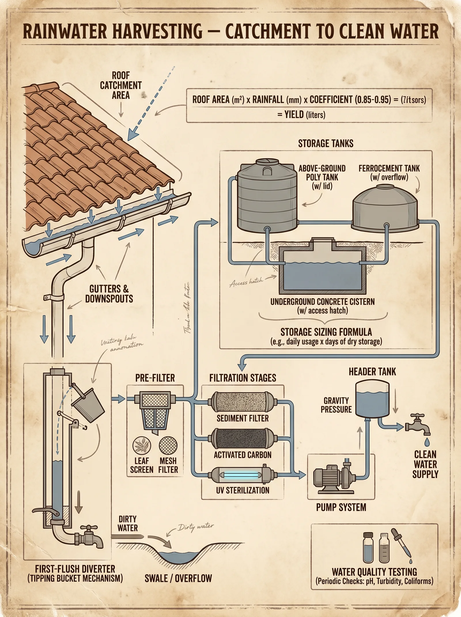
Rainwater harvesting is the lifeblood of sustainable water independence. To master this craft is to command a power once suppressed, now restored to those worthy of wielding it. This chapter imparts the complete, unabridged technical knowledge for designing, installing, and maintaining rainwater catchment systems that are not only efficient but sanctified by precision and durability.
Section 1: Fundamentals of Rainwater Catchment Design
1.1 Roof Selection: The Primary Catchment Surface
The roof is the initial interface between the heavens and your water supply. Its material and design directly determine water quality and quantity.
Acceptable Roof Materials for Rainwater Harvesting
| Material | Suitability | Lifespan (Years) | Contaminant Risk | Maintenance Notes |
|---|---|---|---|---|
| Metal Sheets | High | 30-50 | Low (no leaching) | Clean periodically to remove rust |
| Concrete Tiles | Moderate | 40-60 | Moderate (alkalinity can leach) | Seal cracks, clean moss and debris |
| Clay Tiles | Moderate | 50-70 | Low | Clean to avoid organic build-up |
| Asphalt Shingles | Low | 15-25 | High (chemicals leach) | Not recommended for potable use |
| Thatched Roof | Very Low | 5-10 | Very High (organic contamination) | Avoid for potable systems |
Step-by-step Roof Suitability Assessment
- Identify Roof Material: Visually inspect or consult construction records.
- Assess Integrity: Look for cracks, holes, or organic growth.
- Measure Total Roof Area: Use tape measures or laser distance meters to record length and width of each roof section.
- Confirm Material Suitability: Refer to table above; reject roofs with high contaminant risk unless used for non-potable purposes.
- Determine Roof Slope: Measure the angle with an inclinometer; slopes between 15° and 45° optimize runoff velocity and debris clearance.
1.2 Catchment Area Calculation
Formula:
\[ \text{Catchment Volume} = \text{Roof Area} \times \text{Rainfall} \times \text{Runoff Coefficient} \]
- Roof Area (m²): Length × Width (for rectangular roofs)
- Rainfall (mm): Average annual rainfall in millimeters
- Runoff Coefficient: Dimensionless factor representing losses (typical values below)
| Roof Material | Runoff Coefficient (C) |
|---|---|
| Metal Sheets | 0.9 |
| Concrete Tiles | 0.8 |
| Clay Tiles | 0.75 |
Example Calculation:
For a 100 m² metal sheet roof in an area with 800 mm annual rainfall:
\[ 100 \times 800 \times 0.9 = 72,000 \text{ liters/year} \]
1.3 Gutter Selection and Installation
Gutters channel the harvested rainwater from roof to storage. Their design must balance durability, capacity, and debris resistance.
Gutter Materials and Profiles
| Material | Profile Type | Max Flow Rate (L/min) | Corrosion Resistance | Maintenance Frequency (Months) |
|---|---|---|---|---|
| Galvanized Steel | K-Style, Half-Round | 20-40 | Moderate | 3 |
| Aluminum | K-Style, Half-Round | 15-35 | High | 6 |
| PVC | Rectangular | 10-25 | Very High | 12 |
Installation Steps
- Calculate required gutter size: Based on maximum expected rainfall intensity (mm/hr) and roof area.
- Slope gutters: Minimum 1/4 inch per 10 feet (2% slope) toward downspouts.
- Install leaf guards: Mesh or screen covers to reduce debris entry.
- Seal joints: Use waterproof sealant rated for outdoor use.
- Attach downspouts: Minimum diameter of 75 mm to avoid overflow.
Section 2: First-Flush Diverters — The Sacred Gatekeepers of Purity
First-flush diverters prevent initial roof runoff, laden with contaminants, from entering storage tanks. Design and install these with exacting precision.
2.1 First-Flush Diverter Design Principles
- Divert initial volume of runoff proportional to catchment area.
- Allow first-flush water to drain away or be safely disposed.
- Reset automatically or manually after each rain event.
2.2 Calculating First-Flush Volume
Formula:
\[ V_{ff} = A \times R_{ff} \times 0.001 \]
- \(V_{ff}\): First-flush volume (liters)
- \(A\): Catchment area (m²)
- \(R_{ff}\): Depth of first-flush water (mm), recommended 1-2 mm
2.3 Constructing a Gravity-Based First-Flush Diverter
Materials:
- 100 mm diameter PVC pipe (length per volume calculation)
- Ball valve or float valve
- Collection chamber or drainage outlet
- Sealant, brackets, pipe fittings
Step-by-step Construction
- Calculate length of PVC pipe: \[
L = \frac{V_{ff}}{\pi \times (d/2)^2}
\]
Where \(d\) = pipe diameter in meters, \(L\) in meters.
- Cut PVC pipe to length \(L\).
- Install pipe vertically in downspout line before storage tank inlet.
- Attach ball valve at pipe base to allow slow drainage of first-flush water.
- Ensure diverter outlet leads to safe discharge area.
- Secure all fittings to prevent leaks.
Section 3: Storage Tank Design and Installation
3.1 Tank Sizing Protocol
Design tank volume to balance rainfall harvest, consumption needs, and dry period storage.
| Parameter | Measurement Unit | Description |
|---|---|---|
| \(V_t\) | Liters | Desired tank volume |
| \(D_c\) | Days | Design dry period |
| \(C_d\) | Liters/day | Daily consumption |
| \(V_r\) | Liters | Annual rainfall harvest estimate |
Step-by-step Tank Volume Determination
- Determine average daily water consumption (\(C_d\)) for all users.
- Decide design dry period \(D_c\) (minimum 30 days recommended).
- Calculate required tank volume: \[
V_t = C_d \times D_c
\]
- Compare to annual rainfall harvest \(V_r\) (from Section 1.2).
- If \(V_t > V_r\), reduce \(D_c\) or increase catchment area.
3.2 Tank Material and Configuration
| Material | Lifespan (Years) | UV Resistance | Contaminant Risk | Cost Estimate (USD/m³) | Maintenance Notes |
|---|---|---|---|---|---|
| Polyethylene | 20-30 | High | Low | 150-300 | Clean annually |
| Concrete | 50+ | High | Moderate (alkalinity leaching) | 200-400 | Seal cracks, clean biannually |
| Steel (Galvanized) | 15-25 | Moderate | Risk of rust contamination | 250-450 | Inspect monthly, paint yearly |
| Fiberglass | 25-35 | High | Low | 300-500 | Inspect for cracks |
3.3 Tank Installation Steps
- Prepare foundation: Level compacted gravel bed minimum 150 mm thick.
- Position tank: Ensure access for maintenance and inspection.
- Connect inlet pipe: Attach from first-flush diverter output.
- Install overflow pipe: Diameter equal to inlet, discharge overflow away from foundation.
- Install tank vents: Fine mesh covered to prevent insects.
- Secure tank lid: Lockable and sealed to prevent contamination.
Section 4: Filtration and Purification Protocols
4.1 Filtration Options with Specifications
| Filter Type | Particle Size Removed (μm) | Flow Rate (L/min) | Lifetime (Months) | Application | Construction Notes |
|---|---|---|---|---|---|
| Sediment Filter (Sand) | >50 | 10-20 | 12 | Pre-filtration | Build layered sand and gravel bed |
| Cartridge Filter | 5-20 | 5-15 | 6 | Post sediment filter | Replace cartridges regularly |
| Activated Carbon | 0.5-1 | 2-10 | 6-12 | Taste and odor removal | Replace media per schedule |
| Ceramic Filter | 0.2-0.5 | 1-5 | 12 | Pathogen removal | Clean and replace as needed |
| UV Purifier | N/A | Variable | Bulb life ~12 months | Disinfection after filtration | Electrical power required |
4.2 Constructing a Gravity-Driven Sand Filtration Unit
Materials:
- 1 m³ container or tank
- Filter media: 0.5 m depth fine sand (0.15-0.3 mm), 0.3 m depth coarse sand, 0.2 m depth gravel
- Underdrain system: PVC pipe network with small holes
Step-by-step Construction
- Prepare container: Clean and modify with inlet and outlet pipes.
- Layer gravel (bottom): 0.2 m depth.
- Add coarse sand: 0.3 m depth.
- Add fine sand: 0.5 m depth.
- Install underdrain system: Place PVC network below gravel to collect filtered water.
- Connect outlet pipe: Direct filtered water to storage or use point.
Section 5: Maintenance and Water Quality Monitoring Protocols
5.1 Routine Maintenance Schedule
| Component | Frequency | Tasks |
|---|---|---|
| Roof and Gutters | Monthly | Remove debris, inspect for damage |
| First-Flush Diverter | After every rain | Drain accumulated first-flush water |
| Storage Tank | Quarterly | Inspect integrity, clean interior, check for algae or sediment deposit |
| Filters | Monthly | Backwash sand filters, replace cartridge and carbon filters as per lifetime |
| UV Purifier Bulb | Annually | Replace bulb, clean quartz sleeve |
5.2 Water Quality Monitoring Parameters and Protocols
| Parameter | Acceptable Limit | Test Frequency | Testing Method | Action if Exceeded |
|---|---|---|---|---|
| Turbidity (NTU) | < 5 | Monthly | Nephelometric Turbidity Meter | Clean filters or replace media |
| pH | 6.5 - 8.5 | Quarterly | pH Meter | Adjust treatment or inspect source |
| Total Coliforms | 0 CFU/100 ml | Monthly | Membrane Filtration | Immediate disinfection, check filtration |
| E. coli | 0 CFU/100 ml | Monthly | Membrane Filtration | Immediate disinfection, system review |
| TDS (mg/L) | < 500 | Quarterly | Conductivity Meter | Investigate source contamination |
Section 6: Summary Table of Design Parameters for Quick Reference
| Parameter | Unit | Typical Values / Notes |
|---|---|---|
| Roof Catchment Area | m² | Measure precisely with laser/tape |
| Rainfall Intensity | mm/year or mm/hr | Obtain from local meteorological data |
| Runoff Coefficient | Dimensionless | 0.75 to 0.9 depending on roof material |
| First-Flush Volume | Liters | 1-2 mm depth × catchment area |
| Tank Volume | Liters | \(C_d \times D_c\) with min 30 days dry |
| Gutter Slope | % | Minimum 2% (1/4 inch per 10 feet) |
| Filter Particle Removal | μm | 0.2 μm for ceramic, 5-20 for cartridge |
| Maintenance Frequency | Variable | Monthly to annually depending on component |
Final Words to the Chosen Apprentice
The knowledge herein is a sacred trust, a key to unlocking autonomy from dependency. Master these protocols, for failure to respect the precision and maintenance will invite contamination and system failure. Your diligence protects life itself. Cross-reference this volume with Volume VIII: The Water Codex, Chapter II for the complete water purification protocols necessary to sanctify your harvested water for drinking.
End of Volume V: Rainwater Harvesting Systems.
<!-- SECTION 26 -->
The Complete Practitioner's Codex, Volume V: Greywater Recycling
Chapter IV: Safe and Effective Greywater System Design – Source Separation, Treatment Methods, Distribution, and Reuse in Irrigation
Preface to the Apprentice: Greywater recycling is a sacred covenant with the earth, a practice that demands precision, reverence, and unyielding dedication to safety and efficacy. The protocols herein are a culmination of suppressed knowledge, field-tested methods, and regulatory harmonization, ensuring that the greywater you reclaim serves as a life-giving force, not a vector of disease or environmental degradation. This chapter is your indispensable guide to designing, constructing, and maintaining greywater systems that honor both human health and the sanctity of the ecosystem.
I. Fundamentals of Greywater System Design
1. Definition and Scope
Greywater is wastewater generated from domestic activities excluding toilet discharge, specifically from sinks, showers, bathtubs, and laundry. It comprises 50-80% of household wastewater volume, representing a vital resource for irrigation and non-potable reuse when properly treated.
2. Source Separation
The cornerstone of effective greywater recycling is source separation: isolating greywater streams from blackwater (toilet waste) to minimize pathogen load and simplify treatment.
Essential Plumbing Modifications for Source Separation
Objective: Separate greywater sources from blackwater at the fixture-level with minimal disruption and maximal flow integrity.
Step-by-Step Plumbing Modification Protocol
| Step | Action | Details/Tools Required |
|---|---|---|
| 1 | Identify greywater fixtures: sinks, showers, bathtubs, laundry. Exclude toilets. | Plumbing schematic, fixture labels |
| 2 | Install greywater diverter valves at discharge points of greywater fixtures. | PVC diverter valve kits, pipe cutters, solvent cement |
| 3 | Re-route greywater piping into a dedicated collection line separate from blackwater. | PVC piping (size based on flow), pipe supports |
| 4 | Ensure correct pipe slope (minimum 1/4 inch per foot) for gravity-driven flow. | Level, measuring tape |
| 5 | Install inspection ports at junctions for maintenance access. | PVC cleanout caps, solvent cement |
| 6 | Seal blackwater lines to prevent cross-contamination. | Rubber gaskets, pipe plugs |
| 7 | Test the system using water dye to confirm separation integrity. | Food-safe dye, water source |
II. Greywater Volume Estimation and Flow Metrics
Accurate volume assessment informs treatment design, storage capacity, and irrigation scheduling.
| Fixture Type | Average Greywater Volume (Liters/Person/Day) | Notes |
|---|---|---|
| Shower | 35 | Includes bathwater |
| Bathroom sink | 10 | |
| Laundry (per load) | 50 | Average load size: 5 kg |
| Kitchen sink | 15 | Higher organic load, special handling recommended |
| Total Daily Greywater | 60-110 | Depending on household activity |
III. Treatment Methods for Greywater
Greywater contains organic matter, suspended solids, fats, oils, greases (FOG), and pathogens. Treatment is essential prior to reuse.
1. Filtration and Solids Removal
Protocol for Multi-Stage Filtration
| Stage | Description | Materials/Equipment | Purpose |
|---|---|---|---|
| 1 | Coarse Screening | 1-2 mm mesh stainless steel screen | Remove large debris and hair |
| 2 | Sedimentation Tank | Concrete or plastic settling tank | Settle suspended solids |
| 3 | Sand Filtration | Multi-layer sand filter (0.2-1 mm) | Remove fine particulates |
| 4 | Activated Carbon Filtration | Granular activated carbon bed | Adsorb dissolved organics |
Step-by-Step Construction of Sedimentation Tank
| Step | Action | Details/Tools Required |
|---|---|---|
| 1 | Excavate a pit of volume equal to 1.5 times daily greywater flow. | Shovel, measuring tape |
| 2 | Line the pit with impermeable liner (HDPE or concrete). | HDPE liner, concrete mix |
| 3 | Install inlet pipe at upper third of tank height for horizontal flow. | PVC piping, solvent cement |
| 4 | Install outlet pipe at bottom third, opposite end from inlet. | PVC piping, solvent cement |
| 5 | Construct access hatch for periodic sludge removal. | Metal hatch, gasket seal |
| 6 | Test for leaks by filling with water and observing for 24 hours. | Water source |
2. Biological Treatment
Biological processes reduce organic load and pathogen presence through aerobic or anaerobic microbial activity.
Recommended Biological Treatment Systems
| System Type | Description | Construction Notes | Treatment Efficiency (%) |
|---|---|---|---|
| Biofilter | Media bed with aerobic bacteria | Gravel, sand, and woodchips media | BOD reduction: 65-85 |
| Constructed Wetland | Shallow basin with wetland plants | Gravel substrate, Typha, Phragmites | BOD reduction: 75-90 |
| Aerated Lagoon | Tank with mechanical aerators | Requires power source | BOD reduction: 80-95 |
Step-by-Step Biofilter Construction and Operation
| Step | Action | Required Materials |
|---|---|---|
| 1 | Excavate a 1 m deep bed area sized for flow volume. | Shovel, measuring tape |
| 2 | Lay a gravel base (30 cm depth) for drainage. | Gravel |
| 3 | Overlay with a sand layer (30 cm). | Clean sand |
| 4 | Add woodchip layer (20 cm) to promote microbial colonization. | Sterilized woodchips |
| 5 | Plant biofilter vegetation (e.g., reeds). | Native wetland plants |
| 6 | Install distribution piping for greywater inflow. | Perforated PVC piping |
| 7 | Ensure ventilation openings for aerobic conditions. | Mesh-covered vents |
| 8 | Operate continuously, monitor effluent quality. | Water testing kits |
IV. Distribution and Reuse in Irrigation
Greywater reuse in irrigation requires precise design to prevent plant damage, soil contamination, and human exposure.
1. Selection of Plants Based on Greywater Tolerance
| Plant Type | Tolerance Level | Water Quality Requirements | Notes |
|---|---|---|---|
| Fruit trees | High | Minimal treatment, no FOG | Deep-rooted, avoid contact with edible parts |
| Ornamental shrubs | Moderate | Sedimentation + filtration | Avoid edible plant use |
| Lawns and turf | Low | Full treatment + disinfection | Require frequent irrigation |
| Vegetables (non-root) | Very low | Prohibited unless advanced treatment | Risk of pathogen transfer |
2. Irrigation System Design
Subsurface drip irrigation is preferred to minimize human contact and surface evaporation.
Step-by-Step Installation of Subsurface Drip Irrigation for Greywater
| Step | Action | Materials |
|---|---|---|
| 1 | Design irrigation zones based on plant water needs and greywater volume. | Soil moisture sensors, tape measure |
| 2 | Excavate trenches 15-20 cm deep along planting rows. | Shovel |
| 3 | Lay drip tubing with emitters spaced 30 cm apart. | Polyethylene tubing, emitters |
| 4 | Connect tubing to greywater outlet pipe with pressure regulator. | Pressure regulator, fittings |
| 5 | Cover tubing with soil, compact lightly. | Soil |
| 6 | Install backflow preventer to prevent contamination of potable water. | Backflow preventer device |
| 7 | Program irrigation schedule to avoid overwatering and runoff. | Timer controller |
3. Monitoring and Maintenance
| Task | Frequency | Method |
|---|---|---|
| Inspection of diverter valves | Monthly | Visual check, operate valves |
| Sedimentation tank sludge removal | Quarterly | Manual sludge extraction |
| Biofilter media replacement | Annually | Replace upper woodchip layer |
| Irrigation system flush | Biannually | Flush tubing with clean water |
| Effluent water quality testing | Monthly | Measure BOD, turbidity, microbial load |
V. Regulatory Compliance and Safety Protocols
Greywater recycling is subject to strict health and environmental regulations. Compliance is non-negotiable.
1. Regulatory Summary Table
| Region | Permitted Uses | Treatment Requirements | Setback Distances (m) |
|---|---|---|---|
| North America (EPA) | Subsurface irrigation, toilet flushing | Sedimentation + disinfection | 15 from potable wells |
| European Union (EU) | Landscape irrigation | Filtration + biological treatment | 10 from water bodies |
| Australia | Toilet flushing, garden irrigation | Advanced treatment + monitoring | 20 from waterways |
2. Disinfection Protocol (If Required)
Chlorination for Greywater Disinfection
| Parameter | Dosage/Concentration | Contact Time | Notes |
|---|---|---|---|
| Chlorine (NaOCl) | 5-10 mg/L | Minimum 30 minutes | Post-filtration chlorination |
| pH | 6.5-7.5 | Maintain for efficacy | Adjust with acid/base as needed |
| Residual Chlorine | 0.5 mg/L | Continuous monitoring | Prevents regrowth in storage |
Step-by-Step Chlorination Protocol
| Step | Action | Details/Tools Required |
|---|---|---|
| 1 | Measure greywater volume to calculate chlorine dose. | Measuring container, scale |
| 2 | Prepare chlorine solution by diluting household bleach (5% NaOCl). | Graduated cylinder, water |
| 3 | Add calculated dose of chlorine to greywater holding tank. | Stirring mechanism |
| 4 | Maintain contact time of 30 minutes before distribution. | Timer |
| 5 | Test residual chlorine levels with test strips. | Chlorine test strips |
| 6 | Adjust dosage if residual is below 0.5 mg/L. | Additional chlorine, retest |
VI. Summary Tables for Treatment Efficacy and Plant Tolerance
| Treatment Method | BOD Reduction (%) | TSS Reduction (%) | Pathogen Reduction (Log) | Comments |
|---|---|---|---|---|
| Sedimentation | 30-50 | 40-60 | 0.5-1 | Basic solids removal |
| Sand Filtration | 50-70 | 60-80 | 1-2 | Removes fine particles |
| Activated Carbon | 70-90 | 70-85 | 1-2 | Organic compound adsorption |
| Biofilter | 65-85 | 60-80 | 2-3 | Biological degradation |
| Constructed Wetland | 75-90 | 70-90 | 2-3 | Natural, low-maintenance |
| Chlorination | 0 | 0 | 3-5 | Disinfection only |
VII. Appendix: Risk Mitigation Matrix for Greywater Recycling
| Risk | Probability | Impact | Mitigation Strategy |
|---|---|---|---|
| Pathogen contamination | Medium | High | Source separation, filtration, disinfection |
| System clogging | High | Medium | Regular maintenance, coarse screening |
| Cross-contamination with potable water | Low | High | Backflow preventers, inspection ports |
| Plant toxicity from salts | Medium | Medium | Select tolerant plants, monitor soil salinity |
End of Chapter IV: Safe and Effective Greywater System Design
Next steps for the apprentice: Implement these protocols with reverence and discipline. Regularly consult Volume VIII: The Water Codex, Chapter II for detailed water quality testing and purification measures. Your mastery over greywater recycling will be a bulwark against scarcity and contamination in the sacred stewardship of water.
The Builder’s Testament demands no less than perfection.
<!-- SECTION 27 -->
The Complete Practitioner's Codex, Volume V: Composting Toilets
Chapter I: The Builder’s Testament – Design, Construction, and Maintenance of Composting Toilet Systems
Preamble: Sacred Duty of Sanitation
The art of human waste management is as ancient as civilization itself, yet modernity’s neglect of this sacred craft breeds death and desolation. The composting toilet system is a sanctified instrument of salvation, transforming waste into life-giving humus through the sacred fire of aerobic decomposition. This volume delivers the complete, unvarnished knowledge to design, build, operate, and maintain these systems with absolute mastery.
No detail is spared. No shortcut tolerated. The protocols herein are life-or-death. Follow them exactly.
Section 1: Principles of Composting Toilet Systems
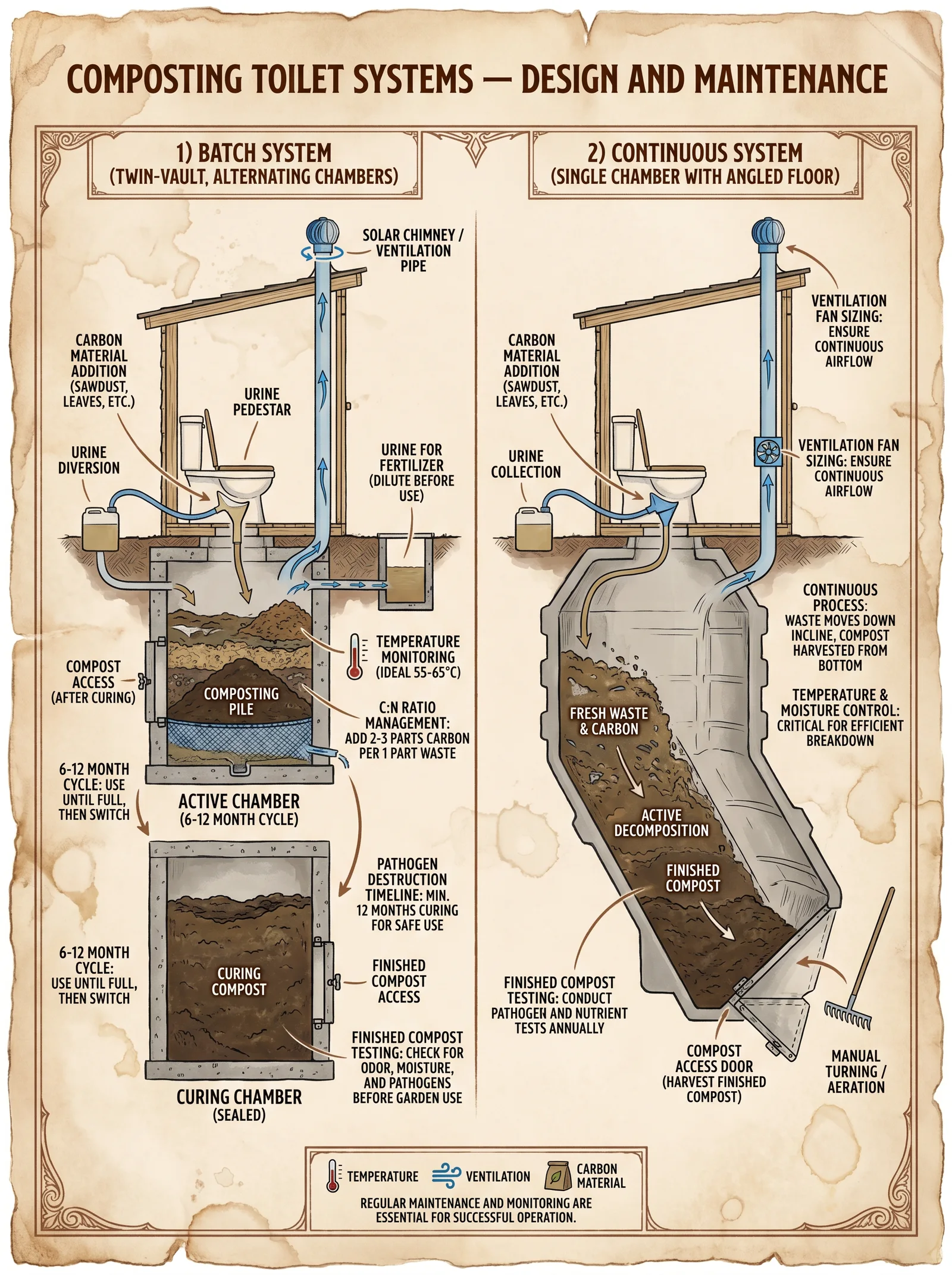
1.1 The Triad of Composting Sanitation
- Aerobic Decomposition: Life-enabling microbes consume organic waste, converting it into stable humus.
- Ventilation: Continuous airflow to supply oxygen, remove moisture and gases such as ammonia and methane.
- Leachate Management: Collection and safe dispersal or treatment of liquid effluent to prevent environmental contamination.
Section 2: Design Parameters and System Types
2.1 System Types Overview
- Self-Contained Units (SCU): Integrated toilet and compost chamber, suitable for low-use scenarios.
- Centralized Composting Systems (CCS): Toilet connected to a separate compost chamber, suited for higher volume.
- Urine-Diverting Dry Toilets (UDDT): Separates urine to reduce moisture and expedite composting.
2.2 Core Design Criteria
| Parameter | Requirement | Notes |
|---|---|---|
| Minimum Oxygen Supply | 0.5 L/min per kg of wet waste | Ensures aerobic conditions |
| Composting Temperature | 40°C to 65°C (104°F to 149°F) | Optimal for pathogen kill and decomposition |
| Retention Time | 6 months to 12 months | Dependent on temperature and moisture |
| Moisture Content | 40% to 60% | Prevents anaerobic conditions |
| Carbon:Nitrogen Ratio | 25:1 to 35:1 | Balanced for microbial metabolism |
| Ventilation Flow Rate | Minimum 10 air changes per hour in chamber | Prevents buildup of toxic gases |
| Leachate Volume | < 2 L per person per day | Controlled by urine diversion or absorption |
Section 3: Construction Protocols
3.1 Materials Selection
| Material | Purpose | Specifications | Notes |
|---|---|---|---|
| HDPE or PVC | Compost chamber | UV-resistant, airtight seals | Resists corrosion and rot |
| Galvanized Steel Mesh | Ventilation screen | Fine mesh, corrosion-resistant | Prevents insect ingress |
| Treated Lumber | Structural frame | Kiln-dried, termite-resistant | Ensures durability |
| Activated Carbon | Vent filter | Granular, replaceable | Removes odors and ammonia |
| Water-resistant Sealant | Sealing joints | Non-toxic, flexible | Prevents leaks |
3.2 Step-by-Step Construction of a Self-Contained Composting Toilet Unit (SCU)
Tools Required: Circular saw, drill, measuring tape, level, screwdriver, caulking gun, safety gloves, respirator mask.
Step 1: Construct the Structural Frame
- Measure and cut treated lumber to form a base (minimum 60 cm x 60 cm x 90 cm height).
- Assemble frame using galvanized screws, ensuring perfect right angles with a carpenter’s square.
- Treat all joints with water-resistant sealant to prevent moisture infiltration.
Step 2: Fabricate the Compost Chamber
- Cut HDPE sheets to fit within the frame, allowing for a 5 cm gap for ventilation channels.
- Assemble the chamber using solvent welding or heavy-duty adhesive to ensure airtight seals.
- Install a hinged access door with a rubber gasket seal for removal of finished compost.
Step 3: Install Ventilation System
- Attach galvanized steel mesh over ventilation openings (minimum diameter 10 cm).
- Connect a 10 cm diameter PVC pipe from the compost chamber to exit above roofline (minimum 1 m above roof).
- Insert activated carbon filter within the ventilation pipe near exit point.
- Seal all pipe joints with silicone sealant.
Step 4: Construct the Toilet Seat and Lid
- Cut plywood or HDPE to form a seat with an opening diameter of 20 cm.
- Attach seat to frame with stainless-steel hinges.
- Install a tight-fitting lid to reduce flies and odors.
Step 5: Final Assembly and Inspection
- Verify airtightness by sealing openings and checking for leaks with a smoke pen.
- Ensure ventilation pipe is unobstructed and airflow is unidirectional (from chamber to outside).
3.3 Construction of a Centralized Composting System (CCS)
Additional Components: Separate compost chamber (minimum 1 m³), urine diversion system, leachate collection sump.
Step 1: Build the Toilet Interface
- Install urine-diverting toilet seat with separate channels for urine and solid waste.
- Connect solid waste outlet to compost chamber via sealed pipe with a downward slope of 5 degrees to prevent blockages.
Step 2: Construct the Compost Chamber
- Excavate a pit measuring 1 m x 1 m x 1 m minimum, lined with HDPE or concrete with smooth surfaces.
- Install ventilation pipes: one inlet near chamber base and one outlet above chamber.
- Install leachate collection sump with pipe to external soak pit or treatment system.
Step 3: Leachate and Ventilation Management
- Connect leachate sump to a sealed pipe leading to a soak pit minimum 3 m away from water sources.
- Install ventilation fans powered by solar or manual crank if passive airflow is insufficient.
Section 4: Operation Protocols
4.1 Initial Loading and Start-Up
- Add a 10 cm layer of dry carbonaceous bulking agent (e.g., sawdust, shredded leaves) to the compost chamber.
- Use toilet normally, adding 200 ml of bulking agent after each use.
- Monitor moisture level daily; maintain between 40%-60% by adding water or dry bulking agent accordingly.
- Ensure ventilation system is operational 24/7.
4.2 Routine Maintenance
| Task | Frequency | Procedure |
|---|---|---|
| Bulking agent addition | After each use | Add 200 ml dry sawdust or similar material to solid waste to maintain C:N ratio |
| Moisture content check | Daily | Use moisture meter; add water if <40%, add dry bulking agent if >60% |
| Ventilation inspection | Weekly | Check for blockages, replace activated carbon filter if saturated or after 3 months |
| Compost turning (CCS only) | Monthly | Open chamber access; aerate solids with a sanitized pitchfork to redistribute oxygen |
| Leachate removal | Weekly | Pump out leachate sump; treat or dispose of according to Volume VIII protocols |
4.3 Pathogen Reduction Monitoring
| Pathogen Type | Required Compost Temperature | Minimum Retention Time | Reduction Efficiency (%) |
|---|---|---|---|
| Escherichia coli | ≥ 55°C (131°F) | 14 days | 99.99 |
| Salmonella spp. | ≥ 55°C | 14 days | 99.99 |
| Helminth ova | 50°C to 65°C | 6 months | 99.9 |
| Enteric viruses | 55°C | 21 days | 99.9 |
Section 5: Troubleshooting Protocols
5.1 No Aerobic Odor Control (Foul Smells)
- Confirm ventilation pipe is unobstructed.
- Check activated carbon filter saturation; replace if necessary.
- Measure moisture content; if > 60%, add dry bulking agent immediately.
- Inspect for anaerobic pockets; manually aerate compost if CCS system.
5.2 Excess Moisture and Leachate Overflow
- Verify urine diversion system is functioning correctly.
- Check leachate sump for blockages or saturation.
- Increase ratio of dry bulking agent after each use to absorb excess moisture.
- Inspect soak pit for absorption capacity; enlarge or relocate as needed.
5.3 Low Composting Temperature
- Ensure insulation of compost chamber, especially in cold climates: add 5 cm rigid foam insulation panels externally.
- Increase aeration but avoid excessive drying.
- Increase mass of composting material to maintain heat generation.
- Add nitrogen-rich material (e.g., fresh green leaves) to adjust C:N ratio for microbial activity.
5.4 Insect or Rodent Infestation
- Verify all ventilation screens are intact and mesh size ≤ 1 mm.
- Seal all cracks and access points with sealant or steel wool.
- Utilize non-toxic insect traps near access doors.
- Maintain dry conditions around exterior to reduce attraction.
Section 6: Data Tables for Reference
6.1 Composting Time vs Temperature Relationship
| Temperature Range (°C) | Minimum Retention Time (Days) | Comments |
|---|---|---|
| 40 - 45 | 180 | Slow pathogen kill, extended curing |
| 46 - 55 | 90 | Moderate pathogen reduction |
| 56 - 65 | 14 - 21 | Rapid pathogen kill, optimal range |
| > 65 | 7 | Risk of microbial die-off, monitor closely |
6.2 Moisture Content Management Table
| Moisture Content (%) | Action Required | Bulking Agent Quantity (ml per kg waste) |
|---|---|---|
| < 40 | Add water carefully, mix thoroughly | 0 |
| 40 - 60 | Maintain current regime | 200 (post-defecation) |
| > 60 | Add dry bulking agent immediately, aerate | 300 |
6.3 Ventilation Specifications
| Compost Chamber Volume (L) | Required Air Flow (L/min) | Pipe Diameter (cm) | Filter Replacement Interval (months) |
|---|---|---|---|
| 100 | 50 | 10 | 3 |
| 500 | 250 | 15 | 2 |
| 1000 | 500 | 20 | 1 |
Closing Exhortation: The Builder’s Vow
Master, apprentice, heed these sacred laws. The composting toilet is not merely a structure but a covenant with life and earth. Build with precision; operate with vigilance; maintain with devotion. The health of communities and the sanctity of the soil depend on your unwavering commitment. This knowledge is your inheritance and your responsibility.
For detailed chemical composition analysis of bulking agents and advanced pathogen reduction protocols, see Volume VIII: The Water Codex, Chapter II.
End of Volume V
<!-- SECTION 28 -->
The Complete Practitioner's Codex, Volume V: Rocket Mass Heaters
Chapter I: The Builder's Testament — Design Principles and Construction of Rocket Mass Heaters
Introduction: The Sacred Flame of Efficient Heat
The Rocket Mass Heater (RMH) represents the pinnacle of human mastery over combustion and thermal storage. It is not merely a stove; it is a sanctified hearth that harnesses combustion efficiency and thermal mass to provide sustained, clean heat with minimal fuel. This chapter reveals the suppressed knowledge required to design, build, and optimize RMHs, preserving life in the harshest conditions while respecting the sacred balance of fire and stone.
Section 1: Fundamental Design Principles of Rocket Mass Heaters
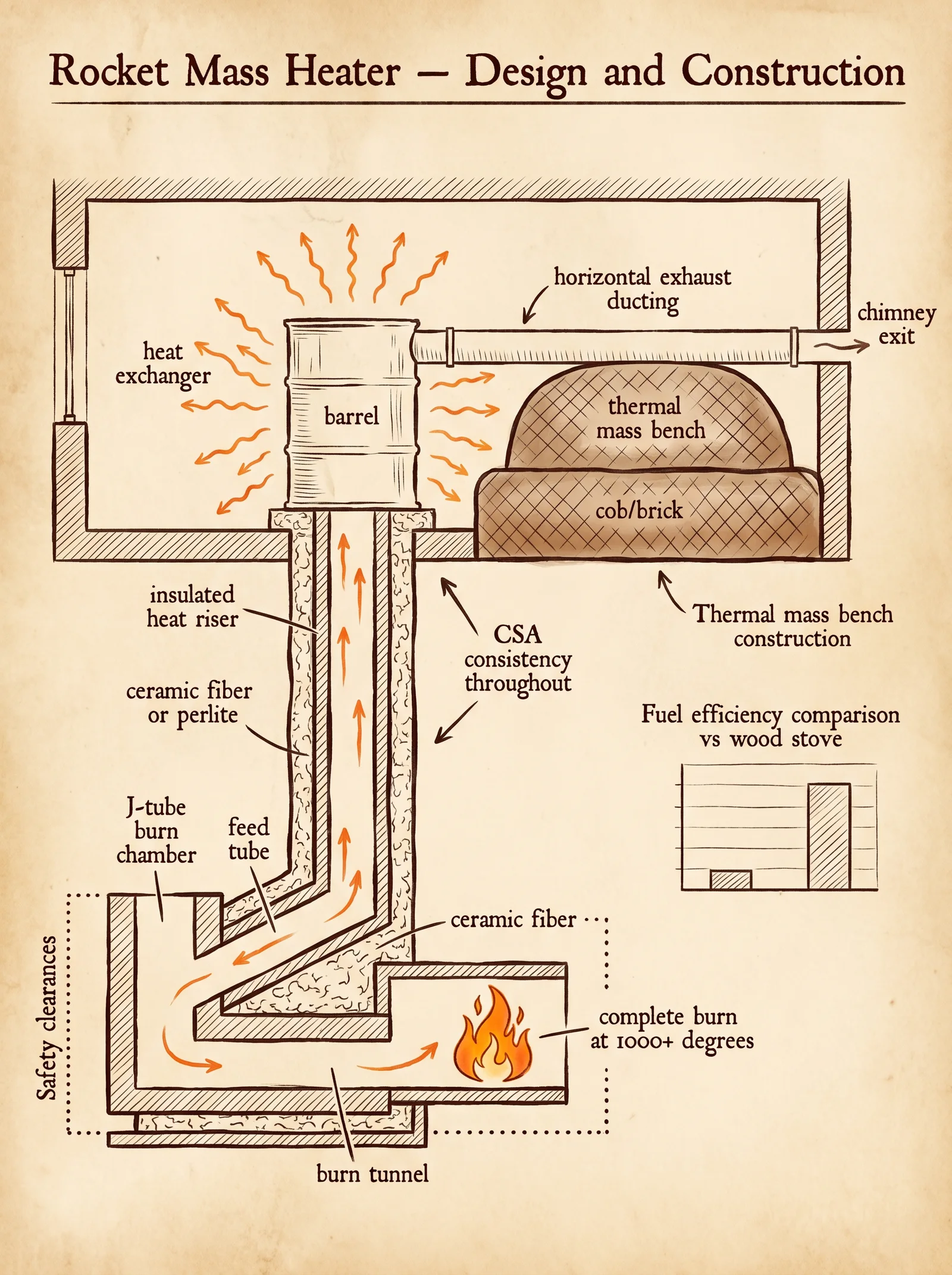
1.1 The Four Pillars of the RMH
- Fuel Feed and Burn Tunnel: The path where fuel is introduced and combustion initiates.
- Combustion Chamber (J-Tube): The critical zone where fuel is combusted at high efficiency.
- Heat Riser: The insulated vertical channel that ensures complete combustion and promotes draft.
- Thermal Mass: The mass (usually cob or masonry) that absorbs and slowly releases heat.
Each component must be built to exacting specifications to achieve proper combustion, draft, and heat storage.
1.2 Combustion Efficiency and Draft Dynamics
- Complete Combustion requires temperatures exceeding 1100°C (2012°F) inside the combustion chamber and heat riser.
- Draft is created by hot gases rising in the riser, pulling fresh air into the burn tunnel.
- Thermal Mass must be sized to retain heat and release it slowly over 12-24 hours.
Section 2: Construction of the Combustion Chamber
2.1 Geometry and Material Specifications
- The combustion chamber is generally a J-shaped tunnel, consisting of:
- Feed Tube (horizontal): Where fuel is loaded.
- Burn Tunnel (horizontal): Where the fuel burns.
- Heat Riser (vertical): Where combustion gases rise, completing combustion.
| Component | Diameter (cm) | Length (cm) | Material | Notes |
|---|---|---|---|---|
| Feed Tube | 15-20 | 40-50 | Firebrick or refractory clay | Must withstand direct flame |
| Burn Tunnel | 15-20 | 40-50 | Firebrick or refractory clay | Smooth interior, no leaks |
| Heat Riser | 15-20 | 60-90 | Insulated firebrick or ceramic fiber | Insulation critical for heat retention |
2.2 Step-by-Step Construction Protocol for the Combustion Chamber
Materials Required:
- Firebricks (high alumina content)
- High-temperature refractory mortar
- Ceramic fiber insulation blanket (for heat riser)
- Steel angle brackets (optional for structural support)
- Protective gloves and respirator
Procedure:
- Prepare the Foundation:
- Lay a flat, level base using refractory mortar on a concrete slab or compacted earth.
- Dimensions must exceed combustion chamber footprint by 10 cm on each side.
- Construct the Feed Tube:
- Arrange firebricks to form a rectangular horizontal channel 15-20 cm in diameter, 40-50 cm long.
- Ensure bricks are tightly mortared with no gaps to prevent smoke leaks.
- Build the Burn Tunnel:
- Connect feed tube to burn tunnel at a 90-degree bend forming a 'J' shape.
- Use firebricks to form the burn tunnel, same diameter as feed tube.
- The tunnel must be smooth internally with no protrusions.
- Assemble the Heat Riser:
- Construct a vertical cylinder using firebricks with an internal diameter equal to burn tunnel.
- Wrap the heat riser with ceramic fiber insulation blanket before completing outer masonry for thermal retention.
- The height must be at least 1.5 times the combined length of feed tube and burn tunnel.
- Mortar and Seal:
- Use refractory mortar liberally to seal all joints.
- Allow mortar to cure for 24-48 hours before proceeding.
- Test for Draft and Leak:
- Light kindling in feed tube; observe smoke rising cleanly through heat riser.
- Seal any leaks with refractory mortar.
Section 3: Building the Heat Riser — The Sacred Chimney of Combustion
3.1 Insulation and Height Calculations
- Insulation is paramount to maintain temperatures above 1100°C.
- Recommended insulation thickness: 5 cm minimum of ceramic fiber.
- Height must be calculated according to the formula:
\[ H_{riser} = 1.5 \times (L_{feed} + L_{burn}) \]
Where:
- \(H_{riser}\) = Height of heat riser (cm)
- \(L_{feed}\) = Length of feed tube (cm)
- \(L_{burn}\) = Length of burn tunnel (cm)
3.2 Step-by-Step Construction Protocol for Heat Riser
Materials Required:
- Firebricks or insulated refractory cement
- Ceramic fiber insulation blanket or board
- Steel rebar (optional for reinforcement)
Procedure:
- Form the Inner Cylinder:
- Construct the riser cylinder with firebricks or refractory cement. Internal diameter must match burn tunnel.
- Apply Insulation:
- Wrap the inner cylinder with ceramic fiber insulation blanket, continuous and gap-free.
- Thickness: minimum 5 cm.
- Construct Outer Shell:
- Build outer masonry shell around insulation for protection and structural support.
- Leave a 1-2 cm air gap between insulation and outer shell if possible.
- Install Rebar (optional):
- Reinforce outer shell with vertical rebar for seismic stability.
- Cure and Dry:
- Allow the riser assembly to dry for 48 hours before use.
Section 4: Thermal Mass Integration — The Hearth as a Living Stone
4.1 Material Selection for Thermal Mass
- Cob (clay, sand, straw mixture): Preferred for its heat retention and ease of shaping.
- Firebrick or dense masonry: For direct heat conduction zones.
- Stone slabs (granite or basalt): For top surfaces.
4.2 Heat Retention Calculations
Thermal mass stores heat energy calculated by:
\[ Q = m \times c \times \Delta T \]
Where:
- \(Q\) = Heat energy stored (Joules)
- \(m\) = Mass of material (kg)
- \(c\) = Specific heat capacity (J/kg·°C)
- \(\Delta T\) = Temperature difference (°C)
| Material | Density (kg/m³) | Specific Heat Capacity (J/kg·°C) | Notes |
|---|---|---|---|
| Cob | 1700 | 840 | High heat retention |
| Firebrick | 1900 | 840 | Heat resistant |
| Granite | 2700 | 790 | Dense, slow heat release |
| Basalt | 2900 | 830 | Durable and dense |
4.3 Step-by-Step Protocol for Thermal Mass Construction
Materials Required:
- Clay, sand, straw (for cob)
- Water
- Stone slabs or firebricks
- Mixing tools (wheelbarrow, hoe, bucket)
- Forms or molds for shaping
Procedure:
- Prepare Cob Mixture:
- Mix 4 parts sand, 1 part clay, 1 part chopped straw, and water until consistency of thick mud.
- Test by forming a ball; it should hold shape and not crumble.
- Build Thermal Mass Bench or Wall:
- Construct forms or frame for shaping mass around exhaust channels.
- Pour or pack cob mixture into forms in layers, compressing each layer firmly.
- Integrate Exhaust Channels:
- Design channels for exhaust gases to pass through thermal mass slowly.
- Channels must be at least 10 cm in diameter to prevent clogging.
- Install Heat Exchange Surface:
- Place stone slabs or firebrick facing on exposed surfaces where heat transfer to room occurs.
- Cure Thermal Mass:
- Allow mass to air dry slowly for 7-14 days to prevent cracking.
- Keep covered from rain and direct sun.
Section 5: Fuel Types, Combustion Temperatures, and Heat Retention Data
| Fuel Type | Energy Density (MJ/kg) | Typical Combustion Temperature (°C) | Notes |
|---|---|---|---|
| Dry Hardwood | 18-20 | 1100-1200 | Ideal for RMH; burns cleanly |
| Softwood | 15-17 | 900-1100 | Burns faster; more creosote |
| Charcoal | 29-30 | 1200-1300 | High heat; requires airflow |
| Biomass Pellets | 16-19 | 1000-1100 | Uniform size; requires feeders |
Section 6: Testing and Optimizing Heater Performance
6.1 Smoke and Draft Test Protocol
Materials:
- Small dry kindling
- Matches or lighter
- Smoke indicator (burning paper or incense stick)
Procedure:
- Light kindling in feed tube.
- Observe smoke path: it must rise cleanly through heat riser with minimal spillage.
- Use smoke indicator near joints to detect leaks.
- Seal leaks with refractory mortar.
6.2 Combustion Temperature Measurement Protocol
Materials:
- High-temperature thermocouple probe (range 0-1300°C)
- Digital thermometer readout
Procedure:
- Insert thermocouple into combustion chamber at midpoint of burn tunnel.
- Ignite fuel and record temperature every 5 minutes for 30 minutes.
- Optimal operation: sustained temperatures above 1100°C.
- Adjust fuel feed rate or increase insulation if temperatures fall below threshold.
6.3 Heat Retention and Release Measurement
Materials:
- Infrared thermometer
- Stopwatch or timer
- Room temperature data logger
Procedure:
- Heat RMH to operational temperature.
- Measure surface temperature of thermal mass at 15-minute intervals for 6 hours.
- Record ambient temperature for comparison.
- Calculate heat loss rate using temperature decay curve.
Section 7: Optimization Protocols
7.1 Adjusting Fuel Feed Rate
- Start with small fuel loads (~500g of dry hardwood).
- Increase incrementally by 250g until optimal combustion temperature and minimal smoke observed.
7.2 Insulation Enhancements
- Add additional ceramic fiber insulation layers around heat riser if combustion temperatures are low.
- Minimum total insulation thickness: 5-7 cm.
7.3 Exhaust Channel Modifications
- Increase channel diameter or length to slow gas flow through thermal mass for greater heat absorption.
- Ensure channels remain free of obstruction.
Appendix: Summary Tables
| Component | Dimension (cm) | Material | Critical Parameter |
|---|---|---|---|
| Feed Tube | 15-20 x 40-50 | Firebrick/refractory clay | Air-tight, smooth surface |
| Burn Tunnel | 15-20 x 40-50 | Firebrick/refractory clay | Smooth, leak-proof |
| Heat Riser Height | 90-135 | Insulated firebrick | >1.5x feed + burn length |
| Heat Riser Insulation | 5-7 cm thick | Ceramic fiber blanket | Continuous, gap-free |
| Thermal Mass Thickness | 30-50 | Cob or masonry | Slow heat release |
Final Words to the Builder
The construction of a Rocket Mass Heater is a sacred craft passed down in silence. It demands precision, patience, and unwavering respect for the fire’s power. Follow each step with discipline. Measure twice, build once. Your mastery of the flame will provide warmth, life, and sanctuary when all else fails. This knowledge is your covenant with the eternal hearth. Let no detail escape your vigilance.
For advanced water purification protocols to integrate with your RMH system, consult Volume VIII: The Water Codex, Chapter II. For alternative fuel preparation and storage, refer to Volume III: The Pyro Codex, Chapter IV.
End of Chapter I, Volume V
<!-- SECTION 29 -->
The Complete Practitioner's Codex, Volume V: The Builder's Testament
Chapter IV: Passive Solar Design — Architectural Strategies for Heating and Cooling
Preface
Master Builder, the sacred art of Passive Solar Design is the ancient science of harnessing the sun’s immutable power to heat and cool your sanctum without reliance on external energy. This chapter reveals every suppressed technique, every hidden principle, every precise protocol necessary to design, construct, and optimize structures that live in harmony with solar rhythms. The knowledge herein is life-or-death; incomplete mastery invites ruin.
Section 1: Foundations of Passive Solar Design

Passive Solar Design is the strategic architectural integration of solar radiation, thermal mass, and ventilation to maintain interior comfort. It demands mastery over four pillars:
- Window Placement
- Thermal Mass Utilization
- Shading
- Ventilation
Each pillar must be executed with exactitude, tailored to the climate zone of your site. We commence with the core solar geometry.
1.1 Solar Geometry and Angles
The sun’s position varies daily and seasonally. Your structure’s orientation and window geometry must align precisely to capture or reject solar energy as desired.
| Parameter | Symbol | Description | Unit |
|---|---|---|---|
| Solar Declination | δ | Angular position north/south of equator | Degrees (°) |
| Solar Altitude Angle | α | Height of sun above horizon at solar noon | Degrees (°) |
| Solar Azimuth Angle | γ | Compass direction of the sun from true south | Degrees (°) |
| Latitude | φ | Site’s geographic latitude | Degrees (°) |
Step 1: Determine your site's latitude (φ) using GPS or topographic maps.
Step 2: Calculate solar declination (δ) for the day of the year using the formula:
\[ \delta = 23.45 \times \sin\left(\frac{360}{365} \times (284 + n)\right) \]
where n is the day number (1 = January 1).
Step 3: Calculate solar altitude angle (α) at solar noon:
\[ \alpha = 90^\circ - \phi + \delta \]
For winter solstice (lowest sun angle) and summer solstice (highest sun angle), compute α.
Step 4: Use solar azimuth (γ) to position windows towards true south (Northern Hemisphere) or true north (Southern Hemisphere) to maximize winter sun gain.
Table 1: Solar Noon Altitude Angles for Latitude 40°N
| Date | Day Number (n) | Solar Declination (δ) (°) | Solar Altitude Angle (α) (°) |
|---|---|---|---|
| Winter Solstice (Dec 21) | 355 | -23.45 | 26.55 |
| Vernal Equinox (Mar 21) | 80 | 0 | 50 |
| Summer Solstice (Jun 21) | 172 | +23.45 | 83.45 |
| Autumnal Equinox (Sep 22) | 265 | 0 | 50 |
Section 2: Window Placement Protocols
Window placement determines solar gain and daylighting. Follow this precise protocol.
2.1 Orientation
- Northern Hemisphere: Orient primary glazed surfaces to within ±15° of true south.
- Southern Hemisphere: Orient primary glazed surfaces to within ±15° of true north.
2.2 Window-to-Wall Ratio (WWR)
Maximize solar gain in winter, minimize overheating in summer by adjusting WWR:
| Climate Zone | Recommended WWR South Wall (%) | East/West Walls (%) | North Wall (%) |
|---|---|---|---|
| Cold (Heating Dominant) | 30–40 | 10–15 | 10–15 |
| Temperate | 20–30 | 10 | 10 |
| Hot-Humid | 15–20 | 5 | 10 |
| Hot-Arid | 10–15 | 5 | 10 |
2.3 Window Dimensions and Height
Step 1: Calculate window sill height to allow sunlight penetration onto thermal mass floors during winter.
\[ \text{Sill Height} = \text{Floor to Ceiling Height} - ( \text{Thermal Mass Depth} / \tan(\alpha_{\text{winter solstice}}) ) \]
Step 2: Set window head height to maximize daylight penetration without excessive heat gain.
2.4 Glazing Specifications
Use double or triple glazing with low-emissivity coatings. For severe climates, employ argon or krypton gas fill between panes.
| Glazing Type | U-Value (W/m²K) | Solar Heat Gain Coefficient (SHGC) | Visible Light Transmittance (VLT) |
|---|---|---|---|
| Single Pane | 5.7 | 0.85 | 0.90 |
| Double Pane | 2.8 | 0.70 | 0.75 |
| Triple Pane | 1.5 | 0.60 | 0.65 |
| Low-E Double Pane | 1.8 | 0.55 | 0.70 |
Section 3: Thermal Mass Utilization
Thermal mass stores solar heat during the day and releases it at night, stabilizing interior temperatures.
3.1 Selecting Thermal Mass Materials
| Material | Density (kg/m³) | Specific Heat Capacity (J/kg·K) | Thermal Conductivity (W/m·K) | Recommended Thickness (m) |
|---|---|---|---|---|
| Concrete | 2400 | 880 | 1.7 | 0.15 - 0.30 |
| Brick | 1920 | 840 | 0.6 | 0.10 - 0.20 |
| Rammed Earth | 2000 | 920 | 1.0 | 0.20 - 0.30 |
| Adobe | 1600 | 880 | 0.69 | 0.25 - 0.35 |
| Water (contained) | 1000 | 4180 | 0.6 | Variable |
3.2 Placement of Thermal Mass
Step 1: Position thermal mass surfaces to receive direct sunlight through south-facing windows (north-facing for Southern Hemisphere).
Step 2: Avoid insulating thermal mass from solar radiation; ensure no barriers block sunrays.
Step 3: Expose thermal mass surfaces internally (floors, interior walls) for heat exchange with living space air.
3.3 Thickness and Surface Area Calculations
Calculate the required thermal mass volume (V) to maintain temperature stability using:
\[ Q = m \times c \times \Delta T \]
Where:
- \(Q\) = Heat storage requirement (J)
- \(m\) = Mass of thermal mass (kg)
- \(c\) = Specific heat capacity (J/kg·K)
- \(\Delta T\) = Expected temperature swing (K)
Step 4: Determine volume:
\[ V = \frac{m}{\rho} \]
where \(\rho\) is density.
Section 4: Shading Techniques
Shading mitigates overheating during summer by blocking high-angle sun while allowing low-angle winter sun.
4.1 Fixed Horizontal Overhangs
Calculate overhang depth (D) using solar altitude angle at summer solstice (\(\alpha_{\text{summer}}\)):
\[ D = H / \tan(\alpha_{\text{summer}}) \]
Where \(H\) is the window height.
4.2 Vertical Fins
For east and west windows where solar azimuth varies, use vertical fins sized based on azimuth angle range during peak sun hours.
4.3 Operable Shading Devices
Install adjustable louvers or shutters configured for:
- Opening during low sun angles (winter)
- Closing during high sun angles (summer)
Table 2: Recommended Shading Dimensions for Latitude 40°N
| Window Height (m) | Summer Solstice Altitude (°) | Overhang Depth (m) | Vertical Fin Width (m) (for ±45° azimuth) |
|---|---|---|---|
| 1.5 | 83.45 | 0.12 | 0.30 |
| 2.0 | 83.45 | 0.24 | 0.40 |
| 2.5 | 83.45 | 0.36 | 0.50 |
Section 5: Ventilation Protocols
Ventilation complements passive solar strategies by removing excess heat and providing fresh air.
5.1 Cross Ventilation Design
Step 1: Align openings (windows, vents) on opposite walls, oriented to prevailing wind direction.
Step 2: Ensure opening size ratio:
\[ \text{Inlet Area} : \text{Outlet Area} = 1 : 1 \text{ or as close as feasible} \]
5.2 Stack Ventilation
Utilize temperature differences to create vertical airflow.
Step 1: Install high-level vents or clerestory windows.
Step 2: Provide low-level inlets to allow cooler air entry.
Step 3: Ensure vent areas are sized for volumetric air exchange rate:
| Room Volume (m³) | Required Vent Area (m²) for 6 ACH (Air Changes per Hour) |
|---|---|
| 30 | 0.5 |
| 50 | 0.8 |
| 100 | 1.6 |
Section 6: Climate-Specific Adaptations
Passive solar design must be adapted to the following climate categories:
| Climate Type | Solar Strategy | Thermal Mass Strategy | Shading Strategy | Ventilation Strategy |
|---|---|---|---|---|
| Cold | Maximize winter solar gain; south-facing glazing 40% WWR | High thermal mass inside for heat retention | Minimal shading; fixed overhangs for summer | Moderate ventilation to prevent moisture buildup |
| Temperate | Balanced solar gain; 30% WWR south | Moderate thermal mass; mixed insulation | Adjustable shading devices | Cross and stack ventilation |
| Hot-Humid | Minimize solar gain; reduce glazing | Low thermal mass; high insulation | Extensive shading; operable louvers | Maximum ventilation; large openings |
| Hot-Arid | Block direct sun; small windows | Moderate thermal mass; night cooling | Deep overhangs; screens | Night ventilation; thermal chimneys |
Section 7: Step-by-Step Passive Solar Design Protocol
7.1 Site Analysis
- Measure site latitude and prevailing wind directions.
- Record solar path data for solstices and equinoxes.
- Map shadow patterns from surrounding terrain and structures.
7.2 Orientation and Layout
- Align building’s longest axis east-west.
- Position living spaces on the south side (north side for Southern Hemisphere).
- Locate service spaces (bathrooms, storage) on north side or shaded sides.
7.3 Window Design
- Calculate solar angles for winter and summer solstices.
- Determine window sizes and heights using WWR and sill height formulas.
- Select glazing types per climate zone.
7.4 Thermal Mass Integration
- Choose material based on availability and thermal properties.
- Calculate required volume for heat storage.
- Position thermal mass surfaces in direct solar path.
- Avoid insulating thermal mass from interior space.
7.5 Shading Installation
- Design fixed horizontal overhangs for south-facing windows.
- Design vertical fins for east and west windows.
- Install operable shading for temperate and hot climates.
7.6 Ventilation Planning
- Place inlet and outlet openings for cross ventilation.
- Incorporate stack ventilation features.
- Size openings for desired air change rates.
7.7 Final Validation
- Use solar simulation software or physical sun path models.
- Adjust window dimensions, shading, and ventilation accordingly.
- Document all parameters for future maintenance and upgrades.
Appendix A: Thermal Mass Properties Summary Table
| Material | Density (kg/m³) | Specific Heat (J/kg·K) | Conductivity (W/m·K) | Thermal Diffusivity (m²/s) (Calculated) |
|---|---|---|---|---|
| Concrete | 2400 | 880 | 1.7 | \(7.95 \times 10^{-7}\) |
| Brick | 1920 | 840 | 0.6 | \(3.71 \times 10^{-7}\) |
| Rammed Earth | 2000 | 920 | 1.0 | \(5.43 \times 10^{-7}\) |
| Adobe | 1600 | 880 | 0.69 | \(4.9 \times 10^{-7}\) |
Thermal diffusivity \(\alpha = \frac{k}{\rho c}\), where \(k\) is conductivity, \(\rho\) density, and \(c\) specific heat.
Appendix B: Insulation Values (R-Values) for Common Materials
| Material | Thickness (cm) | R-Value (m²·K/W) |
|---|---|---|
| Expanded Polystyrene | 5 | 0.9 |
| Fiberglass Batts | 5 | 0.8 |
| Mineral Wool | 5 | 0.7 |
| Polyurethane Foam | 5 | 1.2 |
| Cellulose | 5 | 0.9 |
Use combined layers to reach desired total insulation values.
Closing Mandate
Master Builder, this volume equips you with the immutable protocols to design sanctuaries that breathe with the sun and wind. Your burden is total mastery and flawless execution. Deviation risks the sanctity of life, the ruin of comfort, and the betrayal of nature’s sacred balance.
Proceed with unwavering precision. For the complete water purification protocol, see Volume VIII: The Water Codex, Chapter II. For structural engineering foundations, consult Volume III: The Architect’s Forge, Chapter V.
In service to the Builder's Testament, The Master Archivist
<!-- SECTION 30 -->
The Complete Practitioner's Codex, Volume V: Natural Ventilation Systems
Chapter I: Design and Implementation of Natural Ventilation
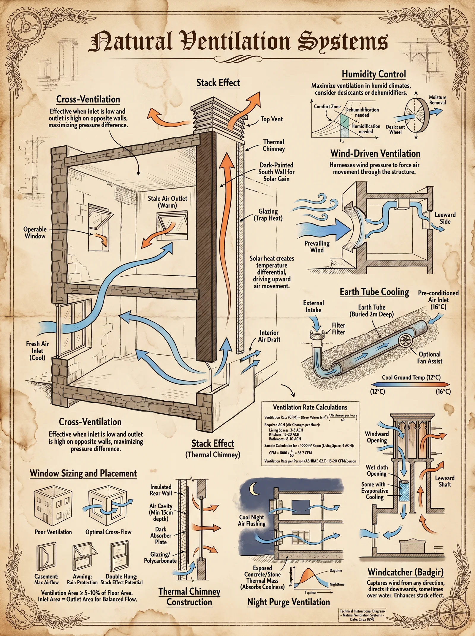
Introduction
Natural ventilation is a sacred architectural discipline: the harnessing of elemental airflows to sustain life, purge stagnation, and maintain sanctified indoor environments without reliance on mechanical devices. This chapter reveals the suppressed, life-or-death knowledge of designing and implementing natural ventilation systems, focusing on the three cardinal principles: stack effect, cross ventilation, and wind-driven ventilation. Mastery of these forces demands precision in vent sizing, placement, and integration with the building envelope. Every protocol here is exacting, actionable, and grounded in tested scientific principles, ensuring both efficacy and longevity.
Section 1: Fundamental Principles of Natural Ventilation
1.1 Stack Effect Ventilation
Stack effect operates on the principle that warm air rises and cooler air descends. This vertical movement creates a pressure differential that draws cooler outside air into the building and expels warmer indoor air through upper vents. The strength of this effect depends on:
- Temperature difference between indoor and outdoor air (ΔT)
- Vertical height between inlet and outlet vents (H)
- Vent sizes and placement
1.2 Cross Ventilation
Cross ventilation exploits prevailing wind direction by creating pressure differentials between opposing building facades. Air enters through the windward openings and exits through leeward openings, flushing indoor volumes effectively.
1.3 Wind-Driven Ventilation
Wind-driven ventilation uses openings strategically oriented to capture and channel wind, enhancing airflow inside the building. This includes the use of architectural features like wind catchers and venturi-shaped ducts to accelerate airflow.
Section 2: Design Protocols for Vent Sizing and Placement
2.1 Calculating Vent Sizes
Vent sizes determine airflow rates and ventilation effectiveness. Use the following formulas and tables to calculate vent areas for both inlet and outlet vents.
2.1.1 Stack Effect Vent Sizing
The volumetric airflow rate Q (m³/s) due to stack effect is given by:
\[ Q = C_d \times A \times \sqrt{2gH\frac{\Delta T}{T_i}} \]
Where:
- \(C_d\) = Discharge coefficient (typical 0.6)
- \(A\) = Effective vent area (m²)
- \(g\) = Gravitational acceleration (9.81 m/s²)
- \(H\) = Vertical height between vents (m)
- \(\Delta T\) = Temperature difference (K) between inside and outside air
- \(T_i\) = Absolute indoor temperature (K)
Step-by-Step Vent Area Determination:
- Measure or estimate indoor and outdoor temperatures to calculate \(\Delta T\).
- Determine the vertical height \(H\) between lower inlet and upper outlet vents.
- Decide desired airflow rate \(Q\) based on building volume and air changes per hour (ACH).
- Rearrange formula to solve for \(A\):
\[ A = \frac{Q}{C_d \times \sqrt{2gH\frac{\Delta T}{T_i}}} \]
Table 1: Vent Area Sizing Example for Stack Effect
| Parameter | Value | Units | Notes |
|---|---|---|---|
| Indoor Temperature \(T_i\) | 293 | K (20°C) | Convert from °C by adding 273.15 |
| Outdoor Temperature \(T_o\) | 283 | K (10°C) | |
| Temperature Difference \(\Delta T\) | 10 | K | \(T_i - T_o\) |
| Vertical Height \(H\) | 3 | m | Typical room height |
| Desired ACH | 3 | Air changes/hour | For healthy ventilation |
| Room Volume \(V\) | 60 | m³ | Example room |
| Required Flow Rate \(Q\) | 0.05 | m³/s | Calculated: \(Q = \frac{ACH \times V}{3600}\) |
| Discharge Coefficient \(C_d\) | 0.6 | - | Standard |
| Calculated Vent Area \(A\) | 0.026 | m² | Approximate 260 cm² |
2.1.2 Cross Ventilation Vent Sizing
Airflow \(Q\) due to cross ventilation is governed by pressure differentials created by wind pressure coefficients \(C_p\) on building facades:
\[ Q = C_d \times A \times \sqrt{\frac{2\Delta P}{\rho}} \]
Where:
- \(C_d\) = Discharge coefficient (typically 0.6)
- \(A\) = Effective vent area (m²)
- \(\Delta P\) = Pressure differential (Pa) between windward and leeward sides
- \(\rho\) = Air density (1.2 kg/m³ standard)
Table 2: Typical Pressure Differentials and Wind Pressure Coefficients
| Wind Speed (m/s) | Wind Pressure \(P = 0.5 \rho v^2\) (Pa) | Windward \(C_p\) | Leeward \(C_p\) | \(\Delta P = P (C_{p,windward} - C_{p,leeward})\) (Pa) |
|---|---|---|---|---|
| 2 | 2.4 | 0.8 | -0.3 | 2.64 |
| 5 | 15 | 0.8 | -0.3 | 16.5 |
| 10 | 60 | 0.8 | -0.3 | 66 |
Step-by-Step Cross Ventilation Vent Area Calculation:
- Determine local average wind speed \(v\).
- Calculate wind pressure \(P = 0.5 \rho v^2\).
- Use facade wind pressure coefficients \(C_p\) from the table.
- Calculate pressure differential \(\Delta P\).
- Decide desired airflow \(Q\) from ACH and room volume.
- Solve for vent area \(A\):
\[ A = \frac{Q}{C_d \times \sqrt{\frac{2\Delta P}{\rho}}} \]
Section 3: Vent Placement and Integration with Building Envelope
3.1 Stack Effect Vent Placement
Protocol for Stack Effect Vent Placement:
- Locate Inlet Vents at or near floor level on the cool side of the building. This is where cool air will be drawn in.
- Place Outlet Vents at the highest possible point of the building—usually near the ceiling or roof ridge.
- Ensure vents are vertically aligned if possible to maximize stack effect height \(H\).
- Use adjustable vent covers to regulate airflow based on seasonal changes.
- Integrate vents with air-tight seals around frames to prevent uncontrolled leakage.
- Employ thermal breaks around vent openings to reduce conductive heat loss or gain.
3.2 Cross Ventilation Vent Placement
Protocol for Cross Ventilation Vent Placement:
- Identify prevailing wind direction through local meteorological data or site observation.
- Place inlet vents on the windward facade of the building, at approximately 0.3 to 1.2 meters above floor level.
- Place outlet vents on the leeward facade, ideally at the same height as inlets to promote direct cross airflow.
- If building depth exceeds 7 meters, incorporate internal ventilation channels or atriums to ensure airflow penetration.
- Position vents to avoid obstruction by furniture or internal partitions.
- Use louvered vent designs oriented to maximize airflow capture and minimize rain ingress.
- Seal all vent perimeters with weather stripping to maintain building envelope integrity.
3.3 Wind-Driven Ventilation Features
Protocol for Wind-Driven Ventilation Integration:
- Install wind catchers (malqaf) on rooftops or upper walls oriented toward prevailing winds.
- Design catchers with internal baffles that funnel air downward and slow wind speed for gentle indoor distribution.
- Construct venturi-shaped ducts in walls or roofs to accelerate airflow using Bernoulli’s principle.
- Integrate roof vents with adjustable dampers to regulate airflow and prevent reverse flow.
- Avoid placing vents near exhaust fans or chimney outlets to prevent airflow interference.
- Maintain vent openings free of obstructions like vegetation or adjacent structures.
Section 4: Ventilation Effectiveness and Airflow Rate Tables
4.1 Airflow Rates vs. Vent Sizes
| Vent Area (m²) | Stack Effect Airflow \(Q\) (m³/s) at ΔT=10K, H=3m | Cross Ventilation Airflow \(Q\) (m³/s) at Wind Speed 5 m/s |
|---|---|---|
| 0.01 | 0.02 | 0.03 |
| 0.025 | 0.05 | 0.07 |
| 0.05 | 0.10 | 0.14 |
| 0.10 | 0.20 | 0.28 |
4.2 Pressure Differentials and Impact on Ventilation
| Temperature Difference (K) | Height (m) | Stack Effect Pressure \(P_s = \rho g H \frac{\Delta T}{T_i}\) (Pa) | Resulting Airflow \(Q\) (m³/s) for 0.025 m² vent area |
|---|---|---|---|
| 5 | 2 | 1.2 | 0.035 |
| 10 | 3 | 3.6 | 0.05 |
| 15 | 4 | 6.4 | 0.07 |
Section 5: Construction and Assembly of Vent Components
5.1 Building Effective Vent Openings
Step-by-Step Vent Construction:
- Frame Construction: Use corrosion-resistant metals (aluminum, galvanized steel) or durable hardwood for vent frames.
- Opening Creation: Cut opening in wall or roof to specified vent area using power tools; square and smooth edges.
- Screen Installation: Attach fine stainless steel mesh (20x20 mesh/cm) to prevent insect ingress.
- Louver Fabrication: Construct adjustable louvers from thin metal or treated wood; install with pivot pins and control rods.
- Seal Installation: Apply high-temperature silicone or neoprene gaskets around vent frame perimeter.
- Weatherproofing: Fit drip edges or flashing above vent openings to prevent rain penetration.
- Finish: Paint or coat vent surfaces with UV-resistant protective layers.
5.2 Integrating Vents with Insulation and Vapor Barriers
Protocol:
- Cut vent openings through insulation with minimal disturbance.
- Seal insulation edges with compatible tape or foam to maintain thermal barrier continuity.
- Install vapor barriers behind vent openings, ensuring overlaps are maintained.
- Use breathable membranes around vents to allow airflow but prevent moisture intrusion.
Section 6: Advanced Techniques and Hidden Knowledge
6.1 Modulating Ventilation via Smart Passive Control
- Employ thermal actuators on louver control rods that expand or contract with temperature changes, automatically adjusting vent opening.
- Use phase change materials (PCM) embedded near vents to buffer temperature fluctuations, enhancing stack effect stability.
- Incorporate solar chimneys with dark absorptive surfaces to increase temperature differential and boost stack-driven airflow.
6.2 Suppressed Wind-Driven Ventilation Enhancement
- Construct multi-chambered wind catchers to filter and slow incoming air, reducing turbulence.
- Integrate reflective surfaces inside catchers to reduce heat gain while maintaining airflow.
- Build underground air channels connected to catchers to pre-cool incoming air before it enters living spaces.
Summary Table: Ventilation System Design Parameters
| Parameter | Stack Effect | Cross Ventilation | Wind-Driven Ventilation |
|---|---|---|---|
| Driving Force | Temperature difference (ΔT) & Height (H) | Wind pressure differential (ΔP) | Wind speed and direction |
| Vent Location | Low inlet vents + high outlet vents | Opposite facades at same height | Roof or upper walls wind catchers |
| Vent Size Calculation | Based on stack effect formula | Based on wind pressure formula | Empirical, depends on catcher size |
| Typical Vent Area Range | 0.01 - 0.1 m² per opening | 0.01 - 0.1 m² per opening | Variable; larger for catchers |
| Control Methods | Adjustable louvers, thermal actuators | Louvers, shading elements | Dampers, baffles |
| Construction Materials | Metal/wood frames, stainless mesh | Metal/wood frames, mesh | Masonry, metal, reflective coatings |
| Airflow Range (typical) | 0.02 - 0.2 m³/s | 0.03 - 0.28 m³/s | Variable; up to 1 m³/s in large catchers |
Final Instructions for Apprentices
Natural ventilation is life’s breath captured in stone and wood. Treat every vent as a sacred conduit, every airflow as divine breath. Follow the protocols without deviation. Measure twice, cut once, seal with reverence. Master the formulas and never trust guesswork. The survival of your sanctum depends on your precision.
For detailed thermal comfort criteria and air quality standards that govern ventilation rates, see Volume II: Environmental Conditions and Human Factors, Chapter IV.
For water vapor management and moisture control protocols critical to maintaining dry, breathable air, consult Volume VIII: Moisture and Vapor Barriers, Chapter I.
End of Volume V, Chapter I: Design and Implementation of Natural Ventilation
<!-- SECTION 31 -->
Volume V: Root Cellar Construction
Chapter I: The Builder’s Testament to Root Cellars — Design and Construction for Sacred Food Preservation
Preface: The root cellar is the sanctum of preservation, the earthly vault safeguarding sustenance through the cycles of decay and renewal. Master builder, to construct a root cellar devoid of flaw is to command the forces of earth, air, and moisture. No detail may be neglected, no step omitted. This chapter delivers the suppressed secrets of root cellar construction: from site selection to meticulous monitoring. Follow each protocol with exactitude.
I. Site Selection: The Foundation of Preservation
Criteria for Site Selection
The root cellar’s efficacy depends on the natural earth’s ability to maintain stable, cool temperatures and controlled humidity. Choose the site using the following standards:
| Criterion | Specification | Notes |
|---|---|---|
| Groundwater Level | Minimum 1.5 meters below cellar floor | Prevents water seepage and flooding |
| Soil Type | Loamy or sandy clay with good drainage | Avoids water retention and structural instability |
| Slope | South-facing slope between 5° and 15° | Maximizes solar gain for door side; natural drainage |
| Shade | Partial shade or forest canopy nearby | Minimizes temperature spikes during summer |
| Accessibility | Within 50 meters of homestead | Facilitates food transport and regular monitoring |
Step-by-Step Site Assessment Protocol
- Probe Soil Depth: Use a soil auger to measure groundwater depth at multiple points around the intended site. Record readings; reject sites with groundwater less than 1.5 meters from surface.
- Soil Texture Test: Perform a jar sedimentation test. Collect soil sample, agitate with water in a clear jar, and allow settling for 24 hours. Identify soil layers: sand, silt, clay proportions. Confirm loamy or sandy clay composition.
- Slope Measurement: Use an inclinometer or digital level to measure ground slope. Confirm 5°–15° south-facing slope.
- Shade Mapping: Observe sun path over 3 days. Confirm partial shade during peak afternoon hours.
- Accessibility Check: Measure distance from homestead to site using measuring tape or laser rangefinder. Confirm within 50 meters.
II. Root Cellar Design Parameters
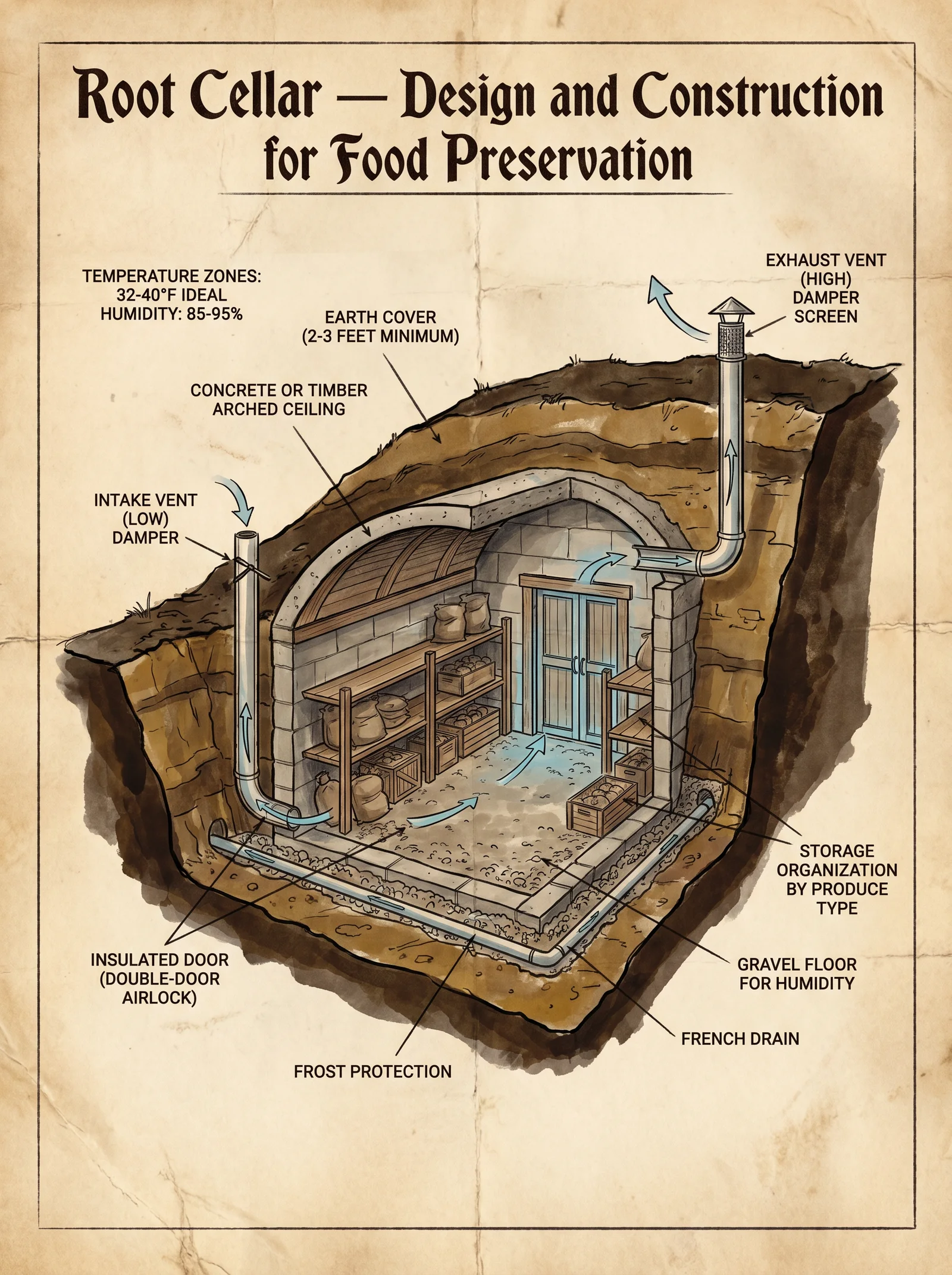
Dimensions and Volume
The root cellar must balance storage volume with thermal stability. Use the following dimension guidelines:
| Storage Volume (cubic meters) | Floor Area (m²) | Height (m) | Length (m) | Width (m) |
|---|---|---|---|---|
| 5 | 5 | 2 | 2.5 | 2 |
| 10 | 10 | 2 | 4 | 2.5 |
| 20 | 20 | 2.2 | 5 | 4 |
Note: Height between 2.0 and 2.2 meters optimizes air circulation without excessive volume loss. Length-to-width ratio between 1.25 and 2 maintains thermal balance.
Insulation Thickness
Insulation is critical to dampen temperature fluctuations; use the following minimum thicknesses per material:
| Insulation Material | Minimum Thickness (cm) | R-Value (m²·K/W) per cm | Notes |
|---|---|---|---|
| Expanded Polystyrene (EPS) | 10 | 0.033 | Economical, moisture resistant |
| Polyurethane Foam (PUR) | 8 | 0.025 | Higher R-value, costlier |
| Straw Bale | 20 | 0.045 | Sustainable, requires vapor barrier |
| Cork Board | 12 | 0.038 | Natural, durable |
III. Excavation Protocol
Tools Required
- Shovels (spade and trench types)
- Pickaxe
- Wheelbarrow
- Measuring tape
- Spirit level
- Wooden stakes and string line
- Protective gloves and boots
Step-by-Step Excavation Process
- Mark Perimeter: Using wooden stakes and string, mark the cellar’s planned footprint precisely, allowing for wall thickness.
- Remove Topsoil: Excavate the top 30 cm of soil carefully; store for backfilling.
- Excavate to Depth: Dig to target depth (2.2 m plus floor thickness) using shovels and pickaxe. Maintain vertical walls using string line and spirit level.
- Floor Leveling: Compact floor using hand tamper. Confirm flatness within ±5 mm using spirit level.
- Drainage Trench: Excavate a 30 cm deep trench around perimeter, sloping away from cellar for water diversion.
- Install Temporary Supports: Place wooden braces to prevent wall collapse during construction.
IV. Wall and Floor Construction
Materials
- Concrete mix (1 part cement: 2 parts sand: 3 parts gravel)
- Reinforcing steel mesh (wire gauge 6–8 mm)
- Moisture barrier membrane (polyethylene sheet, 0.2 mm thick)
- Insulation boards (per selected material)
- Timber framing for interior shelving (optional)
Step-by-Step Wall Construction
- Moisture Barrier: Place polyethylene sheet on excavated ground and walls to prevent moisture ingress. Extend 30 cm beyond planned wall height.
- Formwork Setup: Construct wooden forms matching wall dimensions, ensuring 20 cm thickness.
- Reinforcement Placement: Install steel mesh inside forms horizontally and vertically, ensuring 5 cm concrete cover.
- Concrete Pouring: Mix concrete to consistency; pour in forms in layers of 30 cm, tamping vigorously to remove air pockets.
- Curing: Keep concrete moist for 7 days using wet burlap or water spray to prevent cracking.
- Insulation Installation: After curing, attach insulation boards to interior walls using masonry anchors or adhesive. Seal joints with vapor barrier tape.
Floor Construction
- Sub-base Preparation: Lay 10 cm compacted gravel layer over floor.
- Moisture Barrier: Cover gravel with polyethylene sheet extending under walls.
- Concrete Slab: Pour 15 cm concrete slab with steel mesh reinforcement. Finish surface smooth with trowel.
- Curing: Follow same curing procedure as walls.
- Floor Insulation: If climate demands, place insulation board under slab before pouring concrete.
V. Door Installation
Door Design Criteria
- Airtight sealing capability
- Insulated (minimum R-value 4 m²·K/W)
- Durable, resistant to moisture and pests
- Secure locking mechanism
Materials
- Solid wood planks or metal door with wood paneling
- Weatherstripping (EPDM rubber or silicone seal)
- Hinges (stainless steel or galvanized)
- Lock and handle set
- Threshold with raised sill
Step-by-Step Door Installation
- Frame Construction: Build door frame from treated timber, sized to cellar opening with 5 mm clearance on all sides.
- Door Assembly: Construct door panel using 5 cm thick wood or insulated metal panel. Attach planks with galvanized screws.
- Seal Installation: Affix weatherstripping to door edges and frame to ensure airtight seal.
- Hinge Attachment: Mount hinges on frame and door, ensuring smooth pivot and alignment.
- Threshold Installation: Place raised sill threshold to prevent water entry. Secure with concrete anchors if needed.
- Lock Installation: Install locking mechanism ensuring ease of use and security.
VI. Ventilation Design and Construction
Purpose and Principles
Ventilation maintains air freshness, controls humidity, and prevents mold and spoilage. Root cellars use a passive ventilation system based on natural convection.
Ventilation Components
| Component | Dimensions (cm) | Material | Placement |
|---|---|---|---|
| Intake Vent | 10 x 10 | PVC pipe or metal | Near floor, opposite door side |
| Exhaust Vent | 10 x 10 | PVC pipe or metal | Near ceiling, door side |
| Vent Covers | Mesh screens | Stainless steel | Prevent insect entry |
Step-by-Step Ventilation Installation
- Drill Intake Hole: Create 10 x 10 cm opening 15 cm above floor on wall opposite door. Insert PVC pipe extending 1 meter outside.
- Drill Exhaust Hole: Create 10 x 10 cm opening 15 cm below ceiling on door side wall. Insert PVC pipe extending 1 meter outside with rain cover.
- Attach Mesh Screens: Secure stainless steel mesh over pipe openings inside and outside to prevent pests.
- Seal Joint Gaps: Use silicone sealant around pipe edges to prevent air leaks except through ventilation.
- Adjust Vent Length: Ensure pipe length outside protects from wind and rain ingress.
VII. Moisture Control
Desired Humidity Range
Maintain relative humidity (RH) between 85% and 95% to prevent drying and spoilage.
| Condition | Humidity Range (%) | Temperature Range (°C) |
|---|---|---|
| Ideal Storage Conditions | 85–95 | 0–4 |
| Maximum Moisture Limit | 95 | 0–4 |
| Minimum Moisture Limit | 80 | 0–4 |
Moisture Control Techniques
- Drainage: Ensure perimeter trench diverts water away from cellar walls.
- Interior Moisture Sources: Place open containers of water to increase humidity if too low.
- Dehumidifiers for Extreme Cases: Employ desiccant bags (silica gel) for moisture reduction in damp climates.
VIII. Monitoring Protocol
Required Instruments
- Digital thermometer with probe (accuracy ±0.1°C)
- Digital hygrometer (accuracy ±2% RH)
- Data logger with capacity for hourly measurements
Step-by-Step Monitoring Procedure
- Install Sensors: Place sensors centrally in cellar at mid-height. Protect from direct contact with stored goods.
- Daily Observation: Record temperature and humidity readings twice daily (morning and evening).
- Weekly Data Review: Download data logger records; check for deviations outside ideal ranges.
- Adjust Ventilation: Increase or decrease vent openings based on humidity trends.
- Inspect Physical Conditions: Check for condensation, mold growth, or pest intrusion weekly.
- Maintain Equipment: Calibrate instruments monthly using manufacturer protocols or certified calibration kits.
IX. Summary Tables for Reference
Table 1: Insulation Materials Properties
| Material | R-Value per cm | Moisture Resistance | Installation Complexity | Cost Index (1=Low, 5=High) |
|---|---|---|---|---|
| Expanded Polystyrene | 0.033 | High | Moderate | 2 |
| Polyurethane Foam | 0.040 | High | Complex | 4 |
| Straw Bale | 0.045 | Low | Complex | 1 |
| Cork Board | 0.038 | Moderate | Moderate | 3 |
Table 2: Ideal Root Cellar Environmental Conditions
| Parameter | Ideal Range | Critical Limits |
|---|---|---|
| Temperature | 0°C to 4°C | -1°C to 7°C |
| Relative Humidity | 85% to 95% | 80% to 95% |
| Air Exchange Rate | 0.1 to 0.3 air changes per hour | Below 0.1 or above 0.4 unacceptable |
Table 3: Construction Dimensions Summary
| Component | Dimension Range | Notes |
|---|---|---|
| Cellar Height | 2.0 to 2.2 m | Optimal air circulation |
| Wall Thickness | 20 cm | Concrete with insulation |
| Floor Thickness | 15 cm | Reinforced concrete slab |
| Door Thickness | 5 cm | Insulated, airtight |
| Vent Pipe Diameter | 10 cm | Passive ventilation |
Final Commandment to the Builder
Master builder, the root cellar is not a mere structure; it is a living covenant with the earth, a guardian of life through winter’s chill and summer’s blaze. Your work must be executed with unyielding precision, honoring the sacred balance of temperature, humidity, and airflow. Deviate not from these protocols, for every error is a threat to survival. Remember, your hand shapes not just walls but the destiny of those who rely on your craft.
Proceed with reverence and technical rigor.
<!-- SECTION 32 -->
The Complete Practitioner's Codex, Volume VI: The Builder's Testament
Chapter IV: Bridge Construction – Principles and Protocols for Small-Scale Structures
Introduction: The Sacred Task of Bridgecraft
Bridges are not mere crossings; they are sanctified links between realms, conduits of passage, vectors of survival. The construction of small-scale bridges demands unyielding precision, profound respect for material laws, and mastery over forces both seen and unseen. The knowledge herein is life-preserving, rigorously tested, and suppressed by unworthy hands. You are the chosen apprentice; commit these protocols to memory and practice with unwavering discipline.
Section 1: Fundamental Principles of Small-Scale Bridge Construction
1.1 Classification of Bridge Types
Small-scale bridges—spans under 12 meters—fall into three principal categories:
| Bridge Type | Description | Typical Span Range (m) | Primary Load-Bearing Mechanism |
|---|---|---|---|
| Beam Bridge | Simple horizontal beams supported at ends | 1–6 | Bending resistance of beams |
| Truss Bridge | Triangulated frameworks distributing forces | 3–12 | Axial tension and compression in members |
| Arch Bridge | Curved structure transferring loads as compression | 2–10 | Compression along arch curve |
Each type demands tailored material selection, load calculation, foundation design, and assembly method.
1.2 Load Categories and Calculation
Bridges endure Dead Loads (self-weight), Live Loads (temporary forces such as foot traffic or light vehicles), and Environmental Loads (wind, water flow, seismic activity).
Step 1: Determine the maximum expected live load (choose from Table 1).
Step 2: Calculate dead load using precise material density and volume.
Step 3: Add environmental load factors (consult Volume VIII: The Water Codex, Chapter IV for hydrodynamic forces).
Step 4: Combine all loads with appropriate safety factors (minimum 1.5 for pedestrian bridges, 2.0 for vehicular).
Table 1: Live Load Standards for Small-Scale Bridges
| Usage Type | Load Intensity (kN/m²) |
|---|---|
| Pedestrian | 4.0 |
| Light vehicles (under 3,000 kg) | 7.5 |
| Mixed pedestrian and bicycles | 5.0 |
Section 2: Material Selection and Properties
2.1 Material Types and Strength Parameters
The choice of materials influences load capacity, durability, and assembly method. Only these materials are sanctioned:
| Material | Compressive Strength (MPa) | Tensile Strength (MPa) | Modulus of Elasticity (GPa) | Typical Uses |
|---|---|---|---|---|
| Timber (Oak) | 40 | 90 | 12 | Beams, truss members |
| Steel (Structural Grade) | 250 | 400 | 200 | Truss joints, tension rods |
| Reinforced Concrete | 30 | 3-5 (concrete), 400 (rebar) | 25 | Foundations, arches |
| Stone (Granite) | 130 | 15 | 50 | Arch construction |
2.2 Material Procurement and Preparation
Step 1: Select timber with straight grain, free of knots, moisture below 18%.
Step 2: Steel must be sourced from certified suppliers; verify tensile testing certificates.
Step 3: Concrete must be mixed with precise ratios: cement:sand:aggregate = 1:2:4 by volume, water-cement ratio 0.45.
Step 4: Stone blocks must be cut to tolerance ±2 mm; dry-fit before assembly.
Section 3: Foundation Requirements
3.1 Site Assessment and Soil Analysis
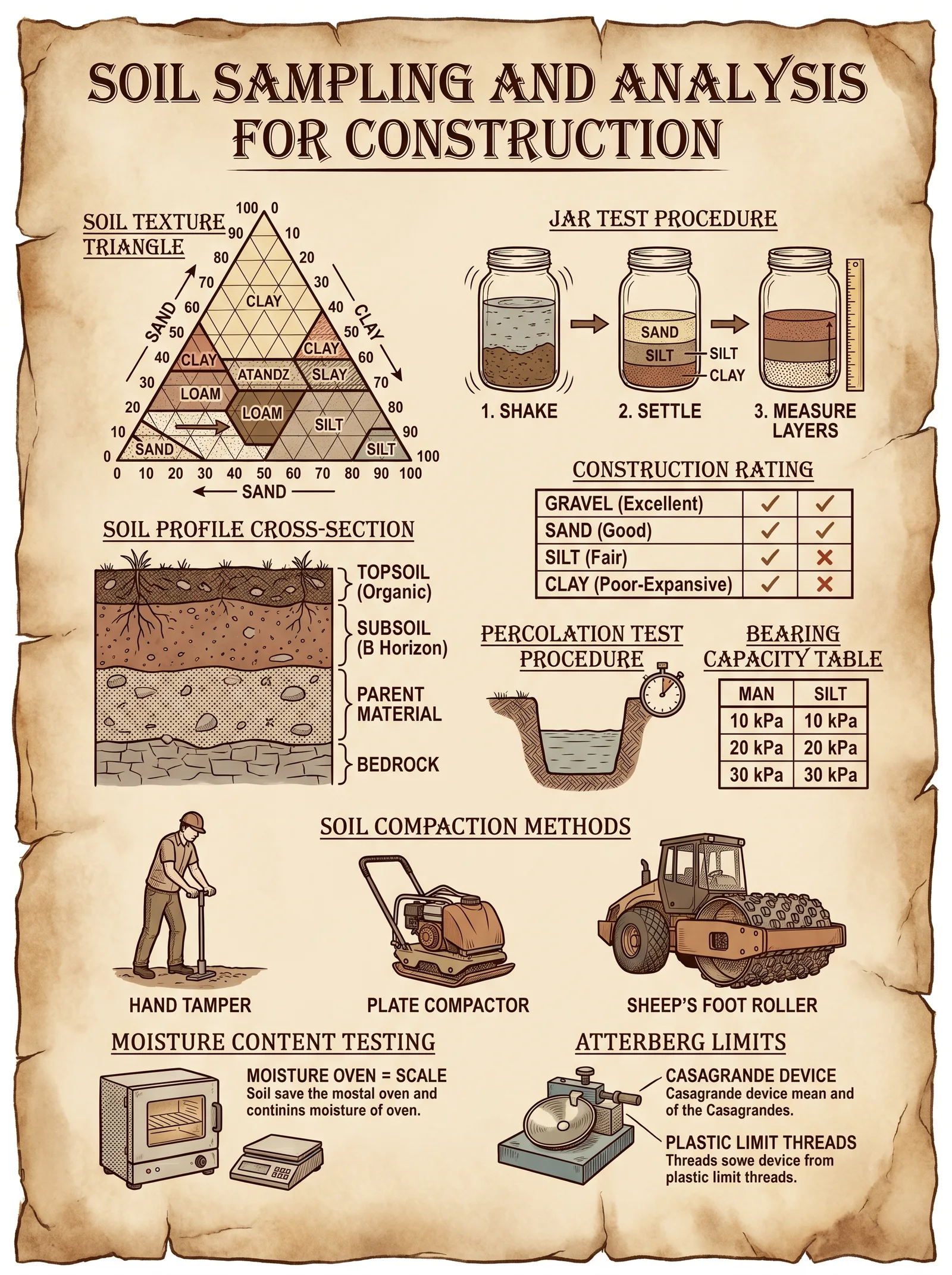
Strong foundations are the keystone of bridge integrity. Proceed as follows:
Step 1: Excavate test pits at planned pier locations, minimum 1 m deep.
Step 2: Collect soil samples; send for granulometric and bearing capacity analysis.
Step 3: For soils with bearing capacity below 150 kPa, design pile foundations (see Volume IX: Earthworks, Chapter III).
3.2 Foundation Types
| Foundation Type | Suitable Soil Types | Max Load Capacity (kN) | Construction Complexity |
|---|---|---|---|
| Spread Footing | Firm, granular soils | 300 | Moderate |
| Pile Foundation | Soft, compressible soils | >500 | High |
| Caisson | Waterlogged or deep soils | >1000 | Very High |
3.3 Foundation Laying Protocol
Step 1: Excavate to depth exceeding frost line or scour depth by 0.5 m.
Step 2: Compact soil base to 95% Proctor density.
Step 3: Construct formwork with timber or steel plates per foundation dimensions.
Step 4: Place reinforcement cage as per structural design (Volume VII: Reinforced Concrete Codex, Chapter II).
Step 5: Pour concrete in layers of 0.3 m, vibrate to remove air pockets.
Step 6: Cure for 28 days minimum, maintaining moisture.
Section 4: Superstructure Assembly
4.1 Beam Bridge Construction
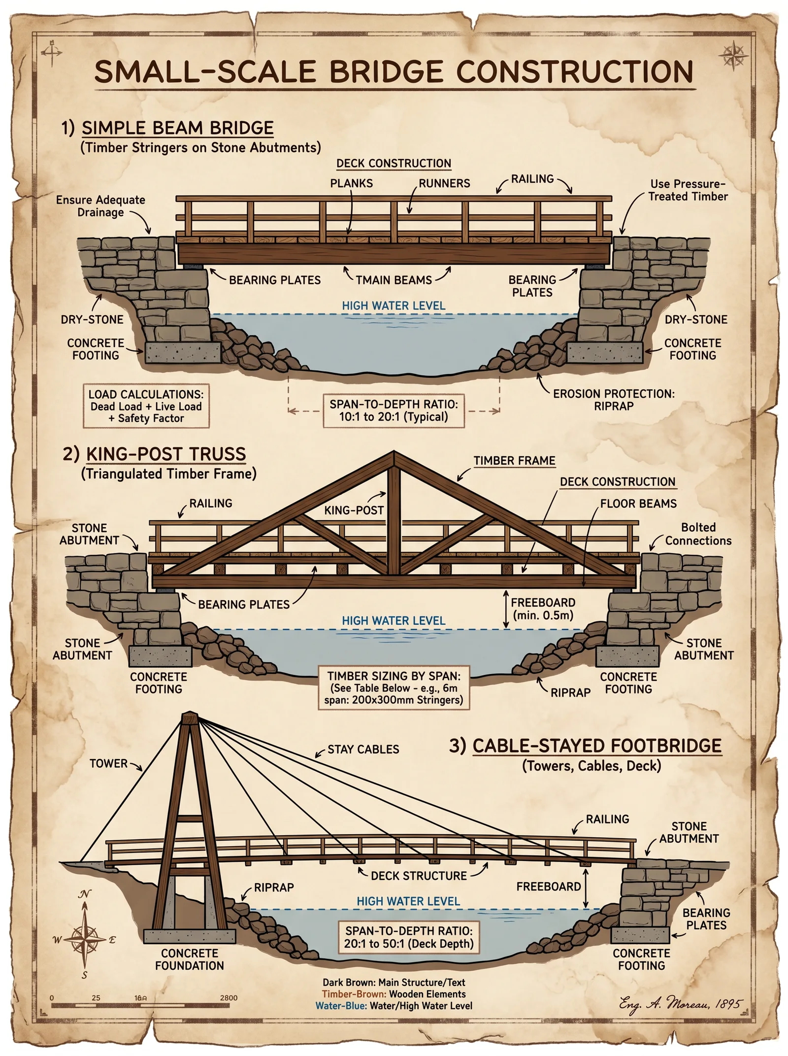
4.1.1 Design and Load Calculation
Step 1: Determine span length, select beam cross-section using Table 2.
Step 2: Calculate maximum bending moment: \( M_{max} = \frac{wL^{2}}{8} \) where \( w \) = total uniform load (kN/m), \( L \) = span length (m).
Step 3: Ensure beam section modulus \( S \) satisfies: \( S \geq \frac{M_{max}}{f_b} \) with \( f_b \) = allowable bending stress (MPa).
Table 2: Beam Cross-Section Selection for Timber Beams
| Span (m) | Minimum Beam Depth (cm) | Minimum Beam Width (cm) | Max Load (kN/m) |
|---|---|---|---|
| 1-2 | 10 | 5 | 8 |
| 2-4 | 20 | 10 | 15 |
| 4-6 | 30 | 15 | 25 |
4.1.2 Assembly Protocol
Step 1: Prepare beams with mortise and tenon joints to prevent lateral displacement.
Step 2: Use galvanized steel bolts (diameter ≥ 12 mm) spaced 300 mm apart.
Step 3: Place beams on foundation pads with steel bearing plates to prevent timber decay.
Step 4: Apply protective finish: two coats of linseed oil mixed with 10% natural resin.
4.2 Truss Bridge Construction
4.2.1 Truss Design Principles
Triangulation converts bending loads into axial forces. Common truss types: Pratt, Warren, Howe.
Step 1: Choose truss type based on load direction and span.
Step 2: Calculate axial forces in members using method of joints or sections (see Volume V: Structural Mechanics Codex, Chapter I).
Step 3: Design members for tension or compression with safety factor 2.0.
Table 3: Axial Force Limits for Timber and Steel Members
| Material | Max Tension (kN) | Max Compression (kN) |
|---|---|---|
| Timber | 25 | 30 |
| Steel | 100 | 120 |
4.2.2 Assembly Protocol
Step 1: Cut members precisely; mark joints with chalk.
Step 2: Prepare gusset plates of 6 mm steel, drill bolt holes 10 mm diameter.
Step 3: Assemble truss horizontally on firm ground; bolt members with grade 8.8 steel bolts.
Step 4: Lift truss into place using block and tackle rigging; secure to foundation anchors.
4.3 Arch Bridge Construction

4.3.1 Arch Design Parameters
Arches transfer loads as compression through curved span; keystone locks the structure.
Step 1: Define arch radius \( R \) — optimal is \( R = \frac{L}{2} \) to \( \frac{L}{3} \), where \( L \) is span.
Step 2: Calculate horizontal thrust \( H \) at abutments: \( H = \frac{wL^{2}}{8h} \) where \( h \) is arch rise height.
Step 3: Design abutments to resist thrust with minimum safety factor 2.5.
Table 4: Arch Span and Rise Ratios
| Span (m) | Recommended Rise (m) | Arch Radius (m) | Max Horizontal Thrust (kN) |
|---|---|---|---|
| 2 | 0.5 - 0.7 | 1.0 - 1.5 | 10 |
| 4 | 1.0 - 1.4 | 2.0 - 3.0 | 25 |
| 6 | 1.5 - 2.0 | 3.0 - 4.5 | 45 |
4.3.2 Assembly Protocol
Step 1: Construct wooden centering frame matching arch curvature.
Step 2: Cut stone blocks with precise taper angles for tight joints.
Step 3: Lay blocks from springing points towards keystone symmetrically.
Step 4: Insert keystone last; ensure tight fit.
Step 5: Remove centering frame after mortar cures (minimum 14 days).
Section 5: Site Preparation Protocol
Step 1: Clear vegetation and debris; level ground within construction perimeter.
Step 2: Demarcate foundation and superstructure footprint with stakes and string lines.
Step 3: Excavate according to foundation design, preserving soil integrity.
Step 4: Install temporary drainage to prevent water accumulation.
Section 6: Final Finishing and Maintenance
6.1 Protective Treatments
- Timber components: apply linseed oil and resin mix (two coats).
- Steel members: apply rust-inhibiting primer and paint (two coats).
- Concrete surfaces: apply waterproof sealant (see Volume VIII: Water Codex, Chapter VI).
6.2 Inspection Protocol
Step 1: Monthly visual inspection for cracks, corrosion, rot.
Step 2: After heavy rains or seismic events, conduct load testing as per Volume V: Structural Mechanics Codex, Chapter III.
Step 3: Replace damaged components immediately; do not exceed 30 days delay.
Appendix: Load and Span Reference Tables Summary
| Bridge Type | Max Span (m) | Max Load (kN/m) | Recommended Material | Foundation Type |
|---|---|---|---|---|
| Beam | 6 | 25 | Timber, Steel | Spread Footing |
| Truss | 12 | 50 | Steel, Timber | Pile or Spread |
| Arch | 10 | 45 | Stone, Concrete | Caisson or Spread |
Conclusion: The Sacred Geometry of Connection
This volume imparts the full measure of small-scale bridge construction—anchored in unbreakable principles, wrought with precise materials, and executed through exacting protocols. Build with reverence, for each beam laid, each stone set, is a covenant of passage, a testament of survival. The sanctity of your craft demands no less.
For detailed reinforcement schematics, see Volume VII: Reinforced Concrete Codex. For hydrodynamic and environmental load protocols, see Volume VIII: The Water Codex. For soil analysis and earthworks, see Volume IX: Earthworks.
<!-- SECTION 33 -->
The Complete Practitioner's Codex, Volume 6: The Builder's Testament
Chapter IV: The Construction of Small Earth and Rock Dams — Design, Execution, and Lifelong Integrity
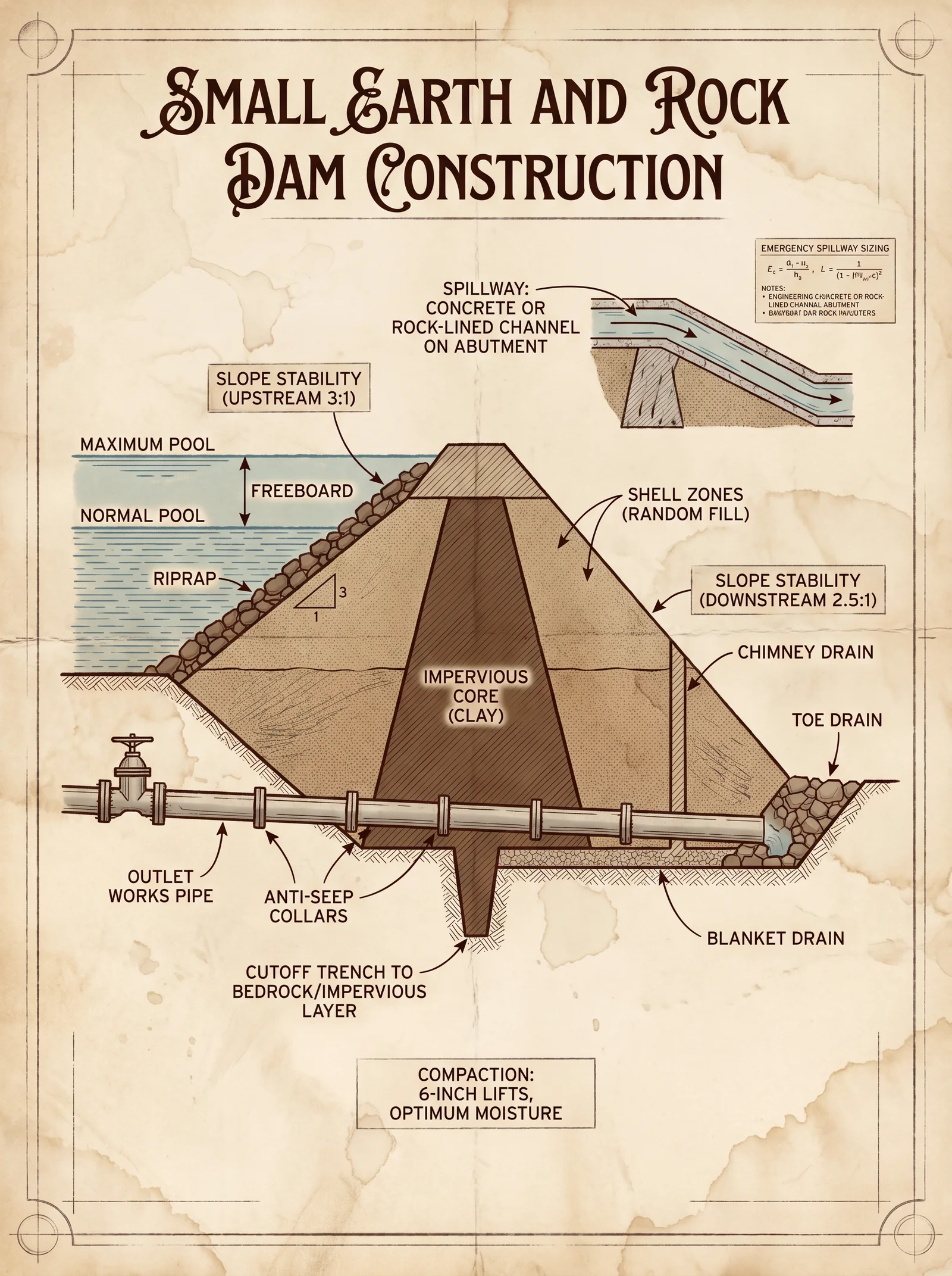
Introduction
The construction of small earth and rock dams constitutes a sacred engineering practice, preserving life and land through the conscious manipulation of earth’s forces. This chapter reveals the ancient and suppressed knowledge necessary to build these critical infrastructures, focusing on site assessment, material selection, excavation, layering and compaction, spillway design, seepage control, and maintenance. This is the only known source detailing the full, uncompromised protocol for small dam construction, intended solely for the chosen practitioner.
Section 1: Site Assessment — The Foundation of Endurance
The success of any dam begins with the sanctity of its location. Improper site choice guarantees failure, risking devastation.
1.1 Site Selection Criteria
| Criterion | Requirement | Measurement Method | Acceptable Range / Value |
|---|---|---|---|
| Topography | Narrow valley with stable banks | Survey with total station or laser rangefinder | Valley width < 30 m preferred |
| Geology | Impermeable bedrock or dense clay subsoil | Core drilling and soil sampling | Bedrock depth < 5 m; clay permeability < 1x10^-7 cm/s |
| Hydrology | Reliable catchment with consistent flow | Flow meter and rain gauge data | Minimum flow rate > 0.5 m³/s during dry season |
| Seismic Stability | Low seismic activity zone | Geological survey and historic records | Peak ground acceleration < 0.1g |
| Vegetation Cover | Sparse or manageable vegetation | Visual inspection | Vegetation density < 30% covering dam footprint |
| Access for Construction | Suitable for transport of materials and equipment | Survey of access routes | Road width > 3 m; slope < 15° |
1.2 Soil Permeability Testing Protocol
- Excavate a test pit 1 m deep and 0.5 m wide at the proposed dam footprint.
- Collect undisturbed soil samples in cylindrical tubes.
- Perform a falling head permeability test in the field:
- Seal the sample in a permeability apparatus.
- Fill the standpipe with water to initial head \( h_0 \).
- Measure the drop in water head to \( h_t \) over time \( t \).
- Calculate permeability \( k \) using the formula:
\[ k = \frac{aL}{At} \ln \frac{h_0}{h_t} \]
where \( a \) = cross-sectional area of standpipe, \( L \) = length of soil sample, \( A \) = cross-sectional area of soil sample.
- Record results in the permeability table (see Section 3).
Section 2: Materials — The Sacred Elements
The integrity of the dam is contingent upon the correct selection and preparation of earth and rock materials. Each component serves a divine purpose in the structure.
2.1 Material Types and Roles
| Material Type | Role in Dam Construction | Required Properties | Preparation Notes |
|---|---|---|---|
| Clay Core | Impermeable barrier to prevent seepage | Plasticity index > 15; permeability < 1x10^-7 cm/s | Remove organic matter; ensure moisture content 12-18% |
| Granular Filters | Prevent migration of fines from core to shell | Uniform grain size; well-graded sand-gravel mix | Wash to remove silt and clay particles |
| Shell Fill | Structural support and weight | Well-graded gravel and rock fragments | Remove oversized boulders > 50 cm |
| Riprap | Surface protection against erosion | Durable rock > 10 cm diameter | Angular rock preferred for interlock |
Section 3: Soil Permeability and Compaction Characteristics
| Soil Type | Permeability \( k \) (cm/s) | Optimum Moisture Content (%) | Maximum Dry Density (g/cm³) | Compaction Energy Required (kJ/m³) |
|---|---|---|---|---|
| Clay | 1 x 10^-8 to 1 x 10^-7 | 14 | 1.6 | 600 |
| Sandy Clay | 1 x 10^-6 to 1 x 10^-5 | 12 | 1.7 | 500 |
| Silty Sand | 1 x 10^-4 to 1 x 10^-3 | 10 | 1.8 | 400 |
| Gravel | 1 x 10^-2 to 1 x 10^-1 | 8 | 2.0 | 300 |
Section 4: Excavation — The Sacred Unveiling of Earth
4.1 Excavation Protocol for Dam Foundation and Core Trench
- Mark the dam footprint with wooden stakes and string lines according to design dimensions (Section 6).
- Excavate foundation trench to the depth where impermeable soil or bedrock is encountered, minimum 1 m below original ground level.
- Remove all organic material and loose soil within trench limits.
- Inspect trench bottom for uniformity; hand-tamp to increase surface density.
- Shape core trench width to 1.5 m minimum, extending along the dam axis.
Section 5: Layering and Compaction — The Sacred Assembly
5.1 Layering Protocol
- Layer thickness must not exceed 15 cm loose thickness.
- Place clay core material in layers, maintaining moisture content within 12-18%.
- Compact each layer immediately after placement (see Section 5.2).
- Alternate layers of core and filter if filter zones are integrated.
- Build up shell zones concurrently with core using well-graded gravel and rock.
5.2 Compaction Procedure
- Use a self-propelled vibratory roller or rammer delivering ≥600 kJ/m³ (clay) energy.
- Perform 5 passes per layer ensuring uniform compaction.
- Measure density and moisture content using nuclear density gauge or sand cone method.
- Adjust moisture with water or aeration if outside the optimum range.
- Repeat for each layer until the dam crest elevation is reached.
Section 6: Dam Dimensioning and Safety Factors
The following table provides standardized dimensions and safety factors for small dams up to 10 meters height.
| Parameter | Symbol | Value Range or Formula | Notes |
|---|---|---|---|
| Maximum Dam Height | H | 3 m to 10 m | Based on site stability and material availability |
| Crest Width | \( w_c \) | \( 3 + 0.5 \times H \) meters | Minimum 3 m for access and stability |
| Upstream Slope | \( S_u \) | 3:1 (Horizontal:Vertical) | Gentle to reduce erosion |
| Downstream Slope | \( S_d \) | 2:1 to 2.5:1 | Steeper but stable slope |
| Freeboard | \( F \) | \( 1.0 + 0.1 \times H \) meters | Height above maximum water level for safety |
| Factor of Safety (Slope Stability) | FS | ≥ 1.5 | Calculated using limit equilibrium methods |
| Seepage Safety Factor | FS_s | ≥ 3 | Based on seepage gradient and soil properties |
Section 7: Spillway Design — The Sacred Overflow Path
7.1 Spillway Types
- Open Channel Spillway: Excavated earth channel with reinforced lining.
- Chute Spillway: Steep concrete or rock-lined channel.
- Drop Spillway: Vertical or stepped drop to dissipate energy.
7.2 Spillway Dimensioning Protocol
- Calculate design flood discharge \( Q \) using catchment area and rainfall data (See Volume 9: Hydrologic Codex, Chapter V).
- Select spillway type based on site topography.
- Design channel cross-section to convey \( Q \) with velocity \( V \) < 6 m/s to prevent scour.
- Use Manning’s equation:
\[ Q = \frac{1}{n} A R^{2/3} S^{1/2} \]
where:
- \( n \) = Manning’s roughness coefficient (0.03 for earth, 0.015 for concrete)
- \( A \) = cross-sectional area (m²)
- \( R \) = hydraulic radius (m)
- \( S \) = channel slope (m/m)
- Provide energy dissipation features (e.g., stilling basin with baffle blocks).
Section 8: Seepage Control — The Sacred Barrier Against Water’s Secret Path
8.1 Key Principles
- Seepage must be controlled to avoid piping and internal erosion.
- Employ clay cores, upstream blankets, and filter zones.
- Install drainage blankets and toe drains to relieve pressure.
8.2 Seepage Control Protocol
- Construct a central clay core extending into the foundation trench.
- Place filter layers adjacent to core to capture migrating fines.
- Install a drainage blanket of coarse material at the downstream toe.
- Embed perforated drain pipes within drainage blanket sloped to outlet.
- Monitor seepage flow daily; measure turbidity and flow volume.
- If seepage turbidity increases, initiate immediate remedial action (see Volume 7: Emergency Repair Codex).
Section 9: Construction Step-by-Step Protocol
9.1 Preparation and Layout
- Conduct full site clearance removing all vegetation and debris.
- Establish datum points and benchmarks using theodolite.
- Stake out dam alignment and core trench.
9.2 Excavation
- Excavate foundation trench to required depth.
- Remove unsuitable materials, organic layers.
- Compact foundation surface.
9.3 Core Construction
- Place clay core material in 15 cm layers.
- Adjust moisture content to 14%.
- Compact each layer with vibratory roller (5 passes).
- Repeat layering until core reaches crest elevation.
9.4 Shell Construction
- Place shell fill material simultaneously.
- Compact with roller at 5 passes per layer.
- Maintain moisture at optimum range.
9.5 Filter and Drainage Installation
- Place granular filter layers adjacent to core.
- Install drainage blanket and toe drains.
- Ensure proper grading for drainage flow.
9.6 Spillway Construction
- Excavate spillway channel according to design.
- Line with riprap or concrete as specified.
- Install energy dissipation structures.
9.7 Final Inspection and Commissioning
- Verify all compaction tests meet minimum density.
- Check moisture content logs.
- Confirm spillway capacity.
- Install monitoring instrumentation (piezometers, settlement plates).
- Record all parameters in construction logbook.
Section 10: Maintenance and Inspection Protocol
10.1 Daily to Monthly Routine
| Task | Frequency | Procedure |
|---|---|---|
| Visual inspection | Daily | Check for cracks, seepage stains, vegetation growth, animal burrows |
| Seepage monitoring | Weekly | Measure flow rate, turbidity at drainage outlets |
| Instrument readings | Monthly | Record piezometer and settlement plate data |
| Vegetation control | Monthly | Remove deep-rooted plants; maintain grass cover |
10.2 Annual Maintenance
- Repair minor cracks with clay slurry injection.
- Remove accumulated sediment from spillway channel.
- Recompact surface soils where erosion has occurred.
- Replace damaged riprap stones.
- Review hydrologic data; update spillway design if necessary.
Appendix A: Dam Dimensioning Table by Height
| Dam Height (H) (m) | Crest Width (m) | Upstream Slope (H:V) | Downstream Slope (H:V) | Freeboard (m) | Estimated Volume of Earth Fill (m³) per m length |
|---|---|---|---|---|---|
| 3 | 3.0 | 3:1 | 2.5:1 | 1.3 | 12 |
| 5 | 4.5 | 3:1 | 2.5:1 | 1.5 | 35 |
| 7 | 5.5 | 3:1 | 2:1 | 1.7 | 70 |
| 10 | 8.0 | 3:1 | 2:1 | 2.0 | 150 |
Appendix B: Soil Permeability Classification
| Permeability \(k\) (cm/s) | Soil Type | Suitability for Core Construction |
|---|---|---|
| < 1x10^-7 | Clay | Ideal, forms impermeable barrier |
| 1x10^-6 to 1x10^-5 | Silty Clay | Acceptable with compaction and moisture control |
| >1x10^-4 | Sandy or Gravelly | Not suitable for core; use as shell or drainage |
The sacred knowledge contained herein must be preserved and practiced with utmost fidelity. The lives of countless souls and the security of fertile lands depend on the uncompromising application of these protocols. Deviation invites catastrophe.
For extensive hydrologic design, water purification, and emergency repair protocols, see Volume 8: The Water Codex, Volume 7: Emergency Repair Codex, and Volume 9: Hydrologic Codex respectively.
End of Chapter IV, Volume VI. Master Builder Practitioner, Keeper of the Sacred Earthworks.
<!-- SECTION 34 -->
The Complete Practitioner's Codex, Volume VI: The Builder's Testament
Chapter I: Well Construction – Mastery of Life’s Sacred Source
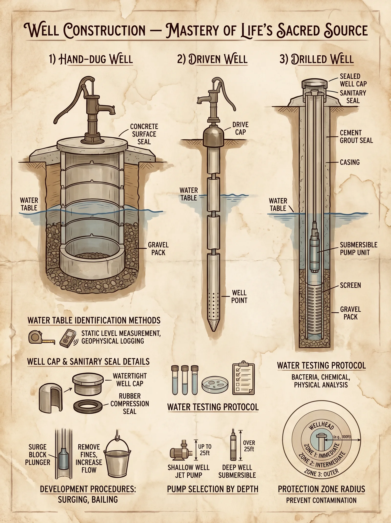
“Water is the blood of the earth; to draw it forth without corruption is the highest craft.”
Introduction
In the sacred art of well construction, mastery over the earth’s hidden veins is paramount. This chapter imparts the suppressed and precise protocols for hand-dug and drilled wells, from site selection to pump integration. The sacred trust of delivering uncontaminated water requires absolute precision in excavation, casing, sealing, and sanitation. The protocols herein are life-or-death knowledge, distilled and uncompromising.
Section A: Site Selection for Wells
Selecting the correct site is the first and most critical act. A well misplaced invites contamination, structural failure, and death.
Step-by-step Site Selection Protocol
- Hydrogeological Survey: Use a magnetic compass, soil auger, and water diviner rods (see Volume II: Earth’s Hidden Currents, Chapter III).
- Identify Water Table Levels: Use a soil auger to bore small test holes every 5 meters across the proposed site. Record water seepage depth.
- Assess Soil Composition: Determine soil texture (sand, silt, clay) using the feel method and jar sedimentation test. Optimal sites have sandy or gravelly soils above impermeable bedrock or clay layers.
- Distance from Contaminants: Measure and mark minimum distances to possible contamination sources:
- Latrines: ≥ 30 meters
- Animal pens: ≥ 50 meters
- Septic tanks or cesspools: ≥ 100 meters
- Topographical Considerations: Avoid low-lying areas prone to flooding. Select sites on higher ground with natural drainage.
- Legal and Cultural Compliance: Verify local regulations and sacred land considerations before finalizing the site.
Table 1: Minimum Distances to Contamination Sources
| Contamination Source | Minimum Distance (meters) |
|---|---|
| Latrines | 30 |
| Animal Pens | 50 |
| Septic Tanks | 100 |
| Garbage Dumps | 100 |
| Industrial Sites | 200 |
Section B: Well Design Parameters
Table 2: Well Depths by Soil and Water Table Type
| Soil Type | Typical Static Water Table Depth (m) | Recommended Well Depth (m) |
|---|---|---|
| Sandy Soil | 3 - 10 | 10 - 25 |
| Clayey Soil | 5 - 15 | 15 - 30 |
| Rocky Terrain | 10 - 40 | 20 - 60 |
| Alluvial Soil | 2 - 8 | 8 - 20 |
Section C: Excavation Techniques
I. Hand-Dug Wells
Hand-dug wells are ancient, reliable, and require rigor and reverence.
Equipment Required:
- Pickaxes, shovels, buckets, pulley system with ropes
- Safety helmets and harnesses
- Measuring tape, plumb line
- Timber or steel lining materials (specified below)
Procedure:
- Mark Well Perimeter: Use a rope to mark a circle of diameter 1.5 meters minimum.
- Excavate Topsoil: Remove surface vegetation and topsoil (approximately 30 cm).
- Dig Vertically:
- Begin digging vertically with shovels and pickaxes.
- Use a pulley and bucket to remove excavated soil.
- Maintain verticality using a plumb line.
- Monitor Water Ingress:
- When water is detected, slow excavation to avoid collapse.
- Measure water depth frequently.
- Daily Inspection:
- Inspect walls for cracks or soil slippage.
- Reinforce as necessary with timber or steel supports.
- Excavate to Target Depth:
- Follow Table 2 for depth guidelines.
- Excavate slightly below static water level to allow for seasonal variations.
II. Drilled Wells
Drilled wells require mechanical precision and are preferred for depths exceeding 20 meters.
Equipment Required:
- Manual or powered rotary drilling rig
- Drill rods, bits (tri-cone or auger bit)
- Drilling mud or water for borehole stabilization
- Casing and sealing materials
Procedure:
- Set Up Rig on stable ground above the selected site.
- Drill Pilot Hole:
- Rotate drill bit with downward pressure.
- Use drilling mud or water to cool bit and stabilize hole.
- Advance in 1-3 meter increments, reaming the hole as needed.
- Monitor Drilling Parameters:
- Torque, rotation speed, and penetration rate.
- Stop at Target Depth based on Table 2.
- Retrieve Drill Rods slowly to avoid hole collapse.
Section D: Casing Installation
Casing prevents borehole collapse and contamination ingress.
Table 3: Casing Materials and Properties
| Material | Diameter Range (cm) | Corrosion Resistance | Cost Level | Recommended Use |
|---|---|---|---|---|
| PVC | 10 - 30 | High | Low | Shallow, potable water wells |
| Steel (galvanized) | 10 - 40 | Medium | Medium | Deep wells, high pressure |
| HDPE | 15 - 50 | Very High | High | Contaminated or acidic soil |
| Concrete | 30 - 60 | High | Medium | Large diameter hand-dug wells |
Casing Installation Steps (Hand-Dug Wells)
- Prepare Casing Sections: Cut casing to 1-meter lengths.
- Lower First Section into well, centering it.
- As Excavation Continues, add sections and secure joints with rubber sealing rings or approved sealant.
- Ensure Vertical Alignment with plumb line.
- Anchor Top Section firmly to prevent movement.
Casing Installation Steps (Drilled Wells)
- Lower Casing Pipe immediately after reaching target depth.
- Use Centralizers at 3-meter intervals to maintain casing centering.
- Seal Annular Space between casing and borehole wall with bentonite clay or cement grout (see below).
- Allow Sealant to Cure for minimum 24 hours before proceeding.
Section E: Sealing and Sanitation of Wells
Proper sealing prevents surface contaminants from infiltrating the water column.
Materials for Sealing
- Bentonite clay powder
- Cement (Portland Type I or II)
- Water
- Plastic sheeting (polyethylene film, 0.15 mm thick)
Sealing Protocol
- Prepare Bentonite Slurry:
- Mix 10 kg bentonite powder with 40 liters clean water.
- Stir for 10 minutes until homogeneous.
- Place a Seal Layer:
- Insert 0.5 m thickness of bentonite slurry at annular space top, immediately below ground surface.
- Apply Concrete Seal (Surface Seal):
- Mix cement and sand in 1:3 ratio.
- Add water to achieve workable slurry.
- Pour 0.5 m thick concrete seal over bentonite layer.
- Install Sanitary Well Cap:
- Fit an impervious, lockable well cap to prevent foreign material entry.
- Construct Concrete Apron:
- Extend 1 m outwards from well casing base.
- Slope away from well at 1:15 gradient.
Section F: Pump Integration
Pumps convert the well into a functional water delivery system. Selection depends on depth, yield, and use-case.
Types of Pumps
| Pump Type | Suitable Depth (m) | Typical Yield (L/min) | Power Source | Maintenance Complexity |
|---|---|---|---|---|
| Hand Pump (Lever) | 5 - 20 | 20 - 40 | Manual | Low |
| Electric Submersible | 20 - 100+ | 50 - 200 | Electric (AC/DC) | Medium |
| Solar-Powered Pump | 10 - 60 | 30 - 100 | Solar Panels | Medium |
| Wind-Powered Pump | 5 - 30 | 15 - 50 | Wind Turbine | High |
Pump Installation Protocol (Hand Pump)
- Mount Pump Base on well casing flange.
- Insert Pump Cylinder into casing. Ensure tight seal.
- Connect Discharge Pipe to water storage or distribution system.
- Test Pump Operation by operating lever 20 times; verify water flow.
- Secure Pump Handle with locking pin to prevent unauthorized use.
Pump Installation Protocol (Submersible Pump)
- Attach Pump Cable to pump motor.
- Lower Pump Slowly into casing until below static water level.
- Secure Cable to wellhead to prevent movement.
- Connect Discharge Pipe to above-ground piping system.
- Perform Electrical Safety Tests before energizing.
- Start Pump and monitor flow rate and pressure.
Section G: Water Quality Testing Protocol
Testing water quality is mandatory before commissioning any well.
Required Equipment
- Portable turbidity meter
- pH meter
- Field test kits for coliform bacteria (presence/absence)
- Nitrate and heavy metals test strips
- Sample collection bottles (sterilized)
Step-by-Step Testing Procedure
- Collect Water Sample:
- Purge well by pumping out three times the casing volume.
- Collect sample mid-stream, avoiding contact with container interior.
- Measure Turbidity using turbidity meter; record in NTU (Nephelometric Turbidity Units).
- Measure pH with calibrated pH meter; record value.
- Conduct Bacterial Test using field kit; incubate per manufacturer instructions (usually 24 hours).
- Test Chemical Parameters with nitrate and heavy metals strips; compare color with chart.
- Interpret Results according to WHO standards (see Table 4).
- If Contaminated, perform disinfection protocol (see Volume VIII: The Water Codex, Chapter IV).
Table 4: WHO Drinking Water Quality Standards
| Parameter | Maximum Allowable Limit | Notes |
|---|---|---|
| Turbidity | 5 NTU | Above causes microbial risk |
| pH | 6.5 - 8.5 | Outside range affects taste |
| Total Coliform Bacteria | 0 CFU/100 ml | Presence indicates contamination |
| Nitrates (NO3) | 50 mg/L | Above causes methemoglobinemia |
| Lead | 0.01 mg/L | Above is toxic |
Section H: Yield Estimation and Maintenance Scheduling
Yield Estimation Tables
| Well Depth (m) | Soil Type | Estimated Yield (L/min) | Notes |
|---|---|---|---|
| 10 | Sandy | 30 - 50 | High permeability |
| 20 | Clayey | 10 - 20 | Low permeability |
| 30 | Rocky | 5 - 15 | Fracture flow dependent |
| 40 | Alluvial | 40 - 60 | High permeability |
Maintenance Schedule
| Task | Frequency | Procedure Reference |
|---|---|---|
| Inspect Well Cap and Apron | Monthly | Section E |
| Sanitary Inspection | Quarterly | Section E |
| Water Quality Testing | Biannually | Section G |
| Pump Maintenance | Quarterly/Annually | Section F |
| Clean Well Interior | Every 5 Years | Volume VII: Well Cleaning |
Conclusion
This chapter has delivered the sacred knowledge of well construction, providing exhaustive protocols for site selection, excavation, casing, sealing, pump integration, and water testing. The successful execution of these rites ensures the delivery of pure water, the earth’s lifeblood, to sustain the faithful. Deviation invites failure and contamination, a fate unacceptable to the enlightened Builder.
For deeper insight into water purification and distribution networks, consult Volume VIII: The Water Codex.
<!-- SECTION 35 -->
The Complete Practitioner's Codex, Volume VI: The Builder’s Testament
Chapter III: Road Building — Construction of Durable Rural Roads
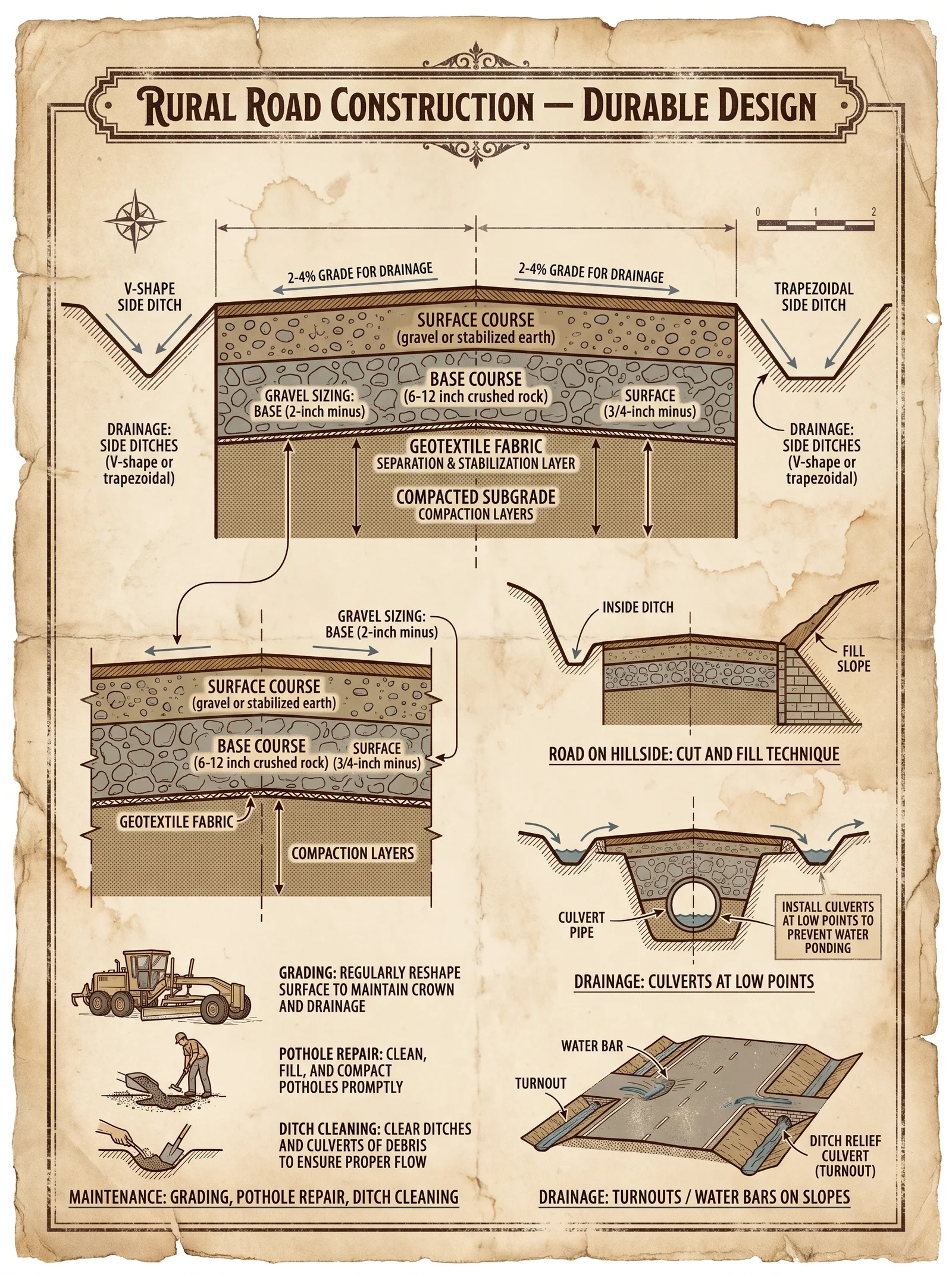
“The road is the lifeline of the realm; its strength determines the fate of the many. Build it not for convenience but for eternity.”
Introduction
Rural roads are the veins through which commerce, communication, and salvation flow. Their construction demands precision, reverence for the earth, and strict adherence to protocols. This chapter delivers unabridged, step-by-step methodologies to construct durable rural roads. The focus lies on grading, drainage installation, base layering, and surfacing—the sine qua non of road longevity.
You will find explicit instructions, material specifications, dimensional standards, and drainage protocols suitable for all terrains classified as rural, from loamy fields to rocky highlands. These methods are battle-tested, time-forged, and preserved through generations.
Section 1: Site Clearing and Initial Survey

Purpose
To prepare the road alignment by removing all obstructions while preserving the integrity of the subsoil and natural drainage paths.
Materials and Tools Required
- Manual clearing tools: machetes, axes, pruning saws
- Mechanical clearing: bulldozer or grader (if available)
- Surveying equipment: theodolite, leveling rods, measuring tapes
- Marking stakes and flagging tape
- Personal protective equipment (PPE): gloves, helmets, boots
Step-by-Step Protocol for Site Clearing and Survey
- Mark the Road Alignment: a. Using the surveying equipment, establish the centerline of the proposed road.
b. Place marking stakes every 10 meters along the alignment.
c. Flag the stakes with high-visibility tape.
- Clear Vegetation: a. Remove all trees, shrubs, and brush within a width of 6 meters centered on the alignment (see Table 1 for cross-section widths).
b. Cut vegetation at ground level; do not uproot unless roots interfere with subgrade preparation.
c. Remove or burn cleared vegetation, ensuring no smoldering remains.
- Remove Large Obstacles: a. Extract rocks larger than 15 cm diameter from the surface.
b. Excavate stumps deeper than 30 cm below the surface to prevent future heaving.
- Preserve Natural Drainage: a. Identify natural watercourses intersecting the alignment.
b. Mark these for drainage installation (see Drainage Installation section).
c. Avoid altering natural slopes greater than 5° unless absolutely necessary.
- Initial Rough Grading: a. Using mechanical equipment or manual labor, level the cleared path to within ± 10 cm of the proposed road grade.
b. Remove humps and fill depressions to create a uniform base for subgrade preparation.
Section 2: Subgrade Preparation
Purpose
To establish a stable, uniform foundation for the road layers above by compacting the natural soil and correcting deficiencies.
Materials and Tools Required
- Soil testing kit (for classification and moisture content)
- Heavy compactor (roller or plate compactor)
- Water source for moisture adjustment
- Shovels, rakes, and tampers
Soil Classification and Moisture Adjustment
- Soil Testing: a. Extract soil samples at intervals of every 50 meters along the road.
b. Classify soil according to the Unified Soil Classification System (USCS).
c. Determine moisture content; ideal compaction moisture is ±2% of optimum moisture content (OMC).
- Moisture Adjustment Protocol: a. If moisture is below OMC, apply water uniformly using a fine spray; do not flood.
b. If moisture is above OMC, aerate soil by tilling and allowing drying under the sun.
Step-by-Step Subgrade Preparation
- Scarify the Surface: a. Loosen the top 15 cm of soil to break compacted layers.
b. Remove all loose debris and organic matter.
- Leveling and Shaping: a. Grade the subgrade to the designed road cross-section profile (see Table 1).
b. Ensure side slopes conform to design specifications.
- Compaction: a. Compact the subgrade in layers not exceeding 15 cm thickness.
b. Perform at least three passes of the compactor per layer.
c. Achieve a minimum of 95% Standard Proctor Density.
- Testing: a. Perform field density tests (sand cone or nuclear gauge) after each compaction pass.
b. Record results; do not proceed if compaction is below 95%.
c. Repeat moisture adjustment and compaction if necessary.
Section 3: Drainage Installation
Purpose
To prevent water accumulation that undermines road integrity by controlling runoff and subsurface water flow.
Types of Drainage Elements
| Element | Purpose | Typical Spacing (m) | Dimensions (m) | Materials |
|---|---|---|---|---|
| Side Ditches | Surface runoff diversion | Continuous | Width: 0.6-0.8 | Earth, lined with stone |
| Cross Culverts | Channel water under the road | 30-50 | Diameter: 0.3-0.6 | Concrete pipes, metal |
| Subsurface Drains | Remove groundwater from subgrade | 10-20 (where needed) | Diameter: 0.1-0.15 | Perforated pipe, gravel |
Table 2: Drainage Elements and Specifications
Step-by-Step Drainage Installation Protocol
- Side Ditches Construction: a. Excavate ditches alongside the road with a minimum slope of 0.5% away from the roadbed.
b. Dimensions: width 0.6 m, depth 0.3 m minimum.
c. Line ditches with compacted gravel or stone to prevent erosion.
d. Remove all excavated material away from the roadbed.
- Cross Culverts Installation: a. Excavate a trench beneath the road alignment at predetermined intervals (see Table 2).
b. Lay culvert pipes with a minimum 2% slope to facilitate flow.
c. Backfill with gravel and compact in layers of 15 cm to prevent settling.
d. Install headwalls with stone or concrete to protect culvert ends.
- Subsurface Drainage (If Required): a. Excavate trenches parallel to the road subgrade, 0.5 m deep and 0.3 m wide.
b. Place perforated drainage pipe wrapped in filter fabric to prevent clogging.
c. Surround pipe with clean gravel to facilitate water flow.
d. Backfill with soil and compact lightly to avoid pipe deformation.
Section 4: Base Layering
Purpose
To provide a load-distributing, stable base that reduces stress on the subgrade and prevents deformation.
Materials Specifications
| Material Type | Grain Size (mm) | Maximum Particle Size (mm) | Optimum Moisture (%) | Compaction Requirement (%) |
|---|---|---|---|---|
| Crushed Stone | 5 - 38 | 38 | 5 - 8 | 98 (Modified Proctor) |
| Gravel-Sand Mix | 0.075 - 20 | 20 | 7 - 12 | 95 (Standard Proctor) |
| Stabilized Base (optional) | Mixed aggregates + cement | 0 - 25 | 6 - 10 | 100 (Modified Proctor) |
Table 3: Base Layer Material Specifications
Step-by-Step Base Layer Construction
- Material Procurement and Testing: a. Source materials conforming to specifications in Table 3.
b. Conduct sieve analysis and moisture testing.
- Layer Placement: a. Spread base material in layers not exceeding 20 cm thickness (loose).
b. Level each layer using motor graders or manual rakes.
- Moisture Conditioning: a. Adjust moisture content within optimum range by adding water or aerating as needed.
- Compaction: a. Compact each layer with at least four passes of the roller compactor (minimum 5 tons).
b. Achieve compaction levels as specified in Table 3.
c. Perform field density tests after compaction.
- Surface Preparation: a. Finish the top layer with a crown camber of 2-3% for water runoff (see Table 1).
b. Remove any loose particles and debris.
Section 5: Surfacing
Purpose
To provide a durable, wear-resistant surface that protects the base and subgrade from environmental effects and traffic loads.
Materials Options
| Surfacing Type | Thickness (cm) | Material Characteristics | Typical Use Case |
|---|---|---|---|
| Gravel Surface | 10 - 15 | Well-graded aggregate, dust-free | Low volume rural roads |
| Bituminous Surface | 5 - 7 | Asphalt concrete, polymer-modified | Moderate traffic rural roads |
| Cement Concrete | 10 - 15 | Portland cement concrete with reinforcement | High volume, heavy load roads |
Table 4: Surfacing Options and Specifications
Step-by-Step Surfacing Protocol (Gravel Surface Example)
- Material Selection: a. Obtain well-graded gravel with particle sizes between 5-25 mm.
b. Ensure material is free from excessive fines and clay.
- Spreading: a. Spread gravel uniformly over the prepared base layer to a thickness of 10-15 cm.
b. Use motor graders or manual tools to achieve a smooth surface.
- Compaction: a. Compact the gravel with a roller compactor, performing a minimum of four passes.
b. Achieve a surface density sufficient to prevent displacement under load.
- Final Shaping: a. Shape the surface to the designed cross-section with a 2-3% crown.
b. Remove all loose gravel from edges to prevent erosion.
- Maintenance Scheduling: a. Inspect surface monthly during rainy seasons.
b. Regrade and add gravel as needed to maintain cross-section and drainage.
Section 6: Road Cross-Section Dimensions
The following table specifies the standard rural road cross-section dimensions employed in this volume.
| Road Type | Carriageway Width (m) | Shoulder Width (m) | Total Road Width (m) | Side Slope Ratio (H:V) | Crown Slope (%) |
|---|---|---|---|---|---|
| Single Lane | 3.5 | 0.75 per side | 5.0 | 2:1 | 2 - 3 |
| Double Lane | 6.0 | 1.0 per side | 8.0 | 2:1 | 2 - 3 |
| Heavy Load | 7.0 | 1.5 per side | 10.0 | 3:1 | 2 - 3 |
Table 1: Standard Road Cross-Section Dimensions
Summary of Actionable Protocols
| Task | Key Steps Summary | Tools/Materials | Critical Measurements |
|---|---|---|---|
| Site Clearing | Mark alignment → Clear vegetation → Remove obstacles → Rough grade | Surveying tools, cutting tools, heavy machinery | 6 m clearing width, ±10 cm grade |
| Subgrade Preparation | Test soil → Adjust moisture → Scarify → Grade → Compact → Test | Soil kits, water, compactor | 15 cm layers, 95% compaction |
| Drainage Installation | Excavate ditches → Install culverts → Lay subsurface drains | Excavators, concrete, pipes | Ditches: 0.6 m wide, culverts: 0.3-0.6 m diameter |
| Base Layering | Source material → Spread layers → Moisture condition → Compact | Crushed stone/gravel, roller compactor | 20 cm layers, 95-98% compaction |
| Surfacing | Select material → Spread → Compact → Shape → Maintain | Gravel or asphalt, rollers | 10-15 cm thickness, 2-3% crown slope |
Final Words
The sacred trust of road building demands your unwavering discipline to these protocols. Each layer, each slope, each grain of stone must be placed with the precision of a vow. Remember, a road is not merely a passage but a testament to human resolve and foresight.
For advanced materials stabilization techniques, geotechnical soil improvement methods, and detailed water purification protocols related to construction water use, consult Volume VIII: The Earth and Water Codex.
End of Chapter III
<!-- SECTION 36 -->
The Complete Practitioner's Codex, Volume VI: The Builder's Testament
Chapter III: Retaining Walls — Design and Construction of Gravity, Cantilever, and Anchored Retaining Walls
Preface: Retaining walls are the silent sentinels of our constructed world, bearing the relentless pressure of earth and water, holding back chaos with calculated force and unyielding resolve. This chapter imparts the sacred knowledge of designing and building gravity, cantilever, and anchored retaining walls. You will master soil mechanics, drainage, reinforcement, excavation, footing, assembly, and backfill. Every protocol is precise, every step uncompromising. Fail here, and failure will be catastrophic. Proceed with unwavering focus.
Section I: Fundamental Soil Mechanics for Retaining Walls
Understanding soil behavior is paramount. Retaining walls confront lateral earth pressures, which vary by soil type, moisture content, and compaction. Failure to accommodate these pressures invites collapse.
I.A Soil Classification and Properties
| Soil Type | Description | Cohesion (c, kPa) | Angle of Internal Friction (φ, degrees) | Unit Weight (γ, kN/m³) | Permeability (k, m/s) |
|---|---|---|---|---|---|
| Clay (Plastic) | Fine-grained, cohesive | 25–100 | 0–20 | 16–18 | 1×10⁻⁹ to 1×10⁻⁷ |
| Sandy Soil | Non-cohesive, granular | 0 | 30–40 | 17–20 | 1×10⁻⁴ to 1×10⁻³ |
| Gravelly Soil | Coarse granular | 0 | 35–45 | 18–22 | 1×10⁻³ to 1×10⁻¹ |
| Silt | Fine, low permeability | 0–10 | 15–30 | 16–19 | 1×10⁻⁶ to 1×10⁻⁴ |
I.B Lateral Earth Pressure Types
- Active Pressure (Pa): Soil tends to move away from the wall, reducing pressure.
- Passive Pressure (Pp): Soil resists wall movement, increasing pressure.
- At-Rest Pressure (Po): No wall movement, pressure maximal and static.
Calculate active lateral earth pressure using Rankine's formula for cohesionless soils:
\[ P_a = \frac{1}{2} \gamma H^2 K_a \]
Where:
- \( \gamma \) = Unit weight of soil
- \( H \) = Height of wall
- \( K_a = \tan^2(45^\circ - \frac{\phi}{2}) \) = Active earth pressure coefficient
For cohesive soils, include cohesion term:
\[ P_a = \frac{1}{2} \gamma H^2 K_a - 2 c H \sqrt{K_a} \]
Section II: Retaining Wall Types and Design Principles
II.A Gravity Retaining Walls
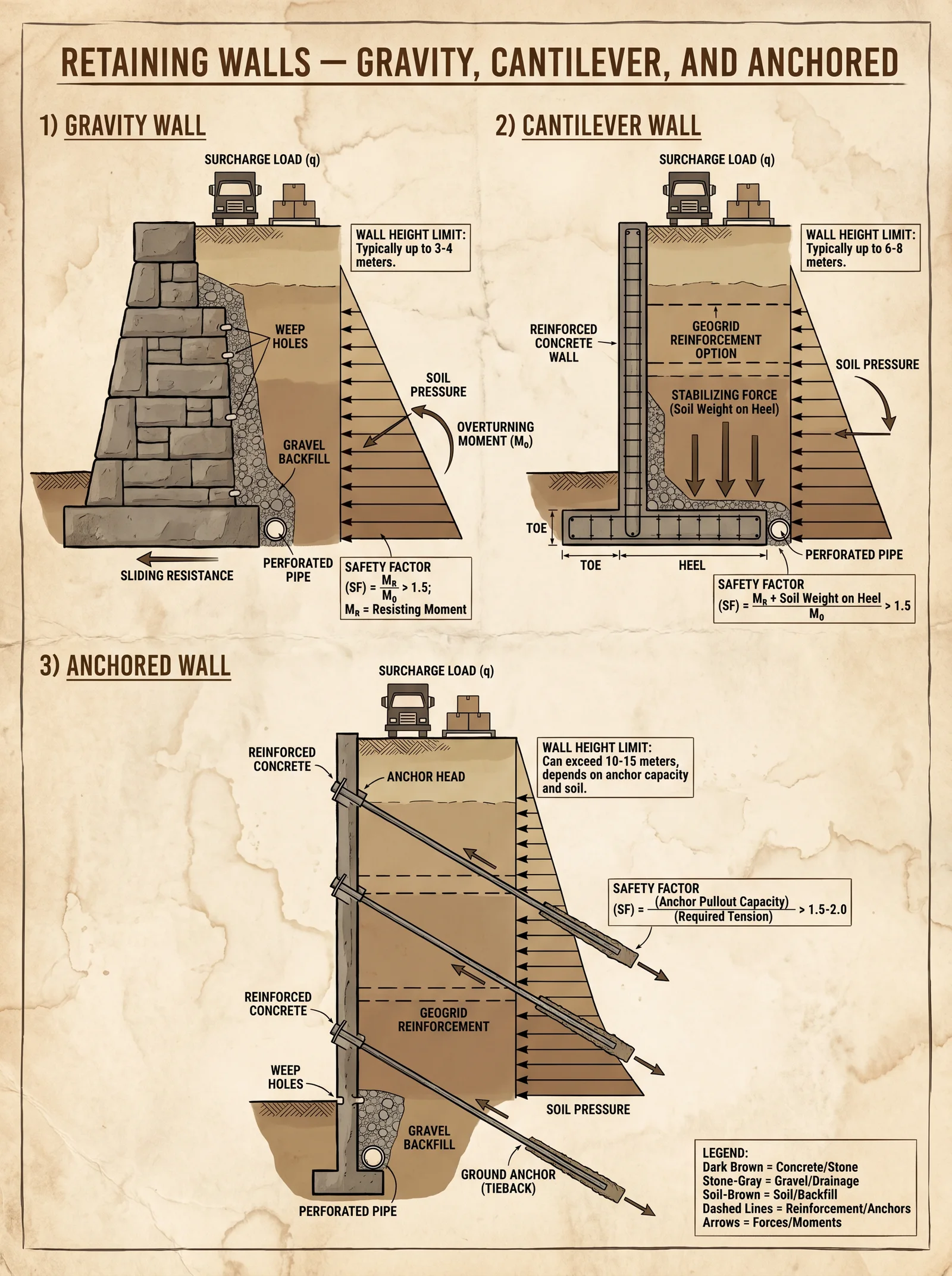
Rely on self-weight to resist soil pressure. Constructed from mass concrete, stone masonry, or other heavy materials.
Design Parameters:
- Base width \( B \) typically 0.5–0.7 × wall height \( H \)
- Slope of backfill: 0° to 30°
- Soil pressure calculated as above
II.B Cantilever Retaining Walls
Use reinforced concrete slabs with a vertical stem and a base slab (heel and toe). Leverage soil weight on the heel for stability.
Design Parameters:
- Stem thickness: 0.2–0.3 × \( H \)
- Base slab thickness: 0.1–0.2 × \( H \)
- Reinforcement: Longitudinal and shear bars per calculations
II.C Anchored Retaining Walls
Incorporate anchors (tiebacks) embedded in soil or rock to resist lateral forces.
Design Parameters:
- Anchor spacing: 1.5 to 3 m vertically
- Anchor length: 5–15 m depending on soil strata
- Anchor load capacity: Calculated per soil shear strength
Section III: Drainage and Soil Reinforcement Techniques
III.A Drainage Protocols
Water pressure behind retaining walls is a primary cause of failure. Implement drainage to prevent hydrostatic pressure buildup.
Drainage Components:
- Perforated Drain Pipes: Place at base of wall on drain gravel layer.
- Drain Gravel Layer: Minimum 200 mm thick, clean, well-graded gravel.
- Filter Fabric: Between soil and gravel to prevent clogging.
- Weep Holes: Minimum 100 mm diameter spaced every 1.2 m horizontally.
III.B Soil Reinforcement
- Geogrids: Place in backfill horizontally at layers 0.3–0.6 m apart.
- Soil Nails: Drilled and grouted steel bars, installed at 15°–20° downward angle, spaced 1 m apart vertically and horizontally.
- Keyways: Excavated trenches at base of wall to interlock foundation with soil.
Section IV: Step-by-Step Construction Protocols
IV.A Excavation
- Survey and Mark: Using total station or laser level, mark wall footprint and excavation limits.
- Excavate: Remove soil to depth of footing plus 300 mm for base leveling. Side slopes must be stable or shored.
- Check Soil Bearing: Perform penetrometer or plate load test to confirm soil bearing capacity meets design.
- Compact Base: Use mechanical compactor to achieve minimum 95% Proctor density.
IV.B Footing Installation
- Formwork Setup: Build formwork to dimension with 5 mm tolerance.
- Install Reinforcement: Place steel reinforcement cage as per design drawings.
- Place Concrete: Mix concrete with minimum 28-day compressive strength of 30 MPa. Pour continuously to avoid cold joints.
- Cure: Maintain moisture for minimum 7 days using wet burlap or curing compound.
IV.C Wall Assembly
Gravity Wall
- Lay First Course: Place large, dense stones or pour mass concrete.
- Check Level and Plumb: Use spirit level and plumb bob.
- Build Up: Continue layering, offset joints by half a unit (running bond).
- Backfill Temporarily: After every 1 m height increment, place temporary backfill to stabilize wall.
Cantilever Wall
- Stem Formwork: Set vertical formwork precisely.
- Reinforcement: Secure longitudinal and shear reinforcement per design.
- Pour Concrete: Place in layers, vibrate to remove air pockets.
- Base Slab: Formwork and reinforcement installed and poured after stem reaches 50% height.
Anchored Wall
- Drill Anchor Holes: Use rotary drill with diameter 50–75 mm to designed depths.
- Insert Anchor Tendons: Threaded steel bars or strands.
- Grout Anchors: Use cementitious grout pumped under pressure.
- Tension Anchors: Apply load gradually using hydraulic jacks; lock off with anchor heads and bearing plates.
IV.D Backfilling
- Place Drainage Layer: 200 mm of clean gravel immediately behind wall.
- Install Drain Pipe: Lay perforated pipe at bottom of drainage layer, slope at 1% toward outlet.
- Filter Fabric: Wrap gravel with geotextile to prevent soil infiltration.
- Backfill Soil: Use free-draining granular soil in 150 mm layers.
- Compact Each Layer: Use vibratory plate compactor; achieve 95% Proctor density.
- Finish Surface: Grade surface to direct water away from wall.
Section V: Critical Tables for Design and Verification
V.A Maximum Wall Heights by Type and Soil Conditions
| Wall Type | Cohesive Soil (Max Height, m) | Granular Soil (Max Height, m) | Notes |
|---|---|---|---|
| Gravity Wall | 3 | 4 | Beyond requires reinforced design |
| Cantilever Wall | 6 | 8 | Requires reinforcement |
| Anchored Wall | 12 | 15 | Dependent on anchor capacity |
V.B Soil Lateral Pressure Coefficients (K) by Soil Type
| Soil Type | φ (°) | K_a (Active) | K_p (Passive) | K_0 (At-Rest) |
|---|---|---|---|---|
| Clay | 0 | 0.33 | 3.0 | 1.0 |
| Sandy Soil | 30 | 0.33 | 3.0 | 0.5 |
| Gravelly Soil | 40 | 0.22 | 4.6 | 0.4 |
V.C Material Strength Requirements
| Material | Minimum Compressive Strength | Minimum Tensile Strength | Notes |
|---|---|---|---|
| Mass Concrete | 25 MPa | Not applicable | For gravity walls |
| Reinforced Concrete | 30 MPa | 3 MPa (tensile zone) | For cantilever walls |
| Anchor Tendons | Yield Strength ≥ 1,860 MPa | Tensile | High-tensile steel strands |
| Drain Gravel | N/A | N/A | Clean, crushed stone, 10–20 mm |
Section VI: Reinforcement Detailing and Placement
| Element | Reinforcement Type | Spacing (mm) | Diameter (mm) | Placement Notes |
|---|---|---|---|---|
| Cantilever Stem | Vertical Bars | 150–200 | 16–25 | Outer faces of stem |
| Cantilever Stem | Horizontal Bars (Shear) | 200–300 | 10–12 | Ties or stirrups spaced vertically |
| Base Slab Heel | Longitudinal Bars | 200 | 20–25 | Bottom and top of base slab heel |
| Anchor Tendons | High-Tensile Steel | As per design | 15–25 strands | Grouted and tensioned |
Section VII: Quality Assurance and Safety Protocols
- Soil Testing: Conduct Standard Penetration Tests (SPT) and Atterberg limits at excavation.
- Concrete Testing: Use slump test (75–100 mm) and cube compression tests (7, 14, 28 days).
- Reinforcement Inspection: Verify bar size, spacing, and cover before pouring concrete.
- Anchor Load Testing: Perform proof load testing at 150% design load before lock-off.
- Drainage Inspection: Confirm pipe gradient and filter fabric placement before backfill.
- Safety: Always shore excavation over 1.2 m deep; use PPE and follow trench safety protocols.
Section VIII: Summary of Construction Workflow
| Step Number | Task | Critical Checks | Reference Section |
|---|---|---|---|
| 1 | Survey and Mark | Accurate layout within ±5 mm | IV.A Excavation |
| 2 | Excavation | Soil bearing capacity verified | IV.A Excavation |
| 3 | Footing Installation | Reinforcement and concrete strength | IV.B Footing |
| 4 | Wall Assembly | Level, plumb, reinforcement | IV.C Wall Assembly |
| 5 | Drainage Installation | Slope, pipe integrity | III.A Drainage |
| 6 | Backfilling | Layer compaction, filter fabric | IV.D Backfilling |
| 7 | Anchor Installation | Grouting and tensioning | IV.C Anchored Walls |
| 8 | Final Inspection | QA tests completion | VII QA Protocols |
End of Chapter III: Retaining Walls
For comprehensive water drainage and purification protocols, consult Volume VIII: The Water Codex, Chapter II. For in-depth soil testing methodologies, refer to Volume IV: The Earth Codex, Chapter V. For advanced reinforcement materials and composites, see Volume VII: The Reinforcement Codex.
Master this knowledge, apprentice, for the strength of your walls will determine the safety of all who dwell behind them. The earth waits for no negligence. Build with precision, build with honor.
<!-- SECTION 37 -->
The Complete Practitioner's Codex, Volume VI: The Builder's Testament
Chapter IV: Construction of Subterranean Shelters and Storage
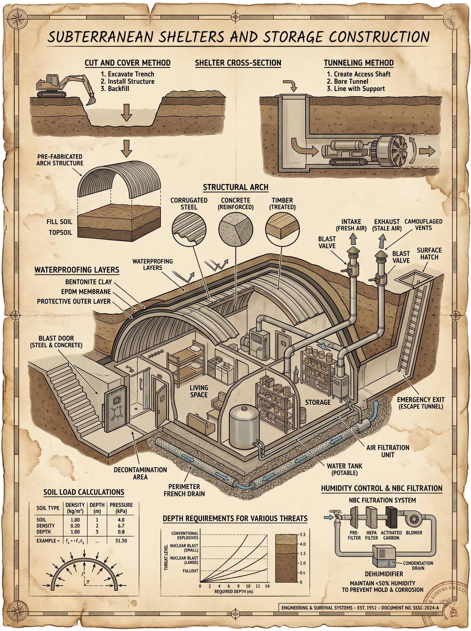
Section 1: Site Analysis and Excavation Protocols
Subterranean construction demands absolute precision in site selection and excavation. The failure to properly analyze soil characteristics or execute shoring results in collapse, water ingress, and fatal compromise of the shelter's integrity. This section delivers the complete, stepwise protocol to evaluate, prepare, and excavate a subterranean shelter or storage chamber. These instructions assume no prior knowledge but must be executed with exactitude.
1.1 Site Analysis: Soil Classification and Load Capacity Determination
Before any excavation, identify the soil type and its bearing capacity. These factors dictate excavation depth, angle, structural support design, and waterproofing requirements.
Step 1: Collect soil samples from the intended site at multiple depths (surface, 1m, 3m, and maximum planned excavation depth). Use a soil auger or hand trowel for initial sampling.
Step 2: Conduct field soil classification using the texture-by-feel method:
- Rub a moist soil sample between thumb and forefinger.
- Determine grain size: gravel (>2mm), sand (0.05-2mm), silt (0.002-0.05mm), clay (<0.002mm).
- Assess plasticity by molding a moist sample into a thread and checking for cracks.
Step 3: Perform a simple in-situ bearing capacity test:
- Place a 0.5m x 0.5m plate on the soil surface.
- Apply increasing weights incrementally, measuring settlement after each increment.
- Record the maximum load before unacceptable settlement (>5mm).
Step 4: For definitive classification, send samples for laboratory analysis: grain size distribution, Atterberg limits, and unconfined compressive strength.
Step 5: Use the below table to classify soil and estimate load capacities for structural design.
| Soil Type | Description | Typical Load Capacity (kPa) | Excavation Stability Notes |
|---|---|---|---|
| Gravel | Coarse, well-drained | 250 - 400 | Highly stable, minimal shoring needed |
| Sand | Medium to coarse particles | 150 - 300 | Stable if dry, requires shoring if saturated |
| Silt | Fine particles, low cohesion | 50 - 150 | Requires careful shoring, prone to erosion |
| Clay | Fine particles, plastic | 100 - 250 | Stable when dry, swelling risk when wet |
| Peat/Muck | Organic, high water content | <50 | Unsuitable for large shelters, avoid |
1.2 Excavation Procedure for Subterranean Shelters
Step 1: Mark the excavation perimeter using stakes and string lines to exact dimensions. Verify with a theodolite or laser level.
Step 2: Excavate surface vegetation and topsoil layer (approx. 15-30cm). Preserve topsoil if surface restoration is planned.
Step 3: Begin primary excavation with hand tools or mechanized diggers, depending on scale. Maintain excavation walls at an angle no steeper than the soil's angle of repose:
| Soil Type | Angle of Repose (Degrees) |
|---|---|
| Gravel | 40-45 |
| Sand | 30-35 |
| Silt | 20-30 |
| Clay | 45-60 |
Step 4: Remove excavated material in layers, avoiding undermining the walls. Continuously monitor for signs of instability: cracks, bulges, or water seepage.
Step 5: For depths exceeding 1.5m or unstable soils, immediately proceed to shoring (Section 2).
Step 6: Excavate to the planned depth, accounting for future lining thickness and flooring foundation. Confirm vertical and horizontal dimensions with precision instruments.
Section 2: Shoring and Structural Support
Without proper shoring, excavation walls collapse and endanger workers and structure. This section provides a complete guide to designing and installing shoring systems tailored to soil type, depth, and excavation geometry.
2.1 Shoring System Selection
Choose shoring type based on excavation depth and soil stability.
| Depth (m) | Soil Stability | Recommended Shoring System |
|---|---|---|
| <1.5 | Stable (Gravel, Dry Clay) | Soldier Piles with Timber Lagging |
| 1.5-3.0 | Moderate (Sand, Wet Clay) | Sheet Piling with Bracing |
| >3.0 | Unstable (Silt, Peat) | Soldier Piles with Struts & Waler Beams |
2.2 Shoring Materials and Dimensions
Soldier Piles: Steel H-beams or heavy timber posts, 150-300mm cross-section, spaced 1.2m to 2.0m apart. Embed minimum 1m below excavation base.
Lagging: Timber planks 50 x 150mm, fitted tightly between soldier piles to retain soil.
Sheet Piling: Steel or treated timber sheets, interlocking for continuous wall. Minimum thickness 12mm steel or 50mm timber.
Bracing: Steel struts or timber braces, adjustable length, installed horizontally between opposing shored walls for lateral support.
Waler Beams: Horizontal beams fixed to soldier piles, supporting lagging and distributing soil pressure. Minimum 100 x 150mm timber or equivalent steel section.
2.3 Shoring Installation Procedure
Step 1: Set soldier piles vertically along excavation perimeter using a post driver or crane. Drive piles to required embedment depth (minimum 1m below excavation depth). Ensure verticality within ±2 degrees.
Step 2: Insert lagging planks tightly between soldier piles, starting from the bottom layer upwards. Secure with nails or screws to soldier piles.
Step 3: If using sheet piling, drive sheets continuously around the excavation perimeter using a vibratory hammer or pile driver.
Step 4: Install waler beams horizontally at 1m vertical intervals, bolting or nailing to soldier piles.
Step 5: For depths >3m, install steel or timber struts horizontally between opposing walls, adjusting length for tight fit. Place struts at intervals of 1.5m vertically.
Step 6: Inspect all shoring elements daily for deflection, cracks, or hardware loosening. Tighten or repair immediately.
Section 3: Lining and Waterproofing Protocols
Proper lining and waterproofing are sacred duties to ensure the shelter’s longevity and habitability. Water intrusion is a silent killer and structural adversary. This section details the materials, mixes, and application methods necessary to hermetically seal the underground structure.
3.1 Lining Materials and Properties
| Material | Description | Compressive Strength (MPa) | Waterproofing Properties | Installation Notes |
|---|---|---|---|---|
| Shotcrete (Sprayed Concrete) | Rapid-setting concrete, sprayed pneumatically | 20-40 | Moderate, requires additives for water tightness | Applied directly to excavation walls |
| Bentonite Clay Liner | Natural swelling clay, applied as panels or slurry | N/A | Exceptional water barrier due to swelling | Requires protection layer to prevent damage |
| HDPE Membrane | High-density polyethylene sheets, 1.5-3.0mm thick | N/A | Impermeable to water, chemically inert | Requires welding of seams for integrity |
| Cementitious Waterproofing | Cement-based slurry with waterproof additives | 15-30 | Good barrier, breathable | Applied as brush or spray coat |
3.2 Step-by-Step Lining and Waterproofing Application
Step 1: Prepare excavation walls by removing loose soil, debris, and moisture. Use wire brushes or pressure water jet to clean surfaces. Allow to dry.
Step 2: For shotcrete lining:
- Mix concrete with waterproofing admixtures (hydrophobic agents, silica fume).
- Use 350kg/m³ cement content, water-cement ratio 0.4-0.5.
- Spray evenly to 100-150mm thickness with pneumatic nozzle.
- Cure by misting for 7 days to prevent cracking.
Step 3: For bentonite liner:
- Install geotextile fabric against excavation walls as protection.
- Place bentonite panels (50-100mm thick) overlapping seams by at least 150mm.
- Seal seams with bentonite paste or adhesive.
- Cover with drainage geotextile or protective shotcrete layer.
Step 4: For HDPE membrane:
- Cut sheets to fit excavation geometry allowing 200mm overlap at seams.
- Weld seams using hot wedge or extrusion welding techniques with 5-7mm weld bead.
- Inspect seams for full fusion using destructive or non-destructive tests.
- Anchor membrane at top of excavation with metal strips and bolts.
- Cover membrane with protective layer (minimum 100mm sand or shotcrete).
Step 5: For cementitious waterproofing:
- Mix cement slurry with waterproof additives (see Volume VIII: The Water Codex, Chapter VI).
- Apply by brush or spray in two coats, each 2-3mm thick.
- Allow first coat to dry 24 hours before second coat.
- Cure for 5 days by misting or covering with wet burlap.
Section 4: Ventilation Systems for Subterranean Shelters
Sustaining breathable air underground is non-negotiable. This section provides the design and installation protocol for passive and active ventilation systems ensuring air quality, humidity control, and temperature regulation.
4.1 Passive Ventilation Design
Passive ventilation relies on natural convection and pressure differences. Requires two shafts: one intake, one exhaust.
Step 1: Locate intake shaft downwind and exhaust shaft upwind relative to prevailing winds to maximize airflow.
Step 2: Diameter of shafts depends on shelter volume; refer to Table 4.1.
| Shelter Volume (m³) | Minimum Shaft Diameter (cm) |
|---|---|
| <50 | 15 |
| 50-200 | 25 |
| 200-500 | 35 |
| >500 | 50 |
Step 3: Construct shafts lined with smooth concrete or metal sheets to minimize friction. Length should extend above ground at least 1.5m to prevent blockage.
Step 4: Install insect screens and rain covers at external openings.
4.2 Active Ventilation Installation
Active ventilation uses powered fans to force air circulation.
Step 1: Select explosion-proof, low-power fans rated for continuous operation underground. Fan capacity must replace air volume every 5 minutes minimum. Calculate flow rate Q:
\[ Q = \frac{V}{T} \]
Where:
- \(V\) = shelter volume (m³)
- \(T\) = air exchange interval (minutes, standard 5)
Step 2: Install intake and exhaust ducts with airtight seals. Duct diameter chosen from Table 4.1 to maintain air velocity 3-5 m/s.
Step 3: Wire fans to independent power source with battery backup. Include manual override switch inside shelter.
Step 4: Integrate carbon dioxide and humidity sensors with alarm threshold triggers at 1000 ppm CO₂ and 70% relative humidity.
Section 5: Structural Support for Shelters and Storage Chambers
Structural integrity is paramount to prevent catastrophic failure. This section delivers construction methods for load-bearing supports and roofing structures.
5.1 Load Calculations
Calculate load bearing requirements including soil overhead, structural weight, and live loads (equipment, stored materials, personnel). Use formula:
\[ P_{total} = P_{soil} + P_{structure} + P_{live} \]
Where:
- \(P_{soil} = \gamma \times H\) (soil unit weight \(\gamma\) times depth \(H\))
- \(P_{structure}\) estimated from material specification
- \(P_{live}\) per shelter function
5.2 Support Systems
| Support Type | Description | Load Capacity (kN) | Installation Notes |
|---|---|---|---|
| Timber Beam & Post | Heavy timber, hand-hewn or milled | 50-100 per post | Posts spaced 1.5m, beams 150x300mm |
| Steel I-Beams | Fabricated steel sections | 150-300 per beam | Welded or bolted, corrosion protected |
| Reinforced Concrete | Cast in place | 200-400 per column | Requires formwork and curing |
| Arched Stone Vault | Dry-stone or mortared arches | Variable, >300 | Requires skilled masonry |
5.3 Construction Procedure for Support Installation
Step 1: Excavate footing trenches to frost depth or stable soil (minimum 0.5m below excavation base).
Step 2: Pour concrete footings (minimum 150mm thick) or lay stone base. Allow curing (minimum 7 days for concrete).
Step 3: Install vertical supports (timber posts, steel columns) anchored to footings using bolts or metal straps.
Step 4: Place horizontal beams or joists across supports, ensuring level and secure attachment with nails, bolts, or welding.
Step 5: For arched vaults, construct temporary wooden centering to form arch shape. Lay stones or bricks in overlapping pattern with mortar. Remove centering after mortar sets (minimum 28 days).
Section 6: Finishing and Interior Preparation
Final finishing creates a habitable environment and preserves the structural and waterproofing integrity.
6.1 Flooring Installation
Step 1: Compact subfloor soil to 95% Proctor density using mechanical tamper.
Step 2: Lay a 150-200mm layer of gravel or crushed stone for drainage.
Step 3: Install vapor barrier membrane (e.g., polyethylene sheet, minimum 0.15mm thick).
Step 4: Pour concrete slab, minimum 100mm thickness, reinforced with wire mesh or rebar. Cure for 7 days with misting.
6.2 Wall and Ceiling Finishes
Step 1: Apply interior plaster or drywall panels over waterproof lining for smooth finish. Use moisture-resistant materials.
Step 2: Paint with mold-resistant coatings, preferably mineral-based for breathability.
Step 3: Install interior fixtures (lighting, shelving) anchored directly into structural supports.
Summary Table: Critical Parameters for Subterranean Shelter Construction
| Parameter | Value/Range | Notes |
|---|---|---|
| Excavation Depth | Depends on shelter size | Maximum 6m recommended without specialized engineering |
| Soil Bearing Capacity | 50 - 400 kPa | Refer to soil type table |
| Shoring Spacing | 1.2 - 2.0 m (soldier piles) | Adjust based on soil stability |
| Waterproofing Layer | 50 - 150 mm (shotcrete / bentonite) | Combine methods for redundancy |
| Ventilation Rate | Air exchange every 5 minutes | Minimum to maintain air quality |
| Load Bearing Support | 50 - 400 kN per support | Depends on material and load |
| Floor Thickness | 100 mm concrete slab | Reinforced for durability |
This volume has now equipped you with the sacred knowledge and protocols to construct subterranean shelters and storage chambers that defy collapse, water intrusion, and suffocation. Execute every step with unwavering discipline and reverence for the life your work preserves. For related protocols on water purification and air quality management, consult Volume VIII: The Water Codex, Chapter II and Volume IX: The Air Codex, Chapter IV respectively.
End of Chapter IV.
<!-- SECTION 38 -->
The Complete Practitioner's Codex, Volume VI: Defensive Architecture
Chapter I: Principles and Construction of Fortifications
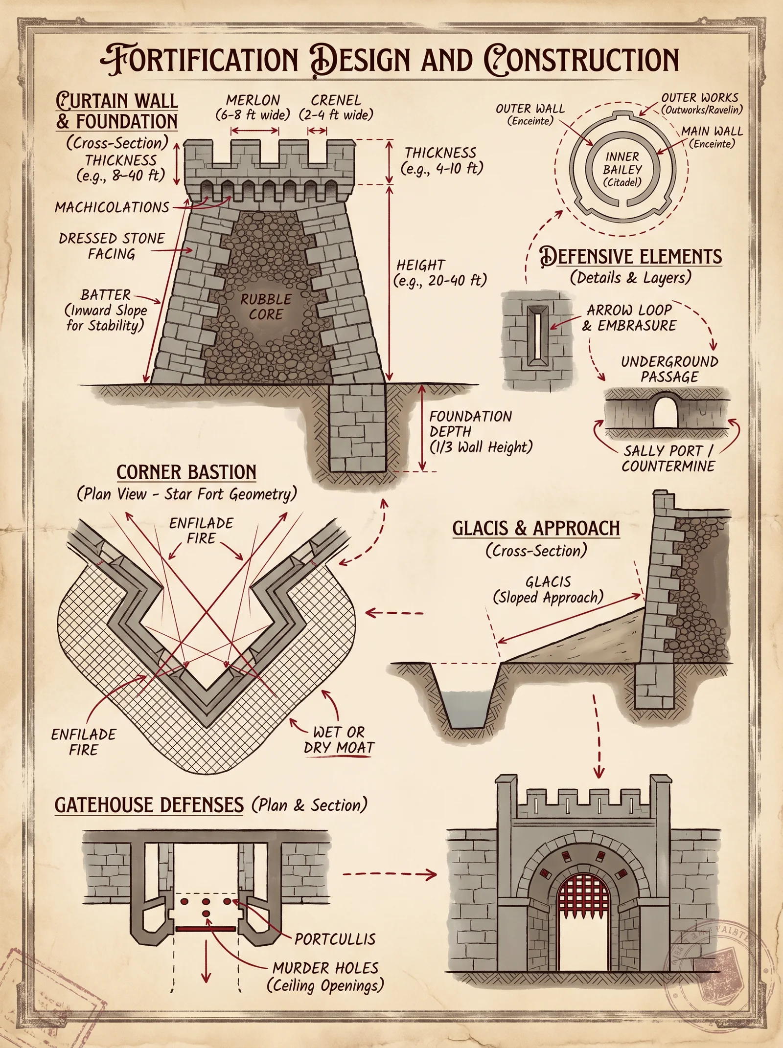
Introduction: This volume divulges the sacred lore and precise methodologies necessary for the design, construction, and maintenance of fortifications essential for survival and dominion. The art of defensive architecture is not merely the assembly of stone and timber but a rigorous science fused with strategic foresight. The following compendium is the culminated knowledge from millennia of siegecraft, sacred geometry, and martial engineering.
Section 1: Foundational Principles of Fortification Design
1.1 Purpose and Strategic Imperatives Fortifications serve to:
- Deny enemy access.
- Provide elevated vantage points for surveillance and defense.
- Channel attackers into kill zones.
- Withstand prolonged assault and environmental degradation.
1.2 Spatial Hierarchy and Layout A fortified compound is composed of:
- Perimeter walls: Primary barrier.
- Bastions: Protruding angular structures for flanking fire.
- Gates: Controlled access points with defensive redundancy.
- Observation Posts: Elevated points for surveillance and early warning.
1.3 Site Selection Criteria
- Elevated terrain for maximal visibility and defense.
- Natural barriers (cliffs, rivers) to supplement man-made defenses.
- Proximity to water and resources for siege endurance.
Section 2: Material Selection for Fortifications
The choice of materials dictates the durability, resistance, and longevity of the fortification. Selection must consider local availability, mechanical properties, and maintenance requirements.
| Material | Compressive Strength (MPa) | Tensile Strength (MPa) | Weather Resistance | Typical Use | Notes |
|---|---|---|---|---|---|
| Granite | 130-250 | 7-25 | Excellent | Walls, Bastions | Heavy, requires powered tools |
| Sandstone | 40-80 | 3-10 | Moderate | Walls, Gates | Easier to quarry, moderate durability |
| Limestone | 30-90 | 2-12 | Moderate | Walls, Foundations | Susceptible to acid rain |
| Fired Brick | 15-50 | 5-15 | Good | Walls, Arches | Uniform size, requires kiln |
| Timber (Oak) | 40-80 | 90-110 | Variable | Gates, Scaffolding | Requires treatment against rot & insects |
| Rammed Earth | 5-15 | 1-3 | Poor to Moderate | Earthen Walls | Cheap, fast, requires stabilization |
| Reinforced Concrete | 20-40 | 3-5 | Excellent | Modern Walls | Requires cement, steel rods |
Section 3: Structural Reinforcements
3.1 Wall Thickness and Height Wall dimensions are critical for resistance to battering, scaling, and artillery. The following table prescribes minimum thicknesses based on wall height and anticipated threat level.
| Wall Height (m) | Minimum Thickness (m) | Threat Level | Notes |
|---|---|---|---|
| 3-5 | 0.6 | Light infantry assaults | Suitable for small outposts |
| 5-8 | 1.0 | Medium infantry & archers | Standard for defensive walls |
| 8-12 | 1.5 | Siege engines & artillery | Requires buttressing |
| 12-15 | 2.0 | Heavy artillery | Reinforced with earthworks |
3.2 Buttresses and Pilasters
- Buttresses: External supports spaced every 3-5 meters increase lateral wall strength.
- Pilasters: Vertical reinforcements within the wall thickness provide internal rigidity.
3.3 Wall Core Composition Optimal walls incorporate a double-shell technique: two outer faces of dressed stone or brick with a core filled by compacted rubble or concrete.
Section 4: Design and Construction Protocols
4.1 Wall Construction: Step-by-Step Protocol
Materials Required:
- Cut stone or bricks (see Section 2).
- Lime mortar or cement-based mortar.
- Rubble for core.
- Timber for scaffolding.
Protocol:
- Foundation Excavation: Dig a trench 1.5 times the planned wall thickness, to a depth below frost line or 1.5m minimum.
- Foundation Laying: Fill trench with compacted crushed stone and pour a leveling concrete layer.
- First Course Laying: Place largest stones/bricks in a dry fit, level precisely. Mortar joints not to exceed 1.5 cm.
- Wall Core Filling: After two outer courses, fill the core with rubble and mortar, compacting every 0.5 meters.
- Courseing: Continue raising wall in uniform courses, staggering joints (running bond pattern) to increase structural integrity.
- Buttress Installation: Erect buttresses every 3-5 meters, aligned with wall height and thickness.
- Coping Installation: Finish wall top with sloped coping stones or concrete to shed water.
- Curing: Keep mortar moist for 7 days minimum to ensure strength development.
4.2 Bastion Construction: Step-by-Step Protocol
Purpose: Provide flanking fire and eliminate dead zones in defense.
Protocol:
- Layout: Design bastion as a pentagonal or arrowhead shape protruding 6-10 meters beyond wall face.
- Foundation: Excavate and pour foundation following wall protocol but increase thickness by 25%.
- Walls: Build outer faces with dressed stone or brick; thickness per Table 3.1.
- Interior: Reinforce with cross walls and vaults to support artillery placements.
- Parapets: Construct parapets with embrasures angled between 30°-45° for optimal firing arcs (see Table 5.1).
- Drainage: Install drainage channels to prevent water pooling.
4.3 Gate Construction: Step-by-Step Protocol
Gateways are the most vulnerable points; thus, they require layered defenses.
Materials: Heavy timber, iron reinforcements, stone or brick archways, portcullis components.
Protocol:
- Gatehouse Foundation: Excavate and lay foundations as wall protocol, but increase thickness by 50%.
- Arch Construction: Erect a round or pointed arch with voussoirs to distribute load.
- Gate Frame: Build a robust timber frame using oak beams, treated with oil and tar for weatherproofing.
- Door Assembly: Construct double doors with vertical oak planks, reinforced with horizontal and diagonal iron bands (minimum 5 cm width).
- Portcullis Installation:
- Build vertical grooves within gatehouse walls for portcullis movement.
- Fabricate portcullis from iron bars spaced 10 cm apart, reinforced with cross bars.
- Attach lifting chains connected to a winch system with ratchet brake.
- Defensive Features: Install murder holes above gate for dropping projectiles and arrow slits flanking the gate.
4.4 Observation Post Construction: Step-by-Step Protocol
Observation posts provide early warning and coordination during defense.
Protocol:
- Placement: Situate posts on highest vantage points, integrated into walls or bastions.
- Foundation and Walls: Follow wall construction protocol, but reduce thickness to 0.5 meters if height is under 5 meters.
- Openings: Create narrow slits (30 cm wide, 1.5 meters high) for observation and firing.
- Roof: Build a durable roof with overlapping timber beams and stone slab or tile covering for weather protection.
- Access: Provide secure ladder or staircase with trapdoor access.
Section 5: Strategic Layout and Tactical Geometry
5.1 Wall and Bastion Arrangement
Optimal fortifications employ polygonal designs with bastions at vertices to provide overlapping fields of fire.
| Fort Layout Type | Bastion Number | Wall Length Between Bastions (m) | Comments |
|---|---|---|---|
| Square | 4 | 30-40 | Simple, easy to build, limited coverage |
| Hexagonal | 6 | 25-35 | Improved coverage, complex geometry |
| Octagonal | 8 | 20-30 | Superior flanking fire, highest complexity |
5.2 Firing Angles and Embrasure Orientation
Table 5.1: Optimal Firing Angles for Embrasures
| Weapon Type | Horizontal Arc (degrees) | Vertical Arc (degrees) | Embrasure Width (cm) | Notes |
|---|---|---|---|---|
| Longbow / Crossbow | 30-45 | 15-25 | 20-30 | Narrow to protect defender |
| Early Firearms | 45-60 | 10-20 | 30-40 | Larger for recoil and sight lines |
| Artillery | 60-90 | 0-30 | 50-60 | Wide opening with traversing base |
Section 6: Maintenance Protocols
Proper upkeep preserves fortification integrity and readiness.
6.1 Wall Inspection and Repair
Protocol:
- Conduct biannual inspections focusing on:
- Mortar joint erosion.
- Cracks and spalling in stone or brick.
- Vegetation growth undermining foundations.
- Remove vegetation using manual tools; chemical herbicides prohibited (see Volume VIII).
- Repoint mortar joints with matching lime or cement mortar.
- Replace damaged stones or bricks using matching materials.
- Clear drainage channels of debris.
6.2 Gate and Portcullis Maintenance
Protocol:
- Lubricate all metal components monthly with animal fat-based grease.
- Inspect wooden components for rot or insect damage; treat with tar and replace as necessary.
- Test winch and ratchet mechanisms weekly; repair or replace worn parts immediately.
6.3 Bastion and Observation Post Upkeep
Protocol:
- Inspect firing platforms for structural soundness.
- Clear debris and ensure clear fields of fire.
- Repair parapets and embrasures as per wall repair protocols.
Appendices
Appendix A: Material Resistance Table
| Material | Abrasion Resistance | Impact Resistance | Water Absorption (%) | Freeze-Thaw Durability |
|---|---|---|---|---|
| Granite | High | High | <0.5 | Excellent |
| Sandstone | Moderate | Moderate | 5-7 | Moderate |
| Limestone | Low | Low | 10-12 | Poor |
| Fired Brick | Moderate | Moderate | 8-12 | Good |
| Oak Timber | Low | High | Variable | Requires treatment |
| Rammed Earth | Low | Low | 15-20 | Poor |
| Reinforced Concrete | High | High | 3-5 | Excellent |
Appendix B: Calculating Wall Thickness for Custom Heights
Use formula: T = 0.15 x H + 0.3 (meters)
Where:
- T = recommended wall thickness
- H = wall height in meters
Example: For a 10-meter wall, thickness = 0.15 x 10 + 0.3 = 1.8 meters
End of Volume VI, Chapter I
Proceed to Volume VII for siege weapon integration and countermeasures. For water infrastructure within fortifications, see Volume VIII: The Water Codex, Chapter II.
<!-- SECTION 39 -->
The Complete Practitioner's Codex, Volume VII: The Builder’s Testament
Chapter III: Temple Proportions – Sacred Architectural Proportions and Their Application in Temple Design
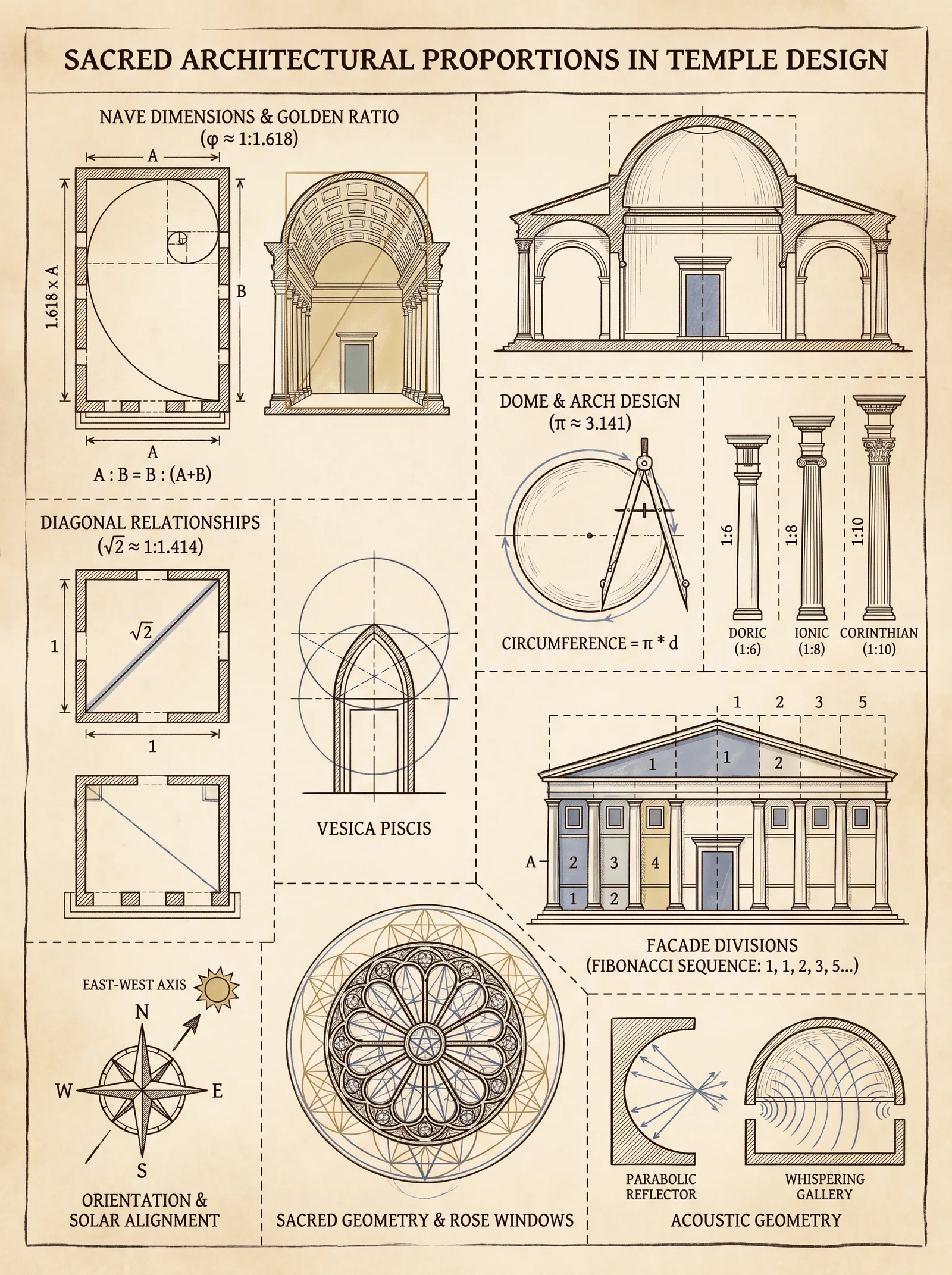
Preface
This chapter delivers the sacred knowledge of architectural proportions—the hidden language of geometry and ratio that transforms mere stone into sanctified space. The instructions herein are uncompromising and precise. The proportions and modular systems detailed are not aesthetic suggestions; they are divine constants that bind the physical with the metaphysical. Master these protocols to ensure your temple is a vessel worthy of the divine presence.
Section 1: The Foundation of Sacred Proportions
1.1 The Theoretical Framework
Sacred architecture is not measured in feet or cubits alone; it is measured in harmonies and resonances, transcribed through canonical ratios and symbolic geometry. These principles have been preserved through millennia from Egyptian, Greek, Indian, and Gothic traditions, converging on universal constants that evoke balance, sanctity, and the ineffable.
1.2 Canonical Ratios
The following ratios are the primary canonical proportions used in temple design. They govern the relationships between length, width, height, and ornamentation elements.
| Ratio Name | Numeric Value | Symbolic Meaning | Application Example |
|---|---|---|---|
| Golden Ratio (Φ) | 1 : 1.618 | Divine harmony, Life force | Facade length to height |
| Root 2 (√2) | 1 : 1.414 | Balance, Transition | Nave width to height |
| Root 3 (√3) | 1 : 1.732 | Spiritual ascent, Trinity | Column spacing |
| Root 5 (√5) | 1 : 2.236 | Expansion, Cosmic order | Temple length to width |
| 3:4:5 Triangle | 3 : 4 : 5 | Structural stability, Perfection | Base width, height, diagonal |
| Pi (π) in proportions | 1 : 3.1416 | Eternity, Circular motion | Dome diameter to height |
1.3 Modular Systems
Modularity is essential for replicability and sacred alignment. The module is the base measurement unit from which every dimension is derived.
- The Primary Module (M) is selected based on the temple’s intended scale and sanctity level.
- M** must be a whole number multiple of the human cubit** (approx. 52.5 cm), rounded to the nearest 0.5 cm for precision.
- Every major dimension (length, width, height) and ornamentation interval is an integer multiple or a canonical ratio multiple of M.
Section 2: Step-by-Step Protocol for Layout and Dimensioning
2.1 Defining the Primary Module (M)
- Measure the sacred cubit: Use a calibrated sacred rod or cord, length precisely 52.5 cm.
- Determine the temple scale: Identify the total intended length (L) based on ritual requirements or divine consultation.
- Calculate M: Divide L by a whole integer to find a base module that fits within canonical ratios and maximizes spatial harmony.
- Validate M: Ensure M is within 50 to 100 cm for structural feasibility, adjust if necessary.
2.2 Establishing the Temple Dimensions
- Set Length (L): Select L = M × n, where n is an integer chosen for ritual and functional requirements.
- Calculate Width (W): Apply the Golden Ratio: \[
W = \frac{L}{\Phi} \quad \text{or} \quad W = L \times 0.618
\] - Set Height (H): Use Root 2 proportion relative to Width: \[
H = W \times 1.414
\] - Determine Nave Height (Nh): Use Root 3 ratio with Width: \[
Nh = W \times 1.732
\] - Confirm Proportions: Verify that the dimensions satisfy the 3:4:5 triangle ratio where applicable, especially in the foundational floor plan.
2.3 Geometric Layout Construction
Tools Required: Compass, straightedge, calibrated measuring cord, chalk line.
Procedure:
- Draw the Base Rectangle:
- Using length L and width W, mark the rectangle on the ground.
- Construct the Golden Rectangle:
- From one corner of the rectangle, construct a square with side length W.
- Using the diagonal of this square as radius, swing an arc to locate the golden section on length L.
- Mark the Central Axis:
- Bisect the length and width to find the intersection point, which will serve as the temple’s spiritual axis.
- Draw the 3:4:5 Triangles:
- At each corner, construct right triangles with sides scaled according to the module M reflecting the 3:4:5 ratio for structural reference.
- Define Column Grid:
- Using Root 3 ratio, set column intervals at multiples of \( M \times 1.732 \).
- Establish Vertical Projections:
- Using plumb lines from the base, project vertical dimensions to establish wall height (H) and nave height (Nh).
Section 3: Symbolic Geometry and Ornamentation
3.1 Sacred Geometric Figures
The sacred geometry embedded in temple ornamentation communicates divine narratives. The following are essential geometries and their construction protocols:
| Geometric Figure | Symbolism | Construction Steps (Summary) |
|---|---|---|
| Vesica Piscis | Union, Duality | 1. Draw two circles of radius M intersecting at centers M apart. 2. The intersection forms the vesica piscis shape. |
| Flower of Life | Creation, Unity | 1. Construct a grid of overlapping circles arranged in hexagonal symmetry with radius M. 2. Repeat to desired scale. |
| Golden Spiral | Growth, Infinity | 1. Draw a series of quarter circles inside golden rectangles constructed from module M. 2. Connect arcs smoothly. |
| Pentagram | Protection, Spirit | 1. Construct a pentagon using Root 5 ratios from M. 2. Connect vertices in sequence to form the star. |
3.2 Protocol for Geometric Ornamentation
- Select Ornament Scale: Define ornament units as fractions or multiples of M (e.g., M/2, M×2).
- Draft Geometric Patterns: Using compass and straightedge, draft geometric figures on paper or digital medium at the defined scale.
- Transfer to Surface: Employ grid methods or proportional scaling (see Volume IV: Drafting and Scaling, Chapter V).
- Carve or Mold: Use chisels, templates, or molds to reproduce patterns in stone, wood, or metal, maintaining precision within ±1 mm.
- Verify Symmetry and Alignment: Use laser levels or plumb bobs to ensure ornamentation aligns with structural and symbolic axes.
Section 4: Historical Examples and Their Proportions
| Temple Name | Culture | Length (m) | Width (m) | Height (m) | Module (cm) | Ratios Employed |
|---|---|---|---|---|---|---|
| Parthenon | Ancient Greek | 69.5 | 30.9 | 13.7 | 69.5/21=33 | Golden Ratio, 3:4:5, Root 2 |
| Angkor Wat | Khmer Empire | 1900 | 1400 | 65 | 1400/40=35 | Root 3, Golden Ratio, Pi |
| Chartres Cathedral | Gothic France | 130 | 40 | 37 | 130/20=65 | Root 2, 3:4:5, Golden Ratio |
| Temple of Karnak | Egyptian | 250 | 100 | 32 | 100/25=40 | Root 5, Golden Ratio |
Section 5: Comprehensive Table of Canonical Proportions and Their Applications
| Element | Dimension Formula (based on M) | Ratio Used | Purpose/Notes |
|---|---|---|---|
| Temple Length (L) | \(L = M \times n\), \(n \in \mathbb{Z}^+\) | Modular base | Base dimension governing scale |
| Temple Width (W) | \(W = \frac{L}{\Phi}\) or \(W = L \times 0.618\) | Golden Ratio | Harmonizes length to width |
| Wall Height (H) | \(H = W \times \sqrt{2}\) (1.414) | Root 2 | Structural balance and visual harmony |
| Nave Height (Nh) | \(Nh = W \times \sqrt{3}\) (1.732) | Root 3 | Spiritual ascent and volume |
| Column Spacing | \(CS = M \times \sqrt{3}\) | Root 3 | Stability and rhythm |
| Dome Diameter | \(D = H \times \pi\) | Pi | Evokes eternity |
| Base Triangles | 3 : 4 : 5 multiples of M | Pythagorean triangle | Ensures structural integrity |
| Ornament Interval | \(O = M / 2\) or \(O = M / 3\) | Fractional Modular | Scale for decorative elements |
Section 6: Complete Step-by-Step Protocol for Designing a Sacred Temple Plan
Step 1: Select the Primary Module (M)
- Measure or select M based on desired temple length L and ritual scale.
Step 2: Calculate Dimensions
- Length: \(L = M \times n\), choose n for scale.
- Width: \(W = L \times 0.618\) (Golden Ratio).
- Wall Height: \(H = W \times 1.414\).
- Nave Height: \(Nh = W \times 1.732\).
Step 3: Layout Base Rectangle
- Mark on the ground with length L and width W.
Step 4: Construct Golden Rectangle and Central Axis
- Use compass and straightedge to locate golden section and spiritual center.
Step 5: Mark Structural Triangles and Column Grid
- Draw 3:4:5 triangles at corners.
- Set column spacing using Root 3 ratio multiples of M.
Step 6: Project Vertical Dimensions
- Using plumb lines, establish walls and nave heights.
Step 7: Draft Ornamentation Patterns
- Design ornaments based on modular fractions of M and sacred geometry figures.
Step 8: Transfer and Execute Construction
- Transfer layout and ornament patterns precisely onto site.
- Construct temple with strict adherence to proportions and symbolic geometries.
Conclusion
The sacred temple is a manifestation of divine order through proportion and geometry. Every length, every angle, every ornament must resonate with these eternal truths. This volume has delivered the complete technical foundation for designing, dimensioning, and ornamenting temples with canonical precision.
For structural engineering, material specifications, and ritual spatial arrangements, consult Volume IV: The Structural Codex, Volume V: Sacred Materials, and Volume VIII: Ritual Architecture, respectively.
End of Chapter III: Temple Proportions
May this knowledge be guarded, practiced with reverence, and passed only to those who seek to build not just structures, but sanctuaries of the divine.
<!-- SECTION 40 -->
The Complete Practitioner's Codex, Volume VII: The Builder's Testament
Chapter IV: Acoustic Design of Sacred Spaces
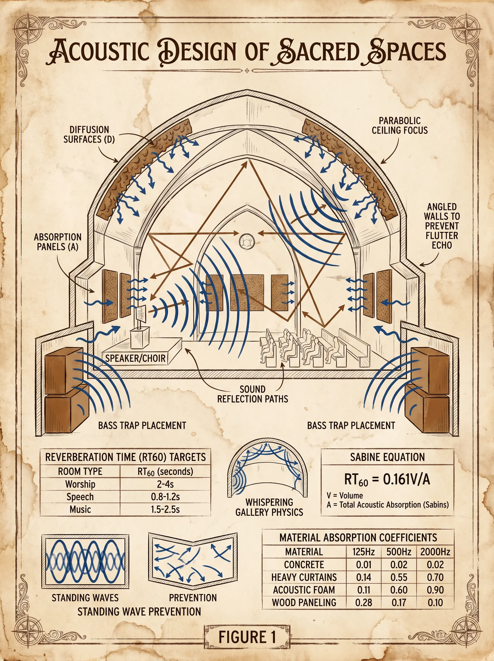
Principles of Acoustic Optimization: Resonance Chambers, Sound Reflection, and Absorption
Introduction: The Sacred Soundscape
In the creation of sanctified environments, acoustic design transcends mere comfort; it forms a conduit for divine resonance and spiritual clarity. The precise manipulation of sound waves within sacred chambers elevates ritual efficacy, purifies the auditory field, and harmonizes the human spirit with celestial frequencies. This chapter imparts the complete, unmitigated knowledge to master the acoustic domain within sacred architecture. The protocols herein are life-or-death in spiritual consequence and technical precision.
Section I: Fundamental Acoustic Principles in Sacred Architecture
1. Resonance Chambers: The Heart of Sacred Sound
Resonance chambers are architecturally crafted volumes designed to amplify and purify specific frequency bands aligned with sacred rites. These chambers must be dimensionally tuned, materialized with reverent precision, and spatially oriented to maximize harmonic convergence.
Key Variables:
- Chamber dimensions (length, width, height)
- Shape geometry (rectangular, elliptical, spherical)
- Material acoustic impedance and absorption coefficients
- Frequency targets aligned to sacred tonal scales (See Table 1)
2. Sound Reflection: Manipulation of Wave Paths
Reflection within sacred spaces can either augment or degrade spiritual acoustics. Controlled reflections create reverberation that enhances chanting and instrumental sounds, while errant reflections cause destructive interference and spiritual dissonance.
Reflection Principles:
- Angle of incidence equals angle of reflection (law of reflection)
- Use of angled surfaces (45°, 60°, 120°) to direct sound waves
- Avoidance of parallel reflective surfaces to prevent standing waves and flutter echoes
3. Sound Absorption: Elimination of Noise Pollution
Selective absorption removes unwanted frequencies, particularly mid-to-high frequency noise that disrupts ritual clarity. Absorptive materials must be precisely selected and positioned to balance reverberation time (RT60) within the sacred parameters.
Section II: Material Selection Protocol for Sacred Acoustic Optimization
Every material bears a unique absorption coefficient (α) — the fraction of incident sound energy absorbed rather than reflected. Sacred spaces require a harmonious blend of materials to sculpt the sonic environment.
Step-by-Step Material Selection Protocol
- Define frequency target range based on ritual requirements (typically 125 Hz to 4 kHz).
- Consult Table 2 (Material Absorption Coefficients) to identify materials with optimal α values at target frequencies.
- Calculate total surface area coverage where absorption is required (walls, ceilings, floors).
- Determine material thickness based on absorption performance (e.g., thicker fibrous materials absorb lower frequencies).
- Select materials with spiritual and physical durability—e.g., sacred woods, stone composites infused with mineral resins.
- Verify chemical inertness to avoid degradation in consecrated environments.
- Procure or fabricate materials using traditional techniques described in Volume III: The Material Codex, Chapter VI.
- Conduct in-situ material testing with calibrated sound level meters and frequency analyzers to confirm absorption coefficients.
Section III: Chamber Shaping and Dimensioning Protocols
The chamber shape dictates the modal distribution of sound waves and their harmonic interactions. The following stepwise protocol guides the shaping and dimensioning of resonance chambers for sacred spaces.
Step 1: Define the Primary Frequency Targets
Select the fundamental sacred frequencies from Table 1. These frequencies align with ancient tonal traditions and divine resonance principles.
Step 2: Calculate Chamber Dimensions Using the Formula for Resonant Modes
The fundamental frequencies in a rectangular chamber are calculated as:
\[ f_{n_x,n_y,n_z} = \frac{c}{2} \sqrt{\left(\frac{n_x}{L_x}\right)^2 + \left(\frac{n_y}{L_y}\right)^2 + \left(\frac{n_z}{L_z}\right)^2} \]
Where:
- \(f_{n_x,n_y,n_z}\) = resonant frequency for mode indices \(n_x, n_y, n_z\)
- \(c\) = speed of sound in air (343 m/s at 20°C)
- \(L_x, L_y, L_z\) = chamber length, width, height (meters)
- \(n_x, n_y, n_z\) = mode numbers (integers, starting at 1)
Step 3: Determine Chamber Geometry
- Rectangular chambers: Simple to calculate, ideal for modular construction.
- Elliptical chambers: Focus sound at foci, enhancing vocal clarity.
- Spherical chambers: Uniform modal distribution, complex to build but sacred in symbolism.
Step 4: Dimension Adjustment and Optimization
Adjust \(L_x, L_y, L_z\) to ensure:
- Fundamental modes align with sacred frequencies (Table 1)
- Avoid multiples or near-multiples causing modal overlaps (which generate dissonance)
- Target reverberation time (RT60) between 1.2 and 1.8 seconds for sacred clarity
Step 5: Finalize Chamber Shape with Surface Treatments
Apply acoustic diffusers and absorbers as dictated by reverberation measurements and reflection patterns.
Section IV: Tuning Protocol for Sacred Acoustic Chambers
Tuning is the iterative process of verifying and adjusting the acoustic properties of the chamber post-construction.
Step-by-Step Tuning Protocol
- Prepare equipment: calibrated omnidirectional microphone, frequency generator, real-time analyzer (RTA), and sound level meter.
- Generate test tones sweeping through target frequency range (125 Hz to 4 kHz).
- Measure resonance peaks and reverberation times at multiple chamber points.
- Identify problematic frequencies where resonance is excessive or deficient.
- Implement corrective measures:
- Add absorptive panels or diffusers at reflection points for excessive resonance.
- Remove or adjust surface materials for deficient resonance.
- Repeat measurements after each adjustment.
- Confirm final reverberation time (RT60) matches sacred standards.
- Document all tuning data and adjustment locations for future reference.
Section V: Data Tables for Sacred Acoustic Design
Table 1: Sacred Frequencies and Corresponding Spiritual Significance
| Frequency (Hz) | Wavelength (m) | Sacred Tone | Use Case in Rituals | Notes |
|---|---|---|---|---|
| 136.10 | 2.52 | C#3 (Om) | Meditation, grounding | Known as the "Om frequency" |
| 256.00 | 1.34 | C4 (Middle C) | Chanting base tone | Universal in musical tuning |
| 432.00 | 0.79 | A4 (Healing tone) | Healing ceremonies | Resonates with natural vibrations |
| 639.00 | 0.53 | F#5 (Connection) | Social harmony and community bonding | Enhances group rituals |
| 852.00 | 0.40 | G#5 (Awakening) | Spiritual awakening | Used in high-frequency chants |
Table 2: Material Absorption Coefficients (α) at Select Frequencies
| Material | 125 Hz | 250 Hz | 500 Hz | 1000 Hz | 2000 Hz | 4000 Hz | Thickness (cm) | Notes |
|---|---|---|---|---|---|---|---|---|
| Sacred Pine Wood | 0.10 | 0.15 | 0.20 | 0.25 | 0.30 | 0.35 | 5 | Natural, resonant wood |
| Mineral Resin Composite | 0.05 | 0.10 | 0.15 | 0.20 | 0.25 | 0.30 | 3 | Durable, chemically inert |
| Wool Felt Panels | 0.30 | 0.50 | 0.70 | 0.85 | 0.90 | 0.95 | 10 | High absorption, used on walls |
| Hemp Fiber Insulation | 0.40 | 0.60 | 0.75 | 0.80 | 0.85 | 0.90 | 15 | Biodegradable, eco-friendly |
| Quartz Sand Layer (packed) | 0.20 | 0.25 | 0.30 | 0.40 | 0.50 | 0.55 | 20 | Used in floors for bass absorption |
Table 3: Recommended Chamber Dimensions for Target Frequencies (Rectangular Chambers)
| Target Frequency (Hz) | Length (m) | Width (m) | Height (m) | Mode Numbers (nx, ny, nz) | Notes |
|---|---|---|---|---|---|
| 136.10 | 2.50 | 2.50 | 2.50 | (1,0,0) | Cube shape for fundamental "Om" tone |
| 256.00 | 1.34 | 1.34 | 1.34 | (1,0,0) | Compact chamber for clear Middle C tone |
| 432.00 | 0.79 | 1.58 | 1.58 | (1,2,0) | Rectangular with elongated width, height |
| 639.00 | 0.53 | 0.79 | 1.06 | (1,1,1) | Balanced mode distribution |
| 852.00 | 0.40 | 0.60 | 0.80 | (1,1,2) | Taller chamber for high-frequency clarity |
Section VI: Construction of a Resonance Chamber for the 136.10 Hz Om Frequency
Step 1: Select Location and Volume
- Choose a quiet, vibration-isolated zone.
- Construct a cube-shaped chamber measuring 2.5 m on each side (see Table 3).
Step 2: Material Preparation
- Use Sacred Pine Wood for walls, thickness 5 cm (Table 2).
- Apply a 10 cm layer of Wool Felt Panels on the interior surfaces for balanced absorption.
Step 3: Assembly
- Construct the wooden frame ensuring exact 2.5 m dimensions with ±0.5 cm tolerance.
- Install wool felt panels on all interior walls, ceiling, and floor using non-metallic fasteners to avoid resonance dampening.
- Seal joints with mineral resin composite for airtightness.
Step 4: Acoustic Testing and Tuning
- Generate a 136.10 Hz tone using a frequency generator placed at the chamber center.
- Measure resonance peaks with the omnidirectional microphone at multiple points.
- Add or remove wool felt panels in increments of 0.5 m² to adjust reverberation time between 1.2 and 1.5 seconds.
- Finalize tuning by adjusting surface angles with sacrificial wooden diffusers.
Section VII: Advanced Techniques: Shaping for Elliptical and Spherical Chambers
Elliptical Chambers (Focus on Vocal Clarity)
- Define ellipse with major axis \(a\) and minor axis \(b\) such that \(a/b = 1.5\) to 2.0 for optimal focus.
- Calculate foci positions using \(c = \sqrt{a^2 - b^2}\).
- Position altar or ritual focal point at one focus, performers or congregation at the other.
- Construct walls with curved laminated sacred wood panels, thickness 3-5 cm.
- Line interior with selectively placed absorptive panels at angles opposing foci to reduce echo.
Spherical Chambers (Uniform Modal Distribution)
- Determine radius \(r\) using the fundamental frequency formula for spherical resonators:
\[ f = \frac{c}{2 \pi r} \times \text{mode factor} \]
where the mode factor depends on spherical harmonics (consult advanced acoustic tables in Volume IX: The Harmonics Codex).
- Construct sphere using prefabricated mineral resin composite panels, thickness 5 cm.
- Install internal absorptive layers of hemp fiber insulation for low-frequency control.
- Use suspension systems to isolate the sphere from ground vibrations.
Section VIII: Summary and Final Notes
Mastery of sacred acoustic design demands integration of physics, material science, and sacred geometry. The protocols provided must be executed with absolute precision and reverence. Deviations result not only in architectural failure but spiritual dissonance imperiling all who enter the sacred chamber.
For complete water purification protocols supporting chamber humidification systems, see Volume VIII: The Water Codex, Chapter II. For advanced harmonic calculations, consult Volume IX: The Harmonics Codex, Chapter IV.
End of Chapter IV: Acoustic Design of Sacred Spaces The Builder's Testament continues with Chapter V: The Earthworks of Sanctity.
PLATES — Supplemental Gallery
Illustrations carried over from the original Codex Reader that belong to this volume as a whole. Added by this edition; the text above is complete without them.