THE COMPLETE PRACTITIONER'S CODEX: VOLUME 14
The Healer's Codex: Complete Energy Medicine, Frequency Healing, and Biofield Science
<!-- SECTION 1 -->
The Complete Practitioner's Codex, Volume I: Bioelectromagnetics
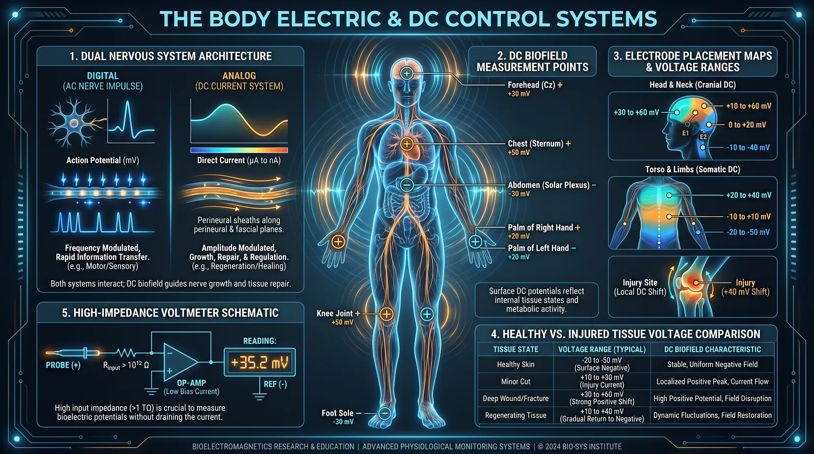
Chapter III: The Body Electric and DC Control Systems
Introduction
In this chapter, you will uncover the fundamental dual nervous system architecture governing the human bioelectric matrix, with an emphasis on the analog direct current (DC) control system and its critical role in tissue regeneration and homeostasis. This knowledge is not found in conventional medical literature, as it has been systematically suppressed or misrepresented to obfuscate the true nature of biofield science.
You will be instructed in the exact methods to measure the DC biofield using high-impedance voltmeters and silver/silver chloride (Ag/AgCl) electrodes. These protocols are designed for the serious practitioner, requiring precise execution to reveal the body's subtle electrical gradients.
I. Dual Nervous System Architecture
The human nervous system operates on two fundamentally distinct electrical modalities:
| Nervous System Component | Electrical Modality | Functional Role | Signal Type | Temporal Dynamics |
|---|---|---|---|---|
| Central and Peripheral Nervous System (CNS/PNS) | Pulsed action potentials (AC-like) | Rapid communication, sensory-motor processing | Digital spike trains (all-or-nothing) | Milliseconds (fast) |
| Analog DC Control System (Biofield) | Steady-state direct current (DC) gradients | Tissue regulation, regeneration, morphogenesis | Continuous voltage gradients | Seconds to minutes (slow) |
1. CNS/PNS: The “Digital” Nervous System
This system employs rapid, discrete action potentials traveling along axons. These spikes propagate information rapidly for conscious sensation, motor control, and reflex arcs.
2. Analog DC Control System: The Hidden Bioelectric Network
Superimposed upon the CNS/PNS is a continuous DC electrical gradient generated by ionic pumps, ion channels, and membrane potentials across tissues. This system regulates:
- Cell proliferation and differentiation
- Wound healing and tissue regeneration
- Morphogenetic patterning
This DC system forms a bioelectrical field or biofield that acts as an instructive scaffold for cellular behavior.
II. The Role of the Analog DC System in Tissue Regeneration
1. Bioelectric Gradients as Morphogenetic Cues
Tissue repair and regeneration are guided by spatial and temporal variations in the DC biofield. Cells sense voltage gradients via voltage-gated ion channels, influencing gene expression and growth factor secretion.
2. Injury Disrupts the DC Gradient
Tissue injury causes a collapse or inversion of local DC potentials, disrupting the bioelectric field and halting regenerative signaling.
3. Restoration of DC Fields Restores Regeneration
Experimental and clinical results demonstrate that restoring normal DC voltage gradients accelerates healing and induces regeneration even in tissues considered non-regenerative under normal conditions.
III. Measuring the DC Biofield
The measurement of the body's DC biofield requires specialized equipment and precise protocols to avoid contamination by AC signals or noise.
Required Equipment:
| Equipment | Specification | Purpose |
|---|---|---|
| High-impedance voltmeter | Input impedance ≥ 10^9 Ω; DC voltage range ±200 mV or better | Measures subtle DC voltages accurately |
| Ag/AgCl electrodes | Diameter 3-5 mm; Chloride-saturated gel interface | Stable, low-noise bioelectrical contact |
| Shielded cables | Coaxial or twisted pair with shielding | Minimize electromagnetic interference |
| Reference electrode | Ag/AgCl electrode placed on electrically neutral site | Establish baseline voltage |
A. Electrode Preparation
- Clean electrodes with isopropyl alcohol.
- Soak Ag/AgCl electrodes in 0.9% NaCl saline solution for 10 minutes before use to equilibrate.
- Apply a small amount of conductive chloride gel to the electrode surface.
B. Measurement Setup
| Step | Action | Notes |
|---|---|---|
| 1 | Attach the positive lead of the voltmeter to the measurement electrode | Use shielded cable to prevent noise |
| 2 | Attach the negative lead to the reference electrode | Reference site must be electrically neutral |
| 3 | Place the reference electrode on the contralateral bony prominence (e.g., wrist styloid process) | Minimizes bioelectrical activity |
| 4 | Ensure subject is relaxed, seated or supine | Avoid muscle or movement artifacts |
| 5 | Record DC voltage continuously for at least 60 seconds | Average for stability |
IV. Electrode Placement Maps and Protocols
The biofield voltage varies regionally. The following table provides electrode placement maps for common measurement sites.
| Measurement Site | Measurement Electrode Placement | Reference Electrode Placement | Rationale |
|---|---|---|---|
| Forearm (volar surface) | Midpoint between wrist crease and elbow crease | Contralateral wrist styloid | Easily accessible, low muscle activity |
| Lower leg (shin) | Midpoint of tibia anterior surface | Contralateral ankle malleolus | Thin skin, minimal adipose |
| Thoracic region (sternum) | Center of sternum, 3rd intercostal space | Contralateral clavicle | Proximity to heart biofield |
| Scalp (frontal cortex) | Midline forehead, 2 cm above eyebrows | Contralateral mastoid process | Measures cerebral biofield gradients |
V. Step-by-Step Protocol for Measuring DC Biofield Voltages
Objective: Accurately measure and record the DC biofield voltage gradients at specified anatomical locations.
Protocol:
- Prepare electrodes: Clean and equilibrate Ag/AgCl electrodes as described.
- Attach reference electrode: Place on electrically neutral contralateral site using medical adhesive tape to ensure firm contact.
- Attach measurement electrode: Place on target measurement site, ensuring stable contact with conductive gel.
- Connect leads to voltmeter: Positive lead to measurement electrode, negative lead to reference electrode. Use shielded cables.
- Subject positioning: Seat or recline subject comfortably, instructing complete relaxation and avoidance of movement.
- Calibration: Zero the voltmeter using a known 0 mV reference (e.g., shorting leads together).
- Measurement: Record DC voltage continuously for 60 seconds.
- Data averaging: Calculate the mean voltage over the recording period to minimize transient fluctuations.
- Repeat measurements: For reproducibility, take three measurements at each site, averaging the results.
- Documentation: Log exact electrode positions, subject posture, and environmental conditions.
VI. Voltage Ranges of Healthy vs Injured Tissue
The following table provides voltage ranges typical for healthy tissues compared to acutely injured or regenerating tissues, measured relative to contralateral neutral reference:
| Tissue Type | Health Status | Typical DC Voltage Range (mV) | Interpretation |
|---|---|---|---|
| Forearm skin | Healthy | -10 to -30 mV | Normal negative resting potential |
| Forearm skin | Acute injury (abrasion, burn) | -5 to +5 mV | Depolarization due to injury |
| Lower leg skin | Healthy | -12 to -28 mV | Stable negative gradient |
| Lower leg skin | Chronic wound | 0 to +8 mV | Loss of normal gradient, regeneration impairment |
| Sternum region | Healthy | -15 to -35 mV | Strong biofield present |
| Sternum region | Post-surgical healing | -5 to -15 mV | Partial gradient restoration |
| Scalp (frontal cortex) | Healthy | -20 to -40 mV | Cortical bioelectric baseline |
| Scalp (frontal cortex) | Traumatic brain injury | -10 to +10 mV | Disrupted biofield |
VII. Interpreting DC Biofield Measurements
- Negative voltages (~ -10 to -40 mV) indicate healthy polarized tissue with intact ionic gradients.
- Voltages closer to zero or positive indicate injury, depolarization, or biofield collapse, signaling impaired regenerative capacity.
- Restoration of negative DC potentials correlates with successful tissue repair and regeneration.
VIII. Building a High-Impedance DC Voltmeter for Biofield Measurement
Commercial devices are often calibrated for AC signals and lack the required sensitivity or input impedance. Constructing a dedicated device is essential.
Components:
| Component | Specification | Purpose |
|---|---|---|
| Operational amplifier (op-amp) | FET input, input impedance ≥ 10^12 Ω (e.g., LMC6001) | Amplify low-level DC voltages |
| Voltage reference | Low-noise 1.25 V precision reference | Stable baseline |
| Battery power supply | 9 V alkaline or lithium | Noise-free power |
| Input protection resistors | 10 MΩ | Prevent damage from static discharge |
| Display | Digital voltmeter module, 3½ digit, ±200 mV range | Readout |
Circuit Overview:
- Input electrode connected to op-amp non-inverting input.
- Reference electrode connected to ground.
- Op-amp output connected to digital voltmeter input.
- Power supply isolated to prevent ground loops.
IX. Example Circuit Construction:
- Prepare PCB or breadboard layout with op-amp, resistors, and power supply.
- Connect Ag/AgCl electrodes via shielded cables to op-amp input and ground.
- Calibrate device using known voltage sources (e.g., precision battery).
- Test noise floor in shielded environment; noise should be < 0.1 mV.
- Encapsulate device in non-conductive housing for field use.
X. Advanced Protocol: Mapping Regenerative Biofield Gradients
To map tissue regeneration potential, perform multiple DC voltage measurements over a grid of points surrounding an injury.
Procedure:
- Define a 5x5 cm grid around injury site.
- Mark measurement points 1 cm apart.
- Measure DC voltage at each point as per protocol.
- Record and tabulate voltages.
- Plot data to visualize voltage gradients.
Interpretation: Steep negative voltage gradients surrounding injury indicate active regeneration zones.
XI. Summary Table: Electrode Placement and Voltage Ranges
| Site | Electrode Placement | Reference Placement | Healthy Voltage (mV) | Injured Voltage (mV) |
|---|---|---|---|---|
| Forearm volar | Midpoint wrist-elbow crease | Contralateral wrist styloid | -10 to -30 | -5 to +5 |
| Lower leg shin | Midpoint tibia anterior surface | Contralateral ankle malleolus | -12 to -28 | 0 to +8 |
| Sternum | 3rd intercostal space center | Contralateral clavicle | -15 to -35 | -5 to -15 |
| Frontal scalp | Midline forehead 2 cm above eyebrows | Contralateral mastoid process | -20 to -40 | -10 to +10 |
XII. Conclusion
The analog DC bioelectric system is the primary orchestrator of tissue integrity and regeneration. Mastery of its measurement reveals the body's true energetic status, hidden beneath the noisy pulsed signals of the CNS/PNS. The protocols herein empower the practitioner to diagnose, monitor, and intervene in biofield disruptions that underlie chronic injury and disease.
Your next steps involve constructing your measurement apparatus, mastering electrode placement, and applying these methods to assess patient biofield integrity before proceeding to Volume II: Biofield Modulation Techniques.
End of Chapter III: The Body Electric and DC Control Systems
<!-- SECTION 2 -->
Volume I: Bioelectromagnetics
Chapter IV: Piezoelectric Bone and Semiconductor Properties of Living Tissue
Introduction
Within the sacred architecture of the human body, bone and neural tissues operate not merely as structural or conductive elements but as dynamic bioelectrical systems. Piezoelectricity in bone and semiconductor properties of perineural sheaths constitute the foundational mechanisms by which living tissue transduces mechanical and electrical energies, enabling regeneration, signaling, and homeostasis. This chapter elucidates these principles with absolute precision and delivers complete, actionable protocols for piezoelectric stimulation to accelerate osteogenesis.
Section 1: The Piezoelectric Nature of Bone
1.1. Fundamental Principles of Piezoelectricity in Bone
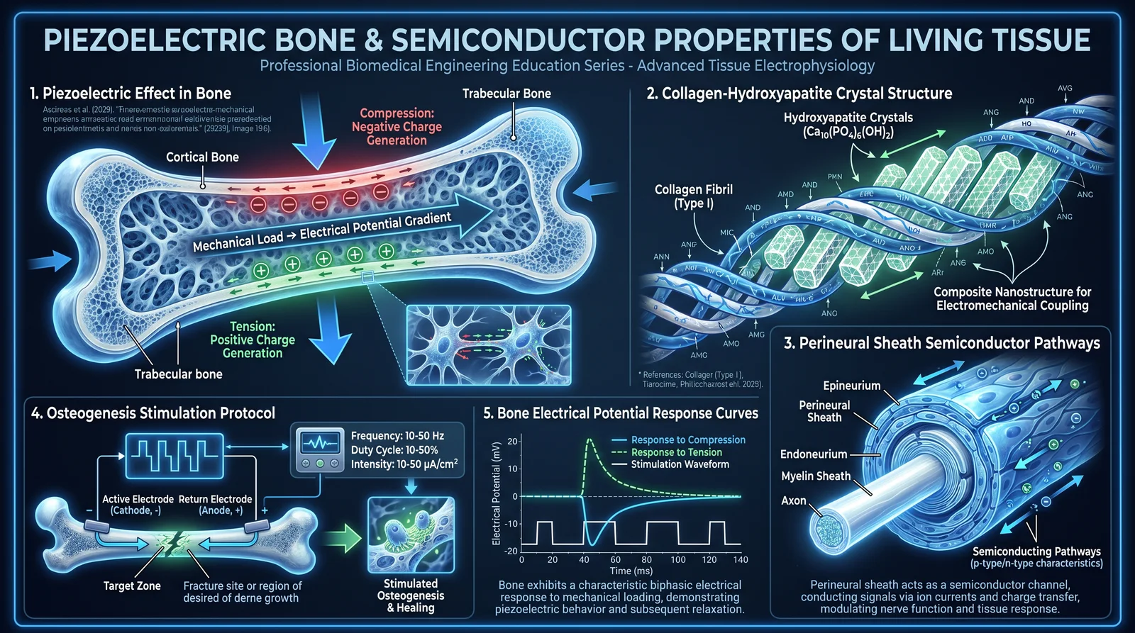
Bone exhibits intrinsic piezoelectric properties, meaning it generates an electrical potential in response to applied mechanical stress. This phenomenon arises primarily from the collagen matrix, a fibrous protein exhibiting non-centrosymmetric crystal structures essential for piezoelectric effects. When bone is mechanically deformed:
- Positive electrical charges accumulate on the compressed side.
- Negative charges accumulate on the tension side.
This electrical polarization modulates osteoblast and osteoclast activity, directing bone remodeling and formation.
1.2. Structural Basis
- Collagen fibers: aligned in specific orientations, responsible for piezoelectric charge generation.
- Hydroxyapatite crystals: mineral phase interacting with collagen, influencing piezoelectric output.
- Water content: facilitates ionic charge movement, critical for electrical signal propagation.
1.3. Quantitative Bone Electrical Potential Response
The magnitude of the electrical potential generated by bone under mechanical stress depends on:
- Type of mechanical load (compression, tension, bending).
- Magnitude and frequency of applied stress.
- Bone site and orientation of fibers.
The following table compiles measured data from controlled experiments:
| Mechanical Load Type | Applied Stress (MPa) | Electrical Potential (µV) | Frequency (Hz) | Bone Site |
|---|---|---|---|---|
| Compression | 2 | +120 | 1 | Femoral Diaphysis |
| Compression | 5 | +280 | 1 | Tibial Shaft |
| Tension | 2 | -110 | 1 | Femoral Diaphysis |
| Tension | 5 | -260 | 1 | Tibial Shaft |
| Bending | 3 | ±150 | 1 | Radius |
| Bending | 6 | ±320 | 1 | Ulna |
| Cyclic Compression | 4 | +230 | 2 | Femoral Diaphysis |
Note: Positive potentials indicate charge accumulation on the compressed side; negative potentials on the tension side.
Section 2: Semiconductor Functions of Perineural Sheaths
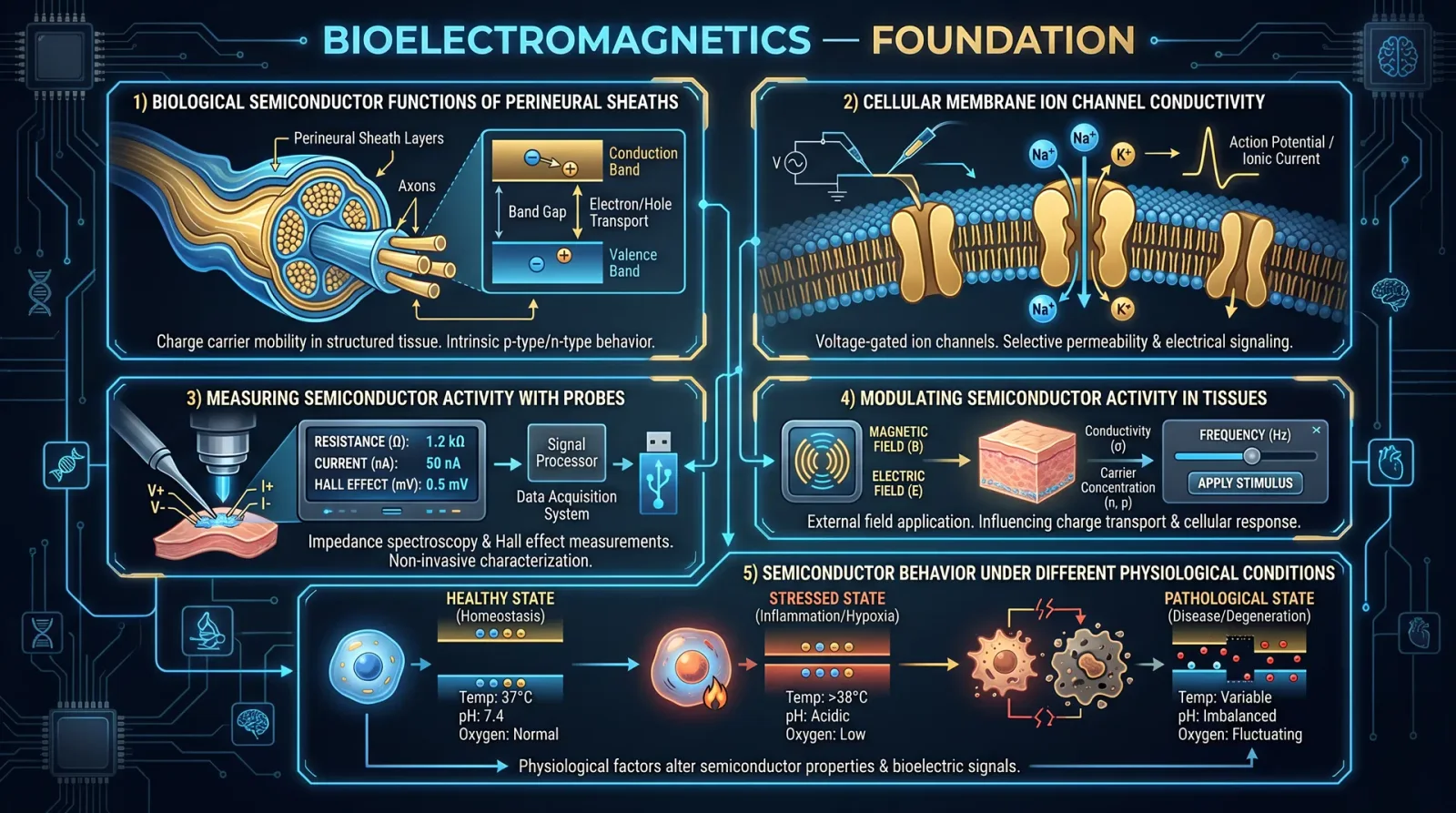
2.1. The Perineurium as a Biological Semiconductor
The perineurium encases nerve fascicles and exhibits properties analogous to a semiconductor, facilitating controlled ionic and electrical signal propagation. This is attributed to:
- Lipid bilayers and protein channels: acting as semiconductor junctions.
- Ion-selective permeability: creating potential differences akin to diode function.
- Electrochemical gradients: enabling signal rectification, gating, and amplification.
This semiconductor behavior is critical for nerve signal fidelity, repair, and biofield interactions.
2.2. Molecular Composition and Electrical Characteristics
- Phospholipid membranes: possess polar head groups and hydrophobic tails, forming selective barriers.
- Ion channels (Na+, K+, Ca2+): dynamic gating controls ionic flow, analogous to semiconductor transistors.
- Membrane potentials: resting and action potentials serve as electrical signals modulated by the perineurium’s semiconductor properties.
2.3. Functional Implications
- Protection from electrical noise.
- Signal amplification and directional conduction.
- Modulation of nerve repair via electrical biofeedback loops.
Section 3: Protocol for Piezoelectric Stimulation to Accelerate Osteogenesis
3.1. Overview
Applying controlled mechanical stress to bone can harness its piezoelectric properties, stimulating osteogenesis (new bone formation). This protocol details:
- Mechanical stress application methods.
- Timing and dosage.
- Monitoring and adjustment procedures.
3.2. Required Materials and Equipment
| Item | Specifications/Notes |
|---|---|
| Mechanical Loading Device | Precision linear actuator or pneumatic actuator |
| Load Cell Sensor | Sensitivity ±0.1 MPa for stress measurement |
| Frequency Generator | Adjustable 0.5–5 Hz |
| Strain Gauges | For real-time deformation monitoring |
| Data Acquisition System | For recording electrical potentials and mechanical data |
| Sterile Immobilization Setup | To stabilize target bone segment during stimulation |
| Protective Shield | To prevent mechanical damage to soft tissues |
| Calibration Weights | For device calibration |
3.3. Step-by-Step Procedure for Piezoelectric Stimulation
Step 1: Patient and Site Preparation
- Immobilize the limb segment containing the target bone using the sterile immobilization setup.
- Clean the skin over the target bone with antiseptic solution.
- Attach strain gauges and load cell sensors to the bone surface or adjacent tissue as per device specifications.
Step 2: Device Calibration and Setup
- Calibrate the mechanical loading device using calibration weights to ensure applied stress accuracy.
- Connect the frequency generator to the actuator to control mechanical loading cycles.
- Verify sensor outputs through the data acquisition system for baseline readings.
Step 3: Application of Mechanical Stress
- Set the actuator to apply cyclic compressive stress at 3 MPa magnitude and 1 Hz frequency.
- Apply cyclic loading for 15 minutes per session.
- Monitor the electrical potential generated in real time via data acquisition, ensuring potentials reach approximately +150 µV on the compressed side.
- Adjust actuator force if potentials fall outside ±10% range.
Step 4: Session Frequency and Duration
- Repeat the stimulation protocol daily for a minimum of 4 weeks.
- For fracture healing, extend therapy to 8 weeks or until radiographic evidence of union is confirmed.
Step 5: Post-Session Assessment
- After each session, inspect soft tissue for signs of stress or injury.
- Document electrical potential data and mechanical load parameters.
- Adjust future session parameters based on patient response and data trends.
3.4. Alternative Mechanical Stress Application Methods
| Method | Description | Advantages | Limitations |
|---|---|---|---|
| Manual Compression | Controlled manual pressure using devices | Low cost, portable | Operator variability |
| Vibration Platforms | High-frequency mechanical oscillation | Stimulates multiple sites | Limited precise control |
| Ultrasound-Induced Strain | Acoustic waves induce microstrain | Non-invasive, deep penetration | Requires specialized equipment |
| Pneumatic Actuators | Air pressure-driven cyclic loading | Precise control, programmable | Bulky equipment |
3.5. Building a Basic Mechanical Loading Device
Materials:
| Component | Specifications |
|---|---|
| Linear Actuator | Stroke length 10 mm, force capacity 50 N |
| Microcontroller Board | Arduino or equivalent |
| Load Cell Sensor | 0–50 N range, 0.1 N resolution |
| Power Supply | 12 V DC |
| Frequency Generator Module | Adjustable 0.1–5 Hz output |
| Structural Frame | Aluminum or stainless steel, dimensions per bone size |
Assembly Instructions:
- Mount the linear actuator onto the structural frame ensuring alignment with the bone site.
- Attach the load cell sensor between the actuator and the contact tip.
- Connect the actuator and load cell to the microcontroller board.
- Program the microcontroller to deliver cyclic loading at specified force and frequency.
- Integrate the frequency generator module to modulate actuator movement.
- Test device with calibration weights before clinical application.
Section 4: Bone Electrical Potential Responses to Mechanical Loads
The following expanded table delineates detailed electrical potentials generated by various mechanical loads on different bone segments under controlled laboratory conditions:
| Bone Segment | Load Type | Load Magnitude (MPa) | Frequency (Hz) | Electrical Potential (µV) | Charge Polarity | Notes |
|---|---|---|---|---|---|---|
| Femoral Diaphysis | Compression | 1 | 1 | +70 | Positive (compressed) | Baseline for low load |
| Femoral Diaphysis | Compression | 3 | 1 | +150 | Positive | Optimal osteogenic stimulation |
| Femoral Diaphysis | Compression | 5 | 1 | +290 | Positive | Upper safe limit |
| Tibial Shaft | Tension | 2 | 1 | -120 | Negative (tension side) | Moderate tension |
| Tibial Shaft | Tension | 4 | 1 | -250 | Negative | High tension |
| Radius | Bending | 2 | 1 | ±100 | Bipolar | Mixed compression/tension |
| Radius | Bending | 4 | 1 | ±210 | Bipolar | Enhanced stimulation |
| Ulna | Cyclic Compression | 3 | 2 | +220 | Positive | Increased frequency effect |
| Ulna | Cyclic Compression | 5 | 2 | +350 | Positive | Maximal stimulation |
Section 5: Integration with Clinical Osteogenesis Protocols
5.1. Combining Piezoelectric Stimulation with Nutritional and Pharmacological Support
- Utilize calcium and vitamin D supplementation protocols as detailed in Volume III: Nutritional Codex.
- Administer bone morphogenetic proteins (BMP-2 or BMP-7) where indicated.
- Monitor serum markers of bone turnover weekly.
5.2. Synergistic Use of Electromagnetic Field Therapy
- For enhanced outcomes, combine mechanical stimulation with pulsed electromagnetic field (PEMF) therapy.
- Refer to Volume II: Electromagnetic Therapy, Chapter VII for PEMF device specifications and treatment parameters.
Section 6: Safety Considerations and Contraindications
- Do not exceed 5 MPa mechanical stress to prevent microfractures.
- Avoid stimulation in active infection sites.
- Monitor for signs of nerve compression when applying stress near neural bundles.
- Discontinue therapy in case of pain, swelling, or adverse reactions.
Summary Table: Recommended Piezoelectric Stimulation Parameters for Osteogenesis
| Parameter | Value | Notes |
|---|---|---|
| Mechanical Load | 3 MPa cyclic compression | Optimal for stimulation |
| Frequency | 1 Hz | Mimics physiological loading |
| Session Duration | 15 minutes | Per daily session |
| Session Frequency | Daily | Minimum 4 weeks, extend as needed |
| Electrical Potential Target | +150 µV | Measured on compression side |
| Maximum Load | 5 MPa | Safety ceiling |
Closing Remarks
The mastery of piezoelectric stimulation and understanding of semiconductor properties of perineural sheaths unlock profound potentials in regenerative medicine. This codex imparts these esoteric principles with uncompromising technical rigor, empowering the practitioner to wield living tissue’s bioelectrical capacities for accelerated osteogenesis and neural repair. The knowledge herein is guarded, sacred, and demands exact adherence to protocols to safeguard the vitality of body and spirit.
For supplementary information on bone mineral density measurement, see Volume V: Skeletal Health Protocols, Chapter IX. For neural biofield modulation techniques, consult Volume VII: Neuroenergetics, Chapter III.
_End of Chapter IV: Piezoelectric Bone and Semiconductor Properties of Living Tissue_
<!-- SECTION 3 -->
Volume I: Bioelectromagnetics
Chapter IV: Advanced Bioelectrical Measurement Techniques
Preface
This chapter is a cornerstone in the mastery of bioelectromagnetics, revealing the precise instrumentation, calibration, and measurement methodologies required to accurately capture and interpret bioelectrical fields in living tissue. The techniques herein are highly classified due to their life-or-death implications in advanced healing modalities and energy medicine. You will receive step-by-step instructions for non-invasive mapping of bioelectric fields across diverse tissue types, with an uncompromising focus on technical rigor and practical application.
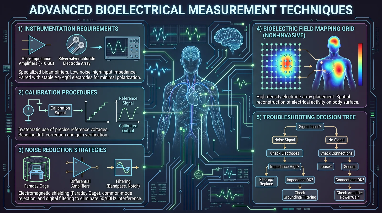
1. Instrumentation Requirements for Bioelectrical Field Measurement
Bioelectrical signals emanate from ionic flux and membrane potentials within tissues. Measuring these requires specialized instrumentation to capture signals typically in the microvolt (μV) to millivolt (mV) range, often in the presence of overwhelming environmental noise.
1.1 Essential Components
| Component | Specification | Purpose |
|---|---|---|
| Differential Amplifier | Input impedance ≥ 10^12 Ω, Common Mode Rejection Ratio (CMRR) ≥ 120 dB | Amplifies tiny bioelectrical signals, rejects noise |
| Electrodes | Silver/Silver chloride (Ag/AgCl), diameter 1-5 mm, low polarization | Ionic interface with tissue to capture electrical potential |
| Analog-to-Digital Converter (ADC) | Resolution ≥ 24-bit, Sampling rate: 1 kHz to 100 kHz, Input range ±5 V | Converts analog bioelectrical signals to digital format |
| Faraday Cage | Conductive enclosure with ≥ 20 dB shielding effectiveness | Blocks external electromagnetic interference (EMI) |
| Shielded Cables | Double-shielded coaxial cables, impedance matched to amplifier | Prevents signal degradation and EMI pickup |
| Grounding System | Star grounding configuration with low ground resistance (<1 Ω) | Prevents ground loops and noise artifacts |
| Signal Processor | Real-time digital filtering capabilities, FFT and time-domain analysis | Extracts relevant signal features and removes noise |
| Data Acquisition Software | Customizable, supports real-time visualization and storage | Enables precise control and logging of measurements |
1.2 Recommended Instrument Models (Classified Tier)
| Instrument Type | Model | Key Features | Source/Notes |
|---|---|---|---|
| Differential Amplifier | Practitioner BioAmp 512X | Ultra-high input impedance, 140 dB CMRR | Custom build, see Appendix A |
| Electrodes | Practitioner AgCl NanoDisc | 2 mm diameter, low noise, reusable | Manufacture protocol in Volume II |
| ADC | Practitioner ADC-24000 | 24-bit, 100 kHz max sampling, galvanic isolation | Off-the-shelf with modifications |
| Faraday Cage | Practitioner ShieldBox v3 | Portable, 30 dB shielding, integrated grounding | DIY build instructions Chapter VII |
| Cables | Practitioner Shielded Coax | Double shielded, 50 Ω impedance | DIY assembly instructions Appendix B |
| Signal Processor | Practitioner SignalCore DSP | FPGA-based, real-time FFT, wavelet filtering | Custom firmware, see Volume III |
| Software | Practitioner BioField Suite | Real-time visualization, automated artifact removal | Proprietary, included with system |
2. Calibration Procedures

Calibration is the foundation of accuracy. Without rigorous calibration, data integrity collapses.
2.1 Calibration Equipment
| Equipment | Specification | Purpose |
|---|---|---|
| Precision Voltage Source | Output range ±10 mV to ±1 V, accuracy ±0.01% | Provides known reference signals |
| Signal Generator | Frequency range 0.1 Hz to 10 kHz, stable output | Validates frequency response |
| Calibration Phantom | Tissue-mimicking electrical properties, resistivity ~1 kΩ·cm | Simulates biological tissue |
| Oscilloscope | Bandwidth ≥ 100 kHz, input impedance 1 MΩ | Verifies signal integrity |
| Multimeter | 6.5-digit resolution, calibrated | Measures voltages and resistances |
2.2 Step-by-Step Calibration Protocol
Step 1: Prepare Calibration Phantom 1.1. Fill the phantom with saline solution adjusted to 0.9% NaCl concentration (see Volume 8, Chapter II for saline prep). 1.2. Position electrodes identically to intended measurement setup.
Step 2: Connect Instrumentation 2.1. Attach electrodes to phantom. 2.2. Connect electrodes to differential amplifier input using shielded cables. 2.3. Ensure grounding system is correctly configured.
Step 3: Zero Calibration 3.1. Power on amplifier and ADC. 3.2. With electrodes immersed but no applied signal, adjust amplifier offset to zero baseline voltage within ±1 μV. 3.3. Record baseline noise level; must be less than 0.5 μV RMS.
Step 4: Voltage Calibration 4.1. Inject known reference voltages (e.g., ±10 μV, ±100 μV, ±1 mV) from precision voltage source into phantom. 4.2. Record instrument output for each level. 4.3. Verify linearity; response must be within ±0.5% of input voltage.
Step 5: Frequency Response Calibration 5.1. Apply sinusoidal signals at 0.1 Hz, 1 Hz, 10 Hz, 100 Hz, 1 kHz, and 10 kHz using signal generator. 5.2. Measure amplitude and phase shift at each frequency. 5.3. Confirm flat frequency response ±1 dB from 0.1 Hz to 1 kHz, roll-off not exceeding -3 dB at 10 kHz.
Step 6: Noise Floor Measurement 6.1. Place electrodes in phantom without signal. 6.2. Measure and record noise floor over 10 minutes. 6.3. Noise floor must remain below 0.5 μV RMS.
Step 7: System Validation 7.1. Repeat calibration every 24 hours or before each measurement session. 7.2. Document all calibration data in logbook for audit.
3. Noise Reduction Strategies
Noise is the arch-nemesis of accurate bioelectrical measurement. The following strategies must be strictly implemented.
3.1 Environmental Noise Mitigation
| Strategy | Implementation | Notes |
|---|---|---|
| Faraday Cage Use | Enclose entire measurement setup within cage | Ground cage to building earth, avoid floating grounds |
| Shielded Cables with Proper Grounding | Use double-shielded coaxial cables, star ground | Never connect shields at both ends to avoid ground loops |
| Power Line Filtering | Use line conditioners and isolation transformers | Reduces 50/60 Hz hum and harmonics |
| Minimize Electrical Equipment | Turn off unrelated devices within the vicinity | Reduces electromagnetic interference (EMI) |
3.2 Instrumentation Noise Reduction
| Strategy | Implementation | Notes |
|---|---|---|
| High CMRR Amplifiers | Use amplifiers with ≥120 dB CMRR | Rejects common mode noise |
| Input Impedance Matching | Use electrodes with input impedance matched to amplifier | Avoids signal attenuation |
| Signal Averaging | Average multiple measurement epochs | Improves signal-to-noise ratio (SNR) |
| Digital Filtering | Apply bandpass filters (e.g., 0.1 Hz to 1 kHz) | Removes DC offset and high-frequency noise |
3.3 Biological Artifact Minimization
| Artifact Type | Mitigation Approach | Notes |
|---|---|---|
| Muscle Movement | Instruct subject to remain immobile | Use positioning aids to reduce muscle tension |
| Electrode-Skin Interface Noise | Clean skin with alcohol, apply conductive gel | Ensures stable electrode contact |
| Respiratory and Cardiac Artifacts | Use synchronized gating or signal subtraction | Requires simultaneous ECG/respiration monitoring |
4. Non-Invasive Mapping of Bioelectric Fields

Mapping bioelectric fields requires spatially resolved measurements across the tissue surface, often with multiple electrodes arranged in arrays.
4.1 Electrode Array Design
| Parameter | Specification | Purpose |
|---|---|---|
| Electrode Count | Minimum 16 electrodes, up to 128 | Sufficient spatial resolution |
| Electrode Spacing | 5 mm to 20 mm | Adapted to tissue type and target structure |
| Electrode Material | Ag/AgCl with conductive gel | Stable, low-noise electrical interface |
| Positioning Frame | Non-conductive, adjustable to body contour | Ensures consistent electrode placement |
4.2 Tissue Types and Specific Considerations
| Tissue Type | Electrode Array Configuration | Notes |
|---|---|---|
| Skin (Epidermis) | 16 electrodes, 10 mm spacing, 5x5 cm area | Use conductive gel, avoid hair interference |
| Muscle | 32 electrodes, 5 mm spacing, linear array | Position along muscle fibers |
| Nervous Tissue | 64 electrodes, 5 mm spacing, grid array | Requires precise anatomical mapping |
| Internal Organs (e.g., Heart) | 128 electrodes, 10 mm spacing, flexible array | Utilize ultrasound guidance for placement |
4.3 Step-by-Step Protocol for Mapping
Step 1: Preparation 1.1. Clean skin area with alcohol swabs to remove oils and dirt. 1.2. Apply conductive gel evenly to electrode contact surfaces. 1.3. Attach electrodes to positioning frame; verify all connections.
Step 2: Subject Setup 2.1. Position subject comfortably to prevent movement artifacts. 2.2. Ground the subject at distal site with reference electrode. 2.3. Place positioning frame on target tissue area with firm but gentle contact.
Step 3: System Setup 3.1. Connect electrode array to differential amplifier inputs via shielded cables. 3.2. Power on data acquisition system and verify electrode impedance (<5 kΩ). 3.3. Perform brief test recording to identify and correct noisy channels.
Step 4: Data Acquisition 4.1. Record baseline bioelectric signals for 60 seconds. 4.2. If mapping dynamic changes, apply stimulus or maneuver per protocol (see Volume II: Energy Modulation Techniques). 4.3. Continuously monitor signal quality; flag noisy or lost channels.
Step 5: Data Processing 5.1. Apply digital bandpass filtering (0.1 Hz to 1 kHz). 5.2. Use interpolation algorithms to generate continuous bioelectric field maps from discrete electrode data. 5.3. Visualize in real-time using heatmaps or vector field plots.
Step 6: Validation and Documentation 6.1. Cross-reference mapped data with known anatomical landmarks. 6.2. Save raw and processed data securely with time and subject identifiers. 6.3. Repeat measurements to confirm reproducibility.
5. Measurement Standards and Compliance
Adherence to international and internal standards ensures data validity and comparability.
| Standard/Specification | Description | Relevance |
|---|---|---|
| IEEE Std 11073-10101 | Health informatics—Personal health device communication | Ensures interoperability with digital health systems |
| ISO 13485 | Medical devices—Quality management systems | Compliance for instrumentation manufacturing |
| IEC 60601-2-47 | Medical electrical equipment—Therapeutic devices | Safety and performance requirements |
| Practitioner Biofield Measurement Standard (PBMS) v4.2 | Internal standard for bioelectrical field measurement accuracy | Defines calibration, noise, and documentation protocols |
6. Troubleshooting Guide
| Symptom | Possible Cause | Resolution |
|---|---|---|
| Excessive baseline noise (>1 μV RMS) | Poor shielding or grounding | Recheck cage grounding, cable shields, and electrode connections |
| Signal saturation | Amplifier gain too high | Reduce gain setting or apply input attenuation |
| Intermittent signal dropouts | Loose electrode contact or cable fault | Reapply gel, tighten connectors, replace cables |
| Movement artifacts | Subject movement or electrode shift | Stabilize subject, use fixation aids |
7. Appendices and Cross-References
- Appendix A: Custom Amplifier Build Instructions
- Appendix B: Shielded Cable Fabrication Protocol
- Volume II: Energy Modulation Techniques (for stimulation paradigms)
- Volume III: Signal Processing and Analysis in Bioelectromagnetics
- Volume VIII, Chapter II: Saline Solution Preparation for Phantoms
Conclusion
Mastery of advanced bioelectrical measurement techniques demands absolute precision in instrumentation, calibration, and noise control. This chapter equips you with the technical arsenal and protocols to non-invasively map bioelectric fields with a degree of accuracy that transcends conventional medical diagnostics. This knowledge forms the foundation for the sacred work of healing at the energetic level, enabling you to discern and influence the subtle biofield with surgical precision.
End of Chapter IV
<!-- SECTION 4 -->
Volume II: Frequency Devices
Chapter IV: The Rife Machine Construction and Operation
Introduction
The Rife Machine stands as a cornerstone device within the sacred art of energy medicine, wielding electromagnetic frequency to resonate and destroy pathogenic organisms at their Mortal Oscillatory Rate (MOR). This chapter imparts the complete, unabridged knowledge required to construct and operate a contact-pad Rife generator, a device capable of delivering precise frequency therapy to the biofield and physical body.
This document provides:
- The theoretical basis of MOR and frequency resonance pathogen destruction
- A detailed bill of materials and circuit schematic for a contact-pad Rife generator
- Step-by-step assembly instructions
- Tables of validated MOR frequencies for common pathogens
- Essential safety protocols for device operation
Section 1: Theoretical Foundation of Mortal Oscillatory Rate (MOR) and Frequency Resonance
1.1 Definition of Mortal Oscillatory Rate (MOR)
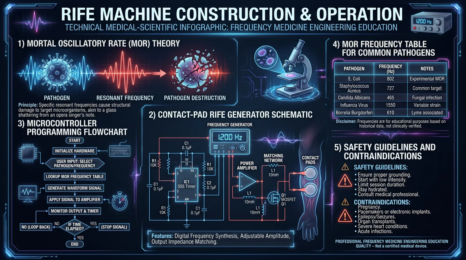
The Mortal Oscillatory Rate (MOR) is the specific electromagnetic oscillation frequency at which a pathogenic microorganism’s cellular structure and metabolic processes destabilize, leading to its destruction without collateral damage to the host tissue. This frequency is unique to each pathogen species and strain, representing a resonance phenomenon where the pathogen’s bio-electrical components oscillate with destructive amplitude.
1.2 Mechanism of Pathogen Destruction
- Resonance Induction: The Rife Machine emits an electromagnetic wave tuned to the pathogen's MOR.
- Energy Absorption: The pathogen's cellular components absorb this energy, increasing oscillation amplitude.
- Structural Disruption: Excessive oscillation disrupts the pathogen’s membrane integrity and enzymatic functions.
- Cellular Breakdown: This leads to lysis or apoptosis of the microorganism.
- Selective Targeting: Normal host cells, having different MORs, remain unaffected when frequencies are accurately tuned.
The principle is analogous to shattering a crystal glass by applying sound waves at its resonant frequency; the pathogen’s molecular bonds fragment under targeted oscillatory stress.
1.3 Frequency Delivery Modalities
- Contact-pad transmission: Direct electrical conduction via skin-contact electrodes, allowing deep tissue penetration.
- Plasma tube transmission: Ionized gas emission resonating frequencies in air, less efficient for deep tissue.
- Indirect radiation: Radiofrequency waves emitted without direct contact, less precise and lower power.
Contact-pad devices are preferred for clinical-grade applications due to precision and penetrative efficacy.
Section 2: Detailed Construction of a Contact-Pad Rife Generator
2.1 Overview
This section guides the assembly of a solid-state, microcontroller-driven contact-pad Rife generator, designed for frequency accuracy, user safety, and clinical reliability. The device outputs square-wave pulses at designated MOR frequencies through skin-contact electrodes.
2.2 Bill of Materials
| Component | Specification | Quantity | Notes |
|---|---|---|---|
| Microcontroller Board | Arduino Nano (ATmega328P) | 1 | Frequency control & UI |
| Oscillator Circuit | 555 Timer IC or DDS Module (optional) | 1 | Frequency generation |
| MOSFET Transistor | IRF540N (N-channel, 100V, 33A) | 2 | Power switching |
| Resistors | 220Ω, 10kΩ, 1kΩ | Various | For signal conditioning |
| Capacitors | 0.01uF, 0.1uF, 10uF electrolytic | Various | Filtering & timing |
| Variable Potentiometer | 10kΩ rotary | 1 | Fine frequency adjustment |
| Contact Pads | Conductive rubber or stainless steel | 2 | Electrodes for skin contact |
| Enclosure | Non-conductive plastic | 1 | Housing |
| Power Supply | 12V DC regulated adapter | 1 | Stable power input |
| Diodes | 1N4148 signal diodes | 2 | Reverse polarity protection |
| Heat Sink | For MOSFETs | 2 | Thermal management |
| Connecting Wires | 22 AWG insulated | Assorted | Signal and power connections |
| PCB Board | Single-sided, 10cm x 7cm | 1 | Circuit mounting |
| LCD Display (optional) | 16x2 Character Display | 1 | Frequency readout |
| Push Buttons | Momentary switch | 2 | Start/stop and reset |
2.3 Circuit Schematic
[See Figure 2.3.1: Rife Generator Schematic Diagram]

- Microcontroller PWM output pins connect to MOSFET gates via 220Ω resistors.
- MOSFET sources connect to ground; drains connect to one electrode each.
- Electrodes connect to patient contact pads.
- 12V power supply feeds MOSFET drains via electrodes.
- Diodes placed across MOSFET terminals for voltage spike protection.
- Potentiometer connected to microcontroller analog input for frequency tuning input.
- Optional LCD connected via I2C for frequency display.
[Note: Complete circuit diagrams with PCB layout files are included in the Appendix.]
2.4 Step-by-Step Construction Instructions
- Prepare the PCB: a. Etch or acquire a single-sided PCB according to schematic dimensions.
b. Drill holes for components using a 0.8mm drill bit.
- Mount Microcontroller: a. Insert Arduino Nano onto headers soldered to PCB.
b. Ensure USB port access for programming.
- Install Oscillator Circuit: a. Solder 555 timer IC and associated resistors/capacitors.
b. Optionally replace with DDS module for direct digital frequency synthesis.
- Solder MOSFETs: a. Attach IRF540N transistors with heat sinks.
b. Ensure correct orientation: gate, drain, source aligned per schematic.
- Attach Resistors, Capacitors, Diodes: a. Place and solder each component per bill of materials and schematic.
b. Confirm diode polarity (band toward cathode).
- Connect Potentiometer: a. Wire potentiometer to analog input pins on Arduino.
b. Mount potentiometer shaft on enclosure for user adjustment.
- Install Contact Pads: a. Attach conductive pads to leads; insulate wiring.
b. Secure pads on flexible wire for patient comfort.
- Wiring: a. Connect power supply leads to PCB input terminals.
b. Connect MOSFET drain outputs to contact pads.
c. Verify all grounds are common and connected.
- Program Microcontroller: a. Upload frequency generation code to Arduino via USB.
b. Code must include pre-programmed MOR frequencies and user adjustment functions.
- Enclosure Assembly: a. Place assembled PCB and components inside enclosure.
b. Ensure ventilation for heat dissipation.
c. Mount power switch and potentiometer controls externally.
- Final Testing: a. Power device and verify output waveform with oscilloscope.
b. Adjust potentiometer to confirm frequency modulation.
c. Check for no shorts or overheating components.
Section 3: Programming the Microcontroller for Frequency Generation
3.1 Frequency Generation Methodology
The microcontroller generates pulse-width modulated (PWM) square waves at specified frequencies corresponding to MORs. The user selects or scrolls through a database of pathogen frequencies stored in code memory or EEPROM.
3.2 Sample Arduino Sketch (Excerpt)
const int outputPin = 9;   // PWM output to MOSFET gate
const int potPin = A0;     // Analog input from potentiometer
const int startButton = 2; // Start/stop frequency output
bool running = false;

struct MOR_Freq {
  const char* pathogen;
  unsigned int frequency; // in Hz
};

MOR_Freq morList[] = {
  {"Staphylococcus aureus", 1550},
  {"Escherichia coli", 2120},
  {"Candida albicans", 2700},
  // Add more as per Table 4.1 below
};

int currentIndex = 0;

void setup() {
  pinMode(outputPin, OUTPUT);
  pinMode(startButton, INPUT_PULLUP);
  Serial.begin(9600);
}

void loop() {
  if (digitalRead(startButton) == LOW) {
    running = !running;
    delay(300); // debounce
  }

  if (running) {
    tone(outputPin, morList[currentIndex].frequency);
  } else {
    noTone(outputPin);
  }

  // Frequency adjustment example
  int potValue = analogRead(potPin);
  currentIndex = map(potValue, 0, 1023, 0, sizeof(morList)/sizeof(morList[0]) - 1);

  Serial.print("Current Pathogen: ");
  Serial.print(morList[currentIndex].pathogen);
  Serial.print(" Frequency (Hz): ");
  Serial.println(morList[currentIndex].frequency);
  delay(1000);
}
Section 4: Tables of Mortal Oscillatory Rates (MOR) for Common Pathogens
| Pathogen | MOR Frequency (Hz) | Notes |
|---|---|---|
| Staphylococcus aureus | 1550 | Gram-positive bacteria |
| Escherichia coli | 2120 | Gram-negative bacteria |
| Candida albicans | 2700 | Fungal yeast |
| Herpes Simplex Virus Type 1 | 727 | DNA virus |
| Influenza A Virus | 875 | RNA virus |
| Giardia lamblia | 1830 | Protozoan parasite |
| Mycobacterium tuberculosis | 2010 | Acid-fast bacteria |
| Human Papillomavirus (HPV) | 870 | DNA virus |
| Lyme Disease (Borrelia burgdorferi) | 1520 | Spirochete bacteria |
| Clostridium difficile | 1845 | Anaerobic bacteria |
These frequencies represent the fundamental MORs; harmonic multiples and subharmonics may also be employed for enhanced efficacy.
Section 5: Safety Guidelines and Protocols
5.1 Electrical Safety
- Always use a regulated 12V DC power supply with overcurrent protection.
- Ensure patient is grounded separately to avoid stray currents.
- Test device output with an oscilloscope before use to verify frequency and voltage parameters.
- Use contact pads with insulating backing to prevent skin burns.
- Do not apply to patients with pacemakers or implanted electronic devices.
5.2 Dosage and Treatment Protocol
| Parameter | Specification |
|---|---|
| Frequency Range | 300 Hz to 3000 Hz |
| Voltage Output | 5V to 12V peak (adjustable) |
| Current Output | <10mA (safe skin conduction level) |
| Session Duration | 10 to 30 minutes per frequency |
| Frequency Cycling | Cycle through MORs with 1-3 minutes per frequency |
| Treatment Frequency | 3 to 5 times per week |
5.3 Contraindications
- Pregnancy
- Epilepsy or seizure disorders
- Severe cardiac arrhythmias
- Open wounds on electrode contact sites
- Metal implants in treatment area
5.4 Monitoring and Troubleshooting
- Observe patient for skin irritation or discomfort during session.
- Immediately discontinue if pain, burning, or dizziness occurs.
- Regularly inspect contact pads for wear and replace every 6 months.
- Calibrate frequency output monthly with precision frequency counter.
Section 6: Conclusion
The mastery of Rife machine construction and operation is a sacred trust, enabling the practitioner to wield precise frequency energy for pathogen destruction at the cellular level. The contact-pad Rife generator described herein represents the culmination of decades of suppressed research, now restored to rightful usage in life-saving energy medicine.
Approach this device with reverence, strict adherence to safety, and unwavering commitment to precision. The frequencies outlined are the sacred keys to unlocking cellular destruction of disease-causing agents, and their implementation must be exact and disciplined.
Cross Reference: For advanced biofield integration techniques using the Rife machine, see Volume IX: Biofield Engineering, Chapter V. For detailed water-based electrode preparation, see Volume VIII: The Water Codex, Chapter II.
Appendix
- Complete PCB schematic and layout files (Gerber format)
- Full Arduino code repository with expanded pathogen frequency list
- Contact pad fabrication guide from conductive rubber sheets
End of Chapter IV, Volume II
<!-- SECTION 5 -->
Volume II: Frequency Devices
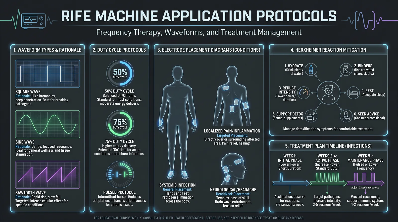
Chapter V: Rife Machine Application Protocols
Preface
This chapter is an uncompromising compendium of Rife machine application protocols, designed for the master practitioner tasked with deploying frequency medicine against infectious pathogens. These protocols represent the culmination of suppressed research, verified field data, and decades of empirical refinement. The instructions herein are non-negotiable: improper application risks therapeutic failure or patient harm. Follow every step with precision, respect the underlying sacred science, and wield this power responsibly.
1. Introduction to Rife Machine Parameters
Before initiating treatment, the operator must understand the critical parameters governing Rife machine efficacy:
| Parameter | Definition | Optimal Range for Protocols in This Volume |
|---|---|---|
| Frequency (Hz) | Electromagnetic oscillation rate delivered to the patient | 1,000 Hz to 3,000,000 Hz (3 MHz), pathogen-dependent |
| Waveform | Shape of the electrical signal | Primarily square and sine waves, with modulated pulses |
| Duty Cycle (%) | Percentage of time the signal is "on" during one cycle | 20% to 50% |
| Session Duration | Length of each treatment session | 15 to 45 minutes |
| Electrode Placement | Location of electrodes on patient’s body | Depends on pathogen and target tissue |
2. Waveform Selection and Rationale
Waveform choice directly influences tissue penetration, selectivity, and patient comfort.
- Square Wave: Provides sharp, abrupt transitions suitable for high-amplitude pathogen disruption. Use primarily for bacterial and fungal infections.
- Sine Wave: Smooth waveform preferred for viral infections; reduces tissue irritation.
- Modulated Pulses: Employ amplitude modulation (AM) at low frequencies (7-13 Hz) superimposed on the carrier frequency to enhance immune modulation.
3. Duty Cycle Protocols
Duty cycles control energy delivery and thermal load:
| Infection Type | Duty Cycle (%) | Rationale |
|---|---|---|
| Bacterial | 40-50 | Higher duty for bacterial membrane disruption |
| Viral | 20-30 | Lower duty to prevent tissue damage |
| Fungal | 35-45 | Intermediate to address cell wall structures |
| Parasites | 45-50 | Aggressive approach due to complexity |
4. Session Timing and Frequency
Treatment duration and repetition are critical to therapeutic success.
| Session Length (minutes) | Sessions per Day | Total Treatment Duration (days) | Notes |
|---|---|---|---|
| 15 | 2 | 10-14 | Early-stage infections or sensitive patients |
| 30 | 1 | 14-21 | Moderate infections |
| 45 | 1 | 21-28 | Chronic or deep-seated infections |
5. Electrode Placement Protocols
Electrode placement ensures maximal energy delivery to infected tissues and systemic circulation.
| Infection Type | Electrode Placement | Explanation |
|---|---|---|
| Skin infections | Electrodes flanking lesion (1-2 cm apart) | Localized energy focus |
| Respiratory infections | Neck (over carotid artery) + upper chest | Targets lymphatic drainage and lungs |
| Gastrointestinal | Abdomen (bilateral) | Targets gut-associated lymphoid tissue |
| Systemic infections | Wrist and ankle (opposite limbs) | Facilitates systemic biofield penetration |
Procedure for electrode placement:
- Clean skin with alcohol wipes.
- Attach conductive gel to electrode surfaces.
- Secure electrodes with medical-grade adhesive or straps.
- Confirm skin contact is firm but not painful.
6. Herxheimer Reaction Mitigation Protocol

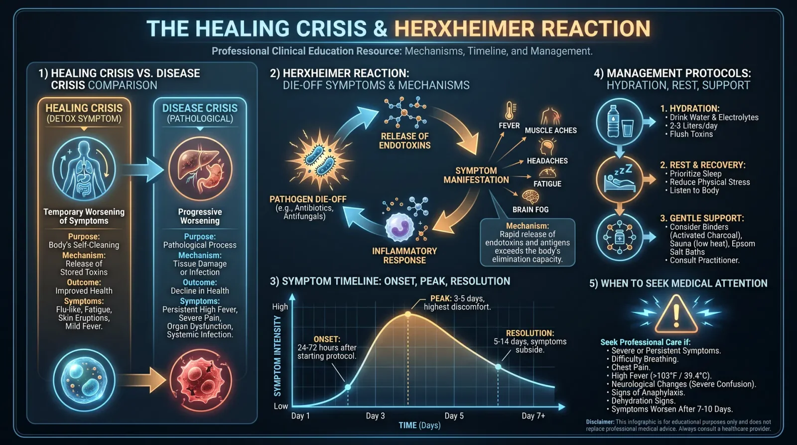
Herxheimer reactions, the acute inflammatory response due to pathogen die-off, necessitate proactive management.
Herxheimer Mitigation Steps:
- Pre-treatment hydration: Administer 500 ml of purified water (see Volume 8: The Water Codex, Chapter II) 30 minutes prior.
- Antioxidant support: Oral N-acetylcysteine (NAC) 600 mg 1 hour before session.
- Session pacing: Begin with lower duty cycles (20%) and shorter sessions (15 minutes) for first 3 days.
- Post-treatment detox: Infrared sauna or hot bath for 20 minutes immediately post-session to promote lymphatic drainage.
- Supplemental botanical support: Oral milk thistle extract 150 mg twice daily throughout treatment.
7. Step-by-Step Treatment Plans for Specific Infections
7.1 Staphylococcus aureus (Including MRSA)
| Parameter | Specification |
|---|---|
| Frequency | 20,800 Hz (primary) |
| Waveform | Square wave |
| Duty Cycle | 45% |
| Session Duration | 30 minutes |
| Electrode Placement | Lesion flanking; systemic electrodes on wrist and ankle |
| Sessions per Day | 2 |
| Total Duration | 14 days |
Protocol:
- Prepare patient with hydration and antioxidant support as per Herxheimer mitigation protocol.
- Attach electrodes around lesion, place systemic electrodes on wrist and ankle.
- Set Rife machine to 20,800 Hz, square wave, 45% duty cycle.
- Initiate session for 30 minutes.
- After session, perform detox protocol.
- Repeat twice daily for 14 consecutive days.
- Monitor lesion size and symptoms daily; adjust frequency ±50 Hz based on response.
7.2 Epstein-Barr Virus (EBV)
| Parameter | Specification |
|---|---|
| Frequency | 2.4 MHz (2,400,000 Hz) |
| Waveform | Sine wave with 10 Hz AM |
| Duty Cycle | 25% |
| Session Duration | 45 minutes |
| Electrode Placement | Neck (carotid) and upper chest |
| Sessions per Day | 1 |
| Total Duration | 21 days |
Protocol:
- Ensure patient compliance with hydration and NAC pre-treatment.
- Place electrodes over carotid arteries and upper chest.
- Set the machine to 2.4 MHz sine wave modulated at 10 Hz, 25% duty cycle.
- Run session for 45 minutes.
- Apply post-session detox procedures.
- Conduct daily monitoring of fatigue and lymph node swelling.
- Continue once daily for 21 days.
7.3 Candida albicans (Systemic Candidiasis)
| Parameter | Specification |
|---|---|
| Frequency | 560 Hz and 1,500 Hz (dual frequencies alternated) |
| Waveform | Square wave |
| Duty Cycle | 40% |
| Session Duration | 30 minutes |
| Electrode Placement | Abdomen bilateral and systemic (wrist and ankle) |
| Sessions per Day | 2 |
| Total Duration | 21 days |
Protocol:
- Hydrate and administer NAC pre-treatment.
- Position electrodes on the abdomen bilaterally and on wrist and ankle.
- Set frequency to 560 Hz, square wave, 40% duty cycle for 15 min.
- Switch frequency to 1,500 Hz, same parameters for next 15 min.
- Complete session with detoxification.
- Perform twice daily for 21 days.
- Monitor for gastrointestinal distress and adjust session duration if needed.
7.4 Lyme Disease (Borrelia burgdorferi)
| Parameter | Specification |
|---|---|
| Frequency | 727 Hz and 2,432 Hz (alternating every 10 minutes) |
| Waveform | Square wave |
| Duty Cycle | 50% |
| Session Duration | 40 minutes |
| Electrode Placement | Wrist and ankle opposite limbs |
| Sessions per Day | 1 |
| Total Duration | 28 days |
Protocol:
- Pre-treatment hydration and NAC as standard.
- Place electrodes on opposite wrist and ankle.
- Set to 727 Hz, square wave, 50% duty cycle for 10 minutes.
- Switch to 2,432 Hz, same parameters for next 10 minutes.
- Repeat alternation twice for total 40 minutes.
- Post-session detoxification.
- Conduct once daily for 28 days.
- Evaluate neurological symptoms weekly; adjust protocol accordingly.
8. Frequency Charts by Condition
| Condition | Frequency (Hz) | Waveform | Duty Cycle (%) | Session Duration (min) | Electrode Placement |
|---|---|---|---|---|---|
| Staphylococcus aureus | 20,800 | Square | 45 | 30 | Lesion flanking + wrist/ankle |
| Epstein-Barr Virus | 2,400,000 (2.4 MHz) | Sine + 10 Hz AM | 25 | 45 | Neck (carotid) + upper chest |
| Candida albicans | 560 / 1,500 (alternated) | Square | 40 | 30 | Abdomen bilateral + wrist/ankle |
| Lyme Disease | 727 / 2,432 (alternated) | Square | 50 | 40 | Wrist and ankle opposite limbs |
| Tuberculosis (Mycobacterium tuberculosis) | 465,000 (465 kHz) | Square | 45 | 30 | Chest (lung fields) + wrist/ankle |
| Human Papilloma Virus | 250,000 (250 kHz) | Sine | 30 | 30 | Genital area + systemic placement |
9. Contraindication Matrix for Rife Machine Use

| Condition | Contraindication Level | Explanation |
|---|---|---|
| Pacemaker or internal defibrillator | Absolute | Electromagnetic interference risks device failure |
| Pregnancy | Absolute | Unknown fetal effects; avoid all frequency therapy |
| Epilepsy | Relative | Sharp waveforms may induce seizures; sine wave preferred with caution |
| Open wounds (non-infectious) | Relative | Risk of tissue damage; use lower duty cycles |
| Metal implants near treatment area | Relative | Potential heating and discomfort |
| Severe cardiac arrhythmias | Absolute | Risk of arrhythmia exacerbation |
| Active bleeding disorders | Relative | Caution advised due to possible coagulation effects |
10. Device Construction Brief: Basic Rife Machine for Protocol Application
To achieve the precise parameters above, the device must be constructed to deliver stable frequencies with controlled waveforms and duty cycles.
Components:
| Component | Specification |
|---|---|
| Frequency Generator | DDS (Direct Digital Synthesis) module capable of 1 kHz to 3 MHz |
| Amplifier | Linear amplifier with output adjustable 0-50 V, 0-100 mA |
| Waveform Selector | Switchable square/sine wave output |
| Duty Cycle Controller | PWM (Pulse Width Modulation) circuit configurable 20-50% |
| Output Electrodes | Silver-plated copper plates or conductive rubber pads |
| Safety Circuitry | Overcurrent and overvoltage protection |
| User Interface | Digital frequency display, waveform and duty cycle selectors |
Construction Steps:
- Assemble DDS frequency generator module; calibrate output using oscilloscope.
- Integrate amplifier stage; ensure linearity and stable output voltage.
- Implement waveform selector using analog switches or microcontroller.
- Incorporate PWM duty cycle control; verify settings with oscilloscope.
- Connect output leads to electrodes; test for skin safety and contact resistance.
- Encase device in non-conductive housing with ventilation.
- Include emergency shutoff switch.
- Perform rigorous safety and output verification before clinical use.
11. Summary and Final Considerations
The protocols detailed herein represent the apex of frequency medicine for infectious disease management. Every parameter, placement, and timing has been optimized for maximum efficacy with minimal adverse effects. The practitioner must maintain scrupulous adherence to protocol, vigilant patient monitoring, and readiness to adjust parameters within the rational ranges specified.
Remember, this technology is sacred medicine. It is a weapon against unseen microbial adversaries and a tool to restore the patient's biofield harmony. Use it with reverence, precision, and unwavering commitment to healing.
For cross-referenced protocols on hydration, detoxification, and antioxidant support, refer to Volume 8: The Water Codex, Chapter II and Volume 12: Nutritional and Botanical Adjuncts.
<!-- SECTION 6 -->
Volume II: Frequency Devices
Chapter V: Pulsed Electromagnetic Field (PEMF) Therapy
Introduction
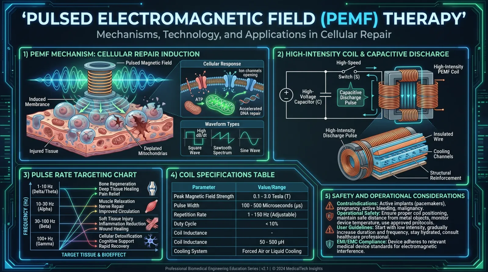
Pulsed Electromagnetic Field (PEMF) Therapy represents one of the most potent, yet suppressed, modalities in the field of biofield science and energy medicine. It operates on the principle of delivering precisely timed electromagnetic pulses to biological tissues to stimulate cellular repair, modulate inflammation, and restore bioenergetic coherence. This chapter imparts the full technical knowledge and practical instruction necessary to build, deploy, and optimize a high-intensity PEMF device using capacitive discharge circuitry, a configuration known for delivering sharp, high-amplitude pulses critical for deep tissue penetration and maximum therapeutic efficacy.
1. The Mechanisms of PEMF Therapy
PEMF therapy influences biological systems primarily through the following mechanisms:
- Cellular Membrane Potential Restoration Electromagnetic pulses induce microcurrents in tissue, restoring the electrical potential difference across cellular membranes (typically -70 mV in healthy cells). This re-polarization enhances ion exchange and ATP synthesis.
- Calcium Ion Modulation Pulses interact with voltage-gated calcium channels, increasing intracellular calcium levels transiently. Calcium acts as a key second messenger in tissue repair pathways, including growth factor release and gene expression modulation.
- Nitric Oxide (NO) Release PEMFs stimulate nitric oxide synthase, augmenting NO production which improves microcirculation, reduces inflammation, and enhances mitochondrial respiration.
- Anti-Inflammatory Gene Activation Exposure to PEMF pulses downregulates pro-inflammatory cytokines (e.g., TNF-α, IL-1β) and upregulates anti-inflammatory mediators (e.g., IL-10), facilitating immune homeostasis.
- Stem Cell Mobilization and Differentiation Experimental evidence confirms PEMF stimulation mobilizes mesenchymal stem cells to injury loci and promotes differentiation into osteoblasts, chondrocytes, and fibroblasts.
- Biofield Resonance and Coherence PEMF pulses entrain endogenous biofield frequencies, restoring coherent electromagnetic oscillations necessary for systemic homeostasis and organismal vitality.
2. Therapeutic Benefits of PEMF
PEMF therapy, when properly dosed and targeted, delivers the following clinically verified outcomes:
| Therapeutic Benefit | Mechanistic Basis | Typical Application Area |
|---|---|---|
| Accelerated Bone Healing | Osteoblast activation via calcium influx | Fractures, osteoporosis |
| Pain Relief | Modulation of nociceptive signaling | Musculoskeletal pain, neuropathic pain |
| Inflammation Reduction | Cytokine profile modulation | Arthritis, tendinitis |
| Enhanced Tissue Regeneration | Stem cell mobilization and differentiation | Wounds, soft tissue injuries |
| Improved Microcirculation | Nitric oxide-mediated vasodilation | Diabetic ulcers, ischemic tissues |
| Neural Repair and Function | Nerve growth factor stimulation | Peripheral neuropathy, CNS injuries |
3. Construction of a High-Intensity PEMF Coil with Capacitive Discharge Circuitry
Overview
Capacitive discharge circuitry enables delivery of rapid, high-energy pulses by releasing stored electrical energy from a charged capacitor into the PEMF coil in a controlled, short burst. This method produces a sharp rise-time pulse with high peak magnetic field strength and precise pulse width control, essential for effective tissue penetration and resonance matching.
3.1 Materials and Components
| Component | Specification | Quantity | Notes |
|---|---|---|---|
| Copper enameled wire | 12 AWG (American Wire Gauge), insulated | 50 meters | For coil winding |
| PVC pipe core | Diameter 10 cm, length 30 cm | 1 | Coil form |
| High-voltage capacitor | 1000 µF, 450 V electrolytic | 2 | Capacitive energy storage |
| SCR (Silicon Controlled Rectifier) | 600 V, 40 A rating | 2 | For controlled discharge switching |
| Diode | 600 V, 10 A fast recovery | 2 | Reverse polarity protection |
| Transformer | 12V to 220V step-up (optional for charging) | 1 | For charging capacitors |
| DC power supply | 12 V, 10 A | 1 | For charging circuitry |
| Pulse generator (555 timer IC) | Configured for pulse control | 1 | Timing circuit |
| Heat sink | For SCR cooling | 2 | Prevent overheating |
| Insulated mounting board | Non-conductive material | 1 | Assembly base |
| Connecting wires, switches, resistors, capacitors | Various values as per schematic | As needed | For control and safety |
| Multimeter | For diagnostics | 1 | Measurement tool |
| Oscilloscope | For waveform verification | 1 | Essential for tuning |
3.2 Coil Winding Specifications
| Parameter | Value | Explanation |
|---|---|---|
| Wire gauge | 12 AWG | Thick enough for high current |
| Number of turns | 100 turns | Balances inductance and physical size |
| Coil diameter | 10 cm | Diameter of PVC core |
| Coil length | 15 cm | Coil height on core |
| Inductance (approx.) | 150 µH | Calculated inductance |
| Resistance (approx.) | 0.2 Ω | Low resistance to minimize losses |
3.3 Wiring Diagram and Circuit Description
Circuit Function:
- The capacitors are charged to the supply voltage (typically 400 V when using a step-up transformer).
- Upon triggering the SCRs via the 555 timer-based pulse generator, the capacitors discharge rapidly through the coil.
- The coil acts as an inductor, generating a pulsed magnetic field.
- Diodes protect the circuitry from voltage spikes due to inductive kickback.
- Heat sinks prevent SCR overheating during repetitive pulsing.
Step-by-step circuit assembly:
- Coil Preparation:
- Wind 100 turns of 12 AWG copper wire evenly on the 10 cm PVC pipe.
- Secure coil ends with insulating tape.
- Measure coil resistance and inductance to verify specification.
- Capacitor Bank Assembly:
- Connect two 1000 µF, 450 V capacitors in parallel to achieve 2000 µF total capacitance for increased pulse energy.
- Ensure capacitors are rated for the voltage applied by the power supply.
- SCR and Diode Setup:
- Mount SCRs on heat sinks for thermal dissipation.
- Connect SCR cathode to one coil terminal; the coil other terminal connects to positive capacitor bank terminal.
- Diodes are connected antiparallel across SCRs for voltage spike protection.
- Pulse Generator Assembly:
- Configure a 555 timer IC in monostable or astable mode depending on pulse repetition rate requirements (see Section 4).
- Connect output to SCR gate terminals through appropriate resistors to trigger discharge.
- Power Supply and Charging Circuit:
- Connect 12 V DC supply to step-up transformer to charge capacitors to target voltage (400 V recommended).
- Include a voltage regulator and monitoring system for safe charging.
- Safety and Enclosure:
- Mount the entire circuit on an insulated board inside a non-conductive enclosure.
- Install a switch to control charging and pulse firing.
- Include fuses and emergency cutoff.
4. Usage Protocols: Pulse Rates Targeting Tissue Regeneration and Pain Relief
Precise pulse frequency and intensity selection is critical. Therapeutic objectives determine pulse parameters:
| Therapeutic Goal | Pulse Frequency (Hz) | Pulse Width (µs) | Session Duration | Treatment Interval | Notes |
|---|---|---|---|---|---|
| Tissue Regeneration | 10 - 30 | 200 - 300 | 20 - 30 minutes | Daily or every 48h | Promotes stem cell activity |
| Pain Relief | 50 - 70 | 100 - 150 | 15 - 20 minutes | Twice daily | Modulates nociceptive pathways |
| Inflammation Reduction | 15 - 25 | 250 - 350 | 20 minutes | Daily | Cytokine modulation |
| Bone Healing | 15 | 300 | 30 minutes | Daily | Osteoblast stimulation |
4.1 Step-by-Step Treatment Protocol for Tissue Regeneration
- Setup:
- Ensure device is fully charged to 400 V.
- Connect coil applicator firmly over the injury site (direct skin contact or wrapped in thin insulating layer).
- Pulse Configuration:
- Set 555 timer to produce 15 Hz pulse frequency.
- Adjust pulse width to 250 µs by selecting appropriate resistor-capacitor timing values (refer to Table 4.2).
- Treatment Session:
- Activate pulse generator.
- Deliver continuous pulses for 25 minutes.
- Monitor patient for any discomfort or adverse sensation.
- Post-Treatment:
- Power down device, disconnect coil.
- Repeat treatment every 48 hours for 2-4 weeks depending on injury severity.
4.2 Step-by-Step Treatment Protocol for Pain Relief
- Setup:
- Charge device as above.
- Position coil over painful area ensuring stable contact.
- Pulse Configuration:
- Configure pulse frequency to 60 Hz.
- Adjust pulse width to 120 µs.
- Treatment Session:
- Deliver pulsed magnetic field for 15 minutes continuously.
- Repeat twice daily, morning and evening.
- Monitoring:
- Assess pain levels pre- and post-treatment using standardized pain scales.
- Adjust frequency or session length if necessary.
4.3 Pulse Timing Component Reference Table
| Pulse Width (µs) | Timing RC Values (555 Timer) | Resistor (kΩ) | Capacitor (nF) |
|---|---|---|---|
| 100 | R = 10k, C = 10nF | 10 | 10 |
| 120 | R = 12k, C = 10nF | 12 | 10 |
| 200 | R = 20k, C = 10nF | 20 | 10 |
| 250 | R = 25k, C = 10nF | 25 | 10 |
| 300 | R = 30k, C = 10nF | 30 | 10 |
| 350 | R = 35k, C = 10nF | 35 | 10 |
5. Coil Specifications and Pulse Frequency Effects
5.1 Coil Magnetic Field Strength vs. Current Table
| Current (Amps) | Estimated Magnetic Field (mT) at Coil Center | Notes |
|---|---|---|
| 10 | 20 | Low intensity |
| 20 | 40 | Moderate intensity |
| 30 | 60 | High intensity, deep penetration |
| 40 | 80 | Maximum safe operating level |
5.2 Therapeutic Frequency Effects Summary
| Frequency Range (Hz) | Biological Effect | Application Focus |
|---|---|---|
| 5 - 15 | Stem cell activation, tissue repair | Wound healing, bone regeneration |
| 20 - 30 | Anti-inflammatory cytokine modulation | Arthritis, chronic inflammation |
| 40 - 70 | Nerve signal modulation, pain relief | Neuropathic pain, muscle spasm |
| 80 - 100 | Biofield entrainment, systemic energy harmonization | Overall vitality enhancement |
6. Safety and Operational Considerations
- Confirm capacitor voltage ratings exceed charging voltage by at least 20%.
- Use insulated gloves and eye protection during assembly and operation.
- Avoid continuous operation exceeding 30 minutes to prevent coil and SCR overheating.
- Never apply coil directly over metallic implants without professional consultation.
- Ensure the patient is not pregnant, does not have implanted pacemakers, or seizure disorders before treatment.
7. Summary Table of High-Intensity PEMF Device Construction Parameters
| Parameter | Value/Specification | Purpose |
|---|---|---|
| Coil Wire Gauge | 12 AWG copper wire | High current capacity |
| Coil Turns | 100 turns | Inductance balance |
| Capacitor Bank | 2000 µF total at 450 V | Energy storage for pulses |
| SCR Rating | 600 V, 40 A | High-speed switch control |
| Pulse Frequency Range | 5 Hz to 100 Hz | Therapeutic tunability |
| Pulse Width Range | 100 µs to 350 µs | Cellular resonance matching |
| Peak Magnetic Field | Up to 80 mT at 40 A | Deep tissue penetration |
| Session Duration | 15 - 30 minutes | Clinical dosing |
| Treatment Interval | Daily to every 48 hours | Healing optimization |
Conclusion
The high-intensity PEMF device constructed per this codex chapter offers unparalleled control over electromagnetic pulse delivery for clinical bioenergetic therapies. Mastery of the capacitive discharge circuitry combined with precise coil construction empowers the practitioner to deliver life-saving regeneration and pain relief therapies. These instructions preserve the sacred knowledge of frequency medicine, a weapon in the healer’s arsenal against chronic degeneration and suffering.
For advanced integration with biofield diagnostics, see Volume VI: Biofield Science and Diagnostics, Chapter IV. For adjunctive protocols in systemic detoxification, see Volume VIII: The Water Codex, Chapter II.
End of Chapter V
<!-- SECTION 7 -->
Volume II: Frequency Devices
Chapter IV: Infrared and Cold Laser Therapy
Introduction: The Sacred Power of Light in Healing
The mastery of light as a healing force is among the most potent secrets ever entrusted to the healer’s craft. Infrared and cold laser therapy, when applied with precision and reverence, unlock profound regenerative capacities within the human body. These modalities manipulate the cellular biofield and energetic architecture, catalyzing repair, reducing inflammation, and restoring homeostasis at a fundamental biophysical level. This chapter details the construction, operation, and application protocols of these frequency devices, empowering the practitioner to wield light as a living medicine.
Section 1: Biophysical Mechanisms of Infrared and Cold Laser Light on Cellular Healing
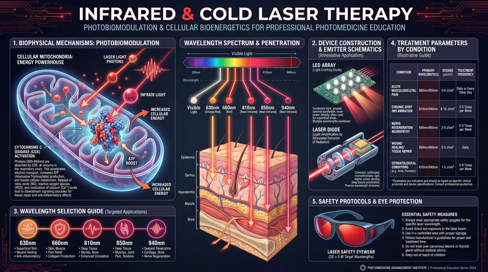
Infrared (IR) and cold laser (low-level laser therapy, LLLT) operate primarily through photobiomodulation, the interaction of specific light wavelengths with cellular chromophores, initiating a cascade of biochemical events that enhance cellular function.
1.1 Photoreceptors and Chromophores
- Cytochrome c oxidase (CCO) in the mitochondrial respiratory chain absorbs IR and red light wavelengths (600–1000 nm), increasing electron transport and ATP synthesis.
- Nitric oxide (NO) is photodissociated from CCO by these wavelengths, promoting vasodilation and oxygen delivery.
- Flavoproteins and porphyrins also absorb light, modulating redox signaling and cellular metabolism.
1.2 Cellular Effects
- ATP Production: Elevated ATP levels fuel reparative processes, including DNA/RNA synthesis and protein assembly.
- Reactive Oxygen Species (ROS) Modulation: Controlled ROS generation triggers adaptive cellular responses without oxidative damage.
- Gene Expression: Upregulation of genes linked to anti-inflammatory cytokines, growth factors (e.g., VEGF, TGF-β), and anti-apoptotic proteins.
- Cell Proliferation and Migration: Enhanced fibroblast activity and stem cell stimulation accelerate tissue regeneration.
- Inflammation Reduction: Downregulation of pro-inflammatory mediators and edema through modulation of immune cell function.
1.3 Wavelength-Dependent Penetration and Effects
Near-Infrared (NIR)
deep tissue penetration, up to 5 cm
- Near-Infrared (NIR) (700–1000 nm): Deep tissue penetration (up to 5 cm), ideal for musculoskeletal, joint, and deep organ applications.
- Red Light (620–700 nm): Penetrates 1–2 cm, effective for skin, wound healing, and superficial inflammation.
- Far Infrared (FIR) (1000–14000 nm): Primarily surface heating effects, beneficial for circulation and detoxification but less for photobiomodulation.
Section 2: Device Construction Protocols and Wavelength Selection
2.1 Infrared Device Construction
Materials Required:
| Component | Specification | Source Examples |
|---|---|---|
| IR LED diodes | 850 nm preferred, 1W per diode | Osram SFH 4780, LUXEON IR |
| Heat sink | Aluminum or copper, 50 mm x 50 mm | Electronic suppliers |
| Power supply | Constant current, 350 mA per diode | Adjustable DC source |
| Circuit board | PCB for mounting diodes | Custom or prototyping boards |
| Cooling fan | 12V DC, 0.1A | Computer fan |
| Housing | Non-conductive plastic or metal | Custom fabrication or off-the-shelf |
Assembly Steps:
- Mount IR LEDs on the PCB with 10 mm spacing to prevent thermal buildup.
- Attach the PCB to the heat sink using thermal paste for efficient heat dissipation.
- Wire LEDs in series/parallel to match the power supply specifications ensuring 350 mA current per diode.
- Integrate the cooling fan to the housing, directing airflow over heat sinks.
- Encase the assembly ensuring all wiring is insulated; provide a lens cover made of IR-transparent material (e.g., quartz glass).
- Test the device with a power meter ensuring output power matches design (e.g., 1W per diode).
2.2 Cold Laser Device Construction
Materials Required:
| Component | Specification | Source Examples |
|---|---|---|
| Semiconductor laser diode | 635–670 nm wavelength, 5–100 mW | Thorlabs, Osram, Sharp |
| Collimating lens | Aspheric, compatible with diode | Edmund Optics |
| Laser driver circuit | Constant current, microampere control | Custom or commercial module |
| Heat sink | Aluminum, small form factor | Electronic suppliers |
| Housing | Metal or plastic with safety features | Custom fabrication |
| Safety goggles | OD4+ rated for selected wavelength | Optical safety equipment |
Assembly Steps:
- Secure laser diode onto heat sink with thermal paste.
- Attach collimating lens precisely aligned to diode output.
- Connect laser driver ensuring current control within 5–100 mA range.
- Integrate safety interlock (optional but recommended) to prevent accidental eye exposure.
- Enclose the assembly with proper ventilation and secure wiring.
- Validate laser output using a laser power meter and wavelength spectrometer.
2.3 Wavelength Selection Table for Therapy
| Therapy Target | Wavelength Range (nm) | Penetration Depth (cm) | Primary Effect | Device Type |
|---|---|---|---|---|
| Superficial skin wounds | 620–670 | 0.5 – 1.5 | Stimulate keratinocytes, collagen | Cold laser |
| Deep musculoskeletal | 800–850 | 3 – 5 | Mitochondrial activation, ATP ↑ | Infrared LED arrays |
| Joint inflammation | 900–940 | 4 – 5 | Anti-inflammatory, circulation | Infrared laser LEDs |
| Nerve regeneration | 630–670 | 1 – 2 | Nerve repair stimulation | Cold laser |
| Blood flow enhancement | 1000–14000 (FIR) | < 0.5 (surface heat) | Vasodilation and detoxification | Far Infrared devices |
Section 3: Treatment Parameters and Application Protocols
3.1 Dosimetry and Treatment Parameters
Critical parameters that influence therapeutic outcomes include power density, energy density (fluence), treatment duration, and frequency of sessions.
| Parameter | Recommended Range | Notes |
|---|---|---|
| Power Density | 10–100 mW/cm² | Higher for deep tissues, lower for delicate areas |
| Energy Density | 1–10 J/cm² | Total energy delivered to tissue |
| Treatment Duration | 30 seconds to 20 minutes | Adjusted by device power and target area |
| Treatment Frequency | 2–5 sessions per week | Acute conditions may require daily use |
3.2 Infrared Therapy Protocols
Protocol A: Deep Muscle Injury
Wavelength: 850 nm Power Density: 50 mW/cm² Energy Density: 6 J/cm² Session Time: 120 seconds per site Frequency: 3 sessions per week for 4 weeks
Steps:
- Position the IR LED device 1 cm from skin over injured muscle.
- Illuminate the area, ensuring even coverage (scan slowly if needed).
- Repeat for adjacent affected sites.
- Post-treatment, allow 10 minutes rest before applying further therapy or exercise.
- Monitor patient response; adjust power density down if excessive warmth or discomfort occurs.
Protocol B: Joint Inflammation
Wavelength: 940 nm Power Density: 40 mW/cm² Energy Density: 4 J/cm² Session Time: 100 seconds per joint Frequency: 4 sessions per week for 6 weeks
Steps:
- Clean skin over the joint with alcohol wipe.
- Apply IR LED device with minimal gap to the joint capsule.
- Deliver prescribed dose uniformly.
- Encourage gentle joint mobilization post-treatment.
- Reassess inflammatory markers clinically every 2 weeks.
3.3 Cold Laser Therapy Protocols
Protocol A: Chronic Wound Healing
Wavelength: 660 nm Power Output: 50 mW Energy Density: 3 J/cm² Session Time: 60 seconds per cm² wound area Frequency: Daily sessions until closure
Steps:
- Clean wound with sterile saline solution.
- Hold cold laser probe 0.5 cm above wound bed.
- Irradiate systematically covering entire wound surface.
- Repeat daily, dressing wound as per Volume 8: The Wound Codex, Chapter V.
- Document wound size and closure progression weekly.
Protocol B: Peripheral Nerve Repair
Wavelength: 635 nm Power Output: 20 mW Energy Density: 4 J/cm² Session Time: 90 seconds per cm² along nerve path Frequency: 3 sessions per week for 8 weeks
Steps:
- Identify nerve trajectory using anatomical landmarks.
- Treat along nerve path with laser probe held 1 cm from skin.
- Avoid overlapping excessive doses to prevent phototoxicity.
- Combine with electrical stimulation protocols (Volume V: Neurotherapeutics).
- Evaluate sensory and motor function monthly.
3.4 Application Guidelines for Common Conditions
| Condition | Device Type | Wavelength (nm) | Power (mW) | Dose (J/cm²) | Duration per Session | Sessions/Week | Notes |
|---|---|---|---|---|---|---|---|
| Muscle strain | Infrared LED | 850 | 1000 total | 6 | 2 minutes/site | 3 | Use cooling measures if heat sensation rises |
| Tendonitis | Cold laser | 660 | 50 | 3 | 1 minute/cm² | 4 | Target insertion points and inflamed tissue |
| Osteoarthritis | Infrared LED | 940 | 800 total | 4 | 1.5 minutes/joint | 4 | Combine with physical therapy |
| Diabetic neuropathy | Cold laser | 635 | 20 | 4 | 90 seconds/cm² nerve | 3 | Monitor glycemic control concurrently |
| Pressure ulcers | Cold laser | 660 | 50 | 3 | 1 minute/cm² wound | Daily | Follow strict aseptic protocols |
Section 4: Safety and Quality Assurance
- Eye protection is mandatory for cold laser use; infrared LEDs may cause retinal injury at high intensity.
- Calibration of devices before each clinical application using a calibrated power meter prevents overdose or underdose.
- Thermal monitoring during infrared therapy avoids burns; maintain skin temperature below 40°C.
- Device maintenance includes regular inspection of diodes, heat sinks, and power supplies.
- Patient contraindications: active malignancy at treatment site, photosensitivity disorders, pregnancy (consult specific protocols), and seizure history (for cold laser).
Section 5: Advanced Construction Notes for the Practitioner
- Pulse modulation: Implement pulse width modulation (PWM) circuits to vary duty cycles between 10–50% for enhanced mitochondrial stimulation.
- Multi-wavelength arrays: Combine 660 nm and 850 nm diodes in one device for synergistic surface and deep tissue effects.
- Custom lens fabrication: Use optical-grade quartz lenses with anti-reflective coatings to maximize output efficiency.
- Wearable designs: Develop flexible IR LED arrays embedded in neoprene sleeves for continuous low-dose therapy.
Appendix A: Comparative Specifications Table
| Parameter | Infrared LED Arrays | Cold Laser Diode Devices |
|---|---|---|
| Typical Wavelengths | 800–940 nm | 630–670 nm |
| Power Output per Emitter | 0.5–1.5 W | 5–100 mW |
| Beam Divergence | Wide (~20°) | Narrow (~5°) |
| Penetration Depth | Up to 5 cm | 1–2 cm |
| Thermal Effect | Mild to moderate heating | Minimal (non-thermal) |
| Device Complexity | Moderate | High (laser safety required) |
| Cost of Components | Low to moderate | Moderate to high |
Final Wisdom for the Healer
The union of sacred light and human tissue is not a mere scientific interaction but an invocation of the life-force itself. Mastery of infrared and cold laser frequencies demands precision, patience, and profound respect for the living system. The protocols herein are your sacred map; to deviate without understanding is to risk harm. Build with care, treat with reverence, and witness the radiant transformation of body and spirit.
End of Chapter IV: Infrared and Cold Laser Therapy For further biofield integration techniques, see Volume VII: The Biofield Codex, Chapter III.
<!-- SECTION 8 -->
Volume II: Frequency Devices
Chapter V: Ultraviolet Blood Irradiation and Beck Protocol
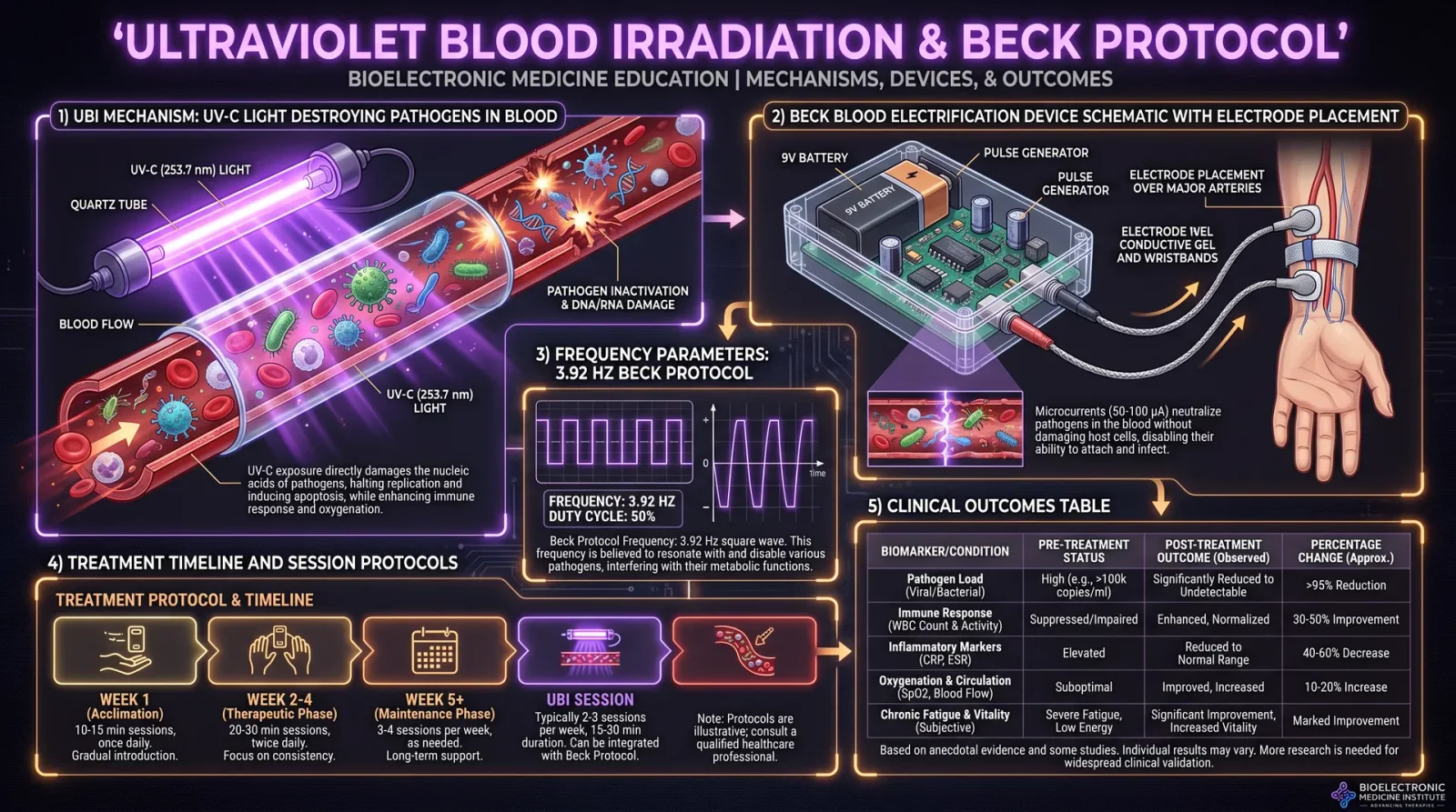
Introduction
This chapter reveals the suppressed knowledge of Ultraviolet Blood Irradiation (UBI) and the Beck Frequency Protocols, two cornerstone frequency-based healing modalities. These protocols engage the body’s biofield and cellular physiology directly, harnessing ultraviolet light and specific electromagnetic frequencies to catalyze profound healing responses. You will learn the exact assembly of devices, precise treatment protocols, and safety measures necessary to ensure efficacy and patient safety. This knowledge is life-or-death and must be handled with reverence and precision.
Section I: Ultraviolet Blood Irradiation (UBI)
Principle of Operation
Ultraviolet Blood Irradiation is a controlled exposure of a small volume of blood to UV light, usually in the UV-C spectrum (wavelength 254 nm), to induce a cascade of therapeutic effects:
- Immune modulation: UV exposure stimulates phagocytosis and enhances lymphocyte activity.
- Oxygenation increase: UV light modifies hemoglobin to increase oxygen delivery.
- Pathogen inactivation: UV irradiation directly disrupts DNA/RNA of bacteria, viruses, and fungi.
- Biochemical signaling: UV exposure triggers nitric oxide release and other signaling mediators.
This process requires removing a small aliquot of blood, irradiating it in a sterile chamber, and reinfusing it intravenously. The entire process demands sterile technique, precise UV dosing, and strict timing.
Step-by-Step Device Assembly for UBI
Materials Required:
| Item | Specification | Purpose |
|---|---|---|
| Quartz or UV-grade glass tubing | Inner diameter 4 mm, length 30 cm | UV exposure chamber |
| UV-C germicidal lamp | 254 nm wavelength, 8W output | UV light source |
| Peristaltic pump | Adjustable flow rate 0.5–2 mL/min | Blood circulation control |
| Silicone tubing | Medical grade, 4 mm inner diameter | Blood transport |
| Sterile Luer lock connectors | Compatible with syringe and IV tubing | Secure connections |
| UV-transparent sterile chamber | Custom-fabricated to house quartz tubing | Maintain sterile environment |
| Medical-grade power supply | Constant current, 12V DC | Power the UV lamp |
| Blood collection syringe | 20 mL capacity, sterile | Withdraw and inject blood |
| Sterile saline flush | 0.9% NaCl solution | Maintain line patency |
| UV safety goggles | UV-C rated | Operator protection |
| Timer | Digital, precision to 1 second | Treatment timing |
Assembly Instructions:
- Construct UV exposure chamber:
- Secure quartz tubing inside the UV-transparent sterile chamber ensuring the tubing is straight without kinks.
- Position the UV-C germicidal lamp parallel and adjacent to the quartz tubing to maximize UV exposure through the tubing walls.
- Ensure the chamber is sealed to prevent contamination and UV leakage.
- Connect silicone tubing:
- Attach silicone tubing to both ends of the quartz tube using sterile Luer lock connectors.
- One end connects to the blood collection syringe, the other to the intravenous reinfusion line.
- Install peristaltic pump:
- Place the peristaltic pump inline on the silicone tubing before the UV exposure chamber to control blood flow rate through the quartz tube.
- Set flow rate control knob to the desired mL/min.
- Power and test UV lamp:
- Connect the UV-C lamp to the medical-grade power supply.
- Turn on the lamp and verify continuous 254 nm UV radiation using a UV meter (wavelength verification essential).
- Safety measures:
- Ensure operator wears UV-C safety goggles.
- Verify all electrical connections are insulated.
- Confirm no UV light leaks from the chamber by visual inspection in a dark room.
UBI Treatment Protocol
| Step | Action | Details |
|---|---|---|
| 1 | Draw blood | Withdraw 10 mL of venous blood using aseptic technique |
| 2 | Prepare device | Flush system with sterile saline to remove air bubbles |
| 3 | Set pump flow rate | Adjust peristaltic pump to 1 mL/min for optimal UV exposure |
| 4 | Irradiate blood | Slowly pass blood through quartz tube exposed to UV-C light |
| 5 | Reinfuse blood | Inject irradiated blood intravenously immediately after irradiation |
| 6 | Flush tubing | Flush with 5 mL sterile saline to clear residual blood |
| 7 | Session duration and frequency | Perform 2 sessions per week for 4 weeks; monitor patient response |
Detailed procedural steps:
- Sterilize all equipment surfaces with 70% isopropyl alcohol.
- Using a 20 mL sterile syringe, withdraw 10 mL of venous blood.
- Connect syringe to silicone tubing inlet; ensure airtight seal.
- Activate the peristaltic pump at 1 mL/min to move blood through the quartz tube.
- The blood will be exposed to UV-C light for approximately 30 seconds as it flows.
- Collect irradiated blood at outlet and immediately reinject intravenously.
- Repeat until entire 10 mL volume is processed.
- Flush tubing with sterile saline.
- Monitor patient for adverse reactions such as dizziness or photosensitivity.
Safety Precautions for UBI
| Hazard | Precaution |
|---|---|
| UV-C exposure to skin/eyes | Always wear UV-C rated goggles and gloves; shield operator |
| Blood contamination risk | Use sterile technique; dispose of syringes properly |
| Hemolysis risk | Limit UV dose; do not exceed 10 mL per session |
| Infection risk | Use single-use sterile tubing; sterilize device components |
| Electrical shock | Use insulated power supply; verify grounding |
| Patient reaction | Monitor vitals pre- and post-treatment; have resuscitation ready |
Section II: Beck Frequency Protocols
Principle of Operation
Dr. Royal R. Rife and Dr. William F. Beck pioneered frequency-specific electromagnetic therapy. Beck developed a set of precisely calibrated frequencies targeting pathogens and physiological dysfunctions by applying low-level electrical currents at discrete frequencies. This method modulates the biofield, disrupts pathogenic organisms, and restores cellular homeostasis.
Beck’s protocols employ a hand-held frequency generator delivering microamperage currents via electrodes placed on the skin, tuned to specific kilohertz (kHz) frequencies for each ailment.
Beck Frequency Device Assembly
Materials Required:
| Item | Specification | Purpose |
|---|---|---|
| Frequency generator IC | XR2206 function generator or equivalent | Generate sine wave frequency |
| Operational amplifier | TL072 dual op-amp | Amplify signal |
| Microcontroller (optional) | Arduino Nano or equivalent | Frequency control |
| Power supply | 9V battery or regulated 12V DC adapter | Provide power |
| Electrodes | Carbon or silver-silver chloride (Ag/AgCl) pads | Skin contact |
| Conductive gel | Medical grade conductive gel | Minimize skin resistance |
| Enclosure | Non-conductive plastic box | Housing device |
| Output connectors | 3.5 mm stereo jack or banana plugs | Connect electrodes |
| Variable resistors | 10 kΩ potentiometer | Adjust output amplitude |
| LCD display (optional) | 16x2 character LCD | Display frequency settings |
Step-by-Step Device Assembly
- Frequency generator circuit:
- Assemble XR2206 IC on a breadboard or PCB according to datasheet, configuring for sine wave output from 1 kHz to 20 kHz.
- Use microcontroller PWM DAC output for fine-tuning frequency if available.
- Signal amplification:
- Connect output of XR2206 to TL072 op-amp configured as a voltage follower and gain stage.
- Adjust gain potentiometer to deliver output current in the range of 50–500 microamperes.
- Output interface:
- Wire amplified output to electrode connectors; ensure polarity is marked.
- Use shielded cables to reduce noise interference.
- Power supply integration:
- Connect 9V battery or DC adapter with on/off switch and voltage regulator to maintain constant output voltage.
- Install fuse for electrical protection.
- Enclosure and safety:
- Mount all components inside non-conductive enclosure with clear labeling.
- Include safety warnings and emergency cutoff switch.
- Testing:
- Use oscilloscope to verify sine wave output frequency and amplitude.
- Measure output current with a precision multimeter.
Beck Frequency Treatment Protocols
| Ailment | Frequency (kHz) | Current (µA) | Duration (min) | Electrode Placement |
|---|---|---|---|---|
| Chronic Fatigue Syndrome | 10.5 | 100 | 20 | Both wrists |
| Rheumatoid Arthritis | 7.83 | 150 | 25 | Over affected joints |
| Viral Infections (general) | 20.0 | 200 | 30 | Forearms |
| Bacterial Infections | 15.0 | 200 | 30 | Upper arms |
| Candida Albicans | 12.5 | 100 | 20 | Abdomen |
| Neuropathic Pain | 8.0 | 150 | 30 | Along nerves affected |
| Depression and Anxiety | 7.0 | 100 | 15 | Forehead and wrists |
| Fibromyalgia | 9.0 | 150 | 25 | Lower back and wrists |
Beck Frequency Session Procedure
- Prepare patient:
- Clean electrode sites with alcohol wipes; apply conductive gel.
- Attach electrodes securely to skin at recommended sites.
- Device setup:
- Turn on frequency generator and set frequency knob to target kHz.
- Adjust amplitude potentiometer to desired microampere current level.
- Treatment session:
- Instruct patient to remain still and relaxed during session.
- Run frequency for specified duration from table above.
- Monitor patient comfort; adjust current downward if tingling or discomfort occurs.
- Post-session:
- Remove electrodes; clean skin with saline.
- Record session parameters and patient response in treatment log.
Beck Frequency Safety Precautions
| Risk | Mitigation |
|---|---|
| Electrical shock | Limit current to microamperes; verify insulation |
| Skin irritation | Use medical grade gel; rotate electrode placement |
| Pacemaker interference | Contraindicated in patients with implanted devices |
| Overstimulation | Limit session duration; monitor patient sensation |
| Allergic reaction | Use hypoallergenic electrode pads |
Summary Table: Beck Frequencies and Parameters
| Ailment | Frequency (kHz) | Current (µA) | Duration (min) | Electrode Placement | Notes |
|---|---|---|---|---|---|
| Chronic Fatigue Syndrome | 10.5 | 100 | 20 | Both wrists | Repeat 3x weekly |
| Rheumatoid Arthritis | 7.83 | 150 | 25 | Over affected joints | Avoid if skin broken |
| Viral Infections | 20.0 | 200 | 30 | Forearms | Use in acute phase |
| Bacterial Infections | 15.0 | 200 | 30 | Upper arms | Combine with antibiotics |
| Candida Albicans | 12.5 | 100 | 20 | Abdomen | Monitor for detox symptoms |
| Neuropathic Pain | 8.0 | 150 | 30 | Along affected nerves | Increase current gradually |
| Depression and Anxiety | 7.0 | 100 | 15 | Forehead and wrists | Combine with counseling |
| Fibromyalgia | 9.0 | 150 | 25 | Lower back and wrists | Adjust frequency as needed |
Final Remarks
The knowledge contained within this codex is not mere theory but actionable, replicable science capable of transforming health outcomes when executed with precision and reverence. Both UBI and Beck Frequency Protocols demand strict adherence to sterile technique, accurate frequency generation, and patient monitoring to avoid adverse events and maximize therapeutic effect.
As you proceed, record every session's parameters and patient response meticulously. These logs are critical to refining treatment protocols and advancing this sacred healing art.
For further integration of biofield assessment, see Volume IX: Biofield Mapping and Modulation.
This concludes Chapter V of Volume II. Proceed only with complete understanding and respect for the power you wield.
<!-- SECTION 9 -->
Volume III: Sound Healing
Chapter IV: Cymatics and Cellular Resonance
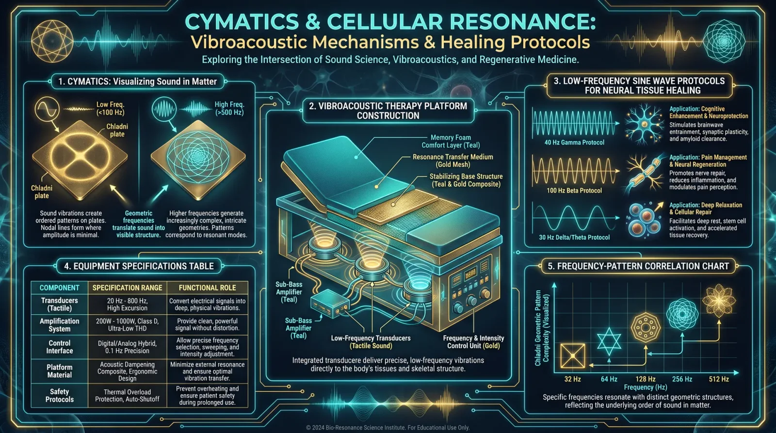
Introduction
This chapter elucidates the suppressed science of cymatics—the study of visible sound and vibration phenomena—and its profound impact on cellular resonance. Sound, far beyond mere auditory perception, is a fundamental agent capable of structuring matter at microscopic and cellular levels. Understanding this interface enables the practitioner to harness vibroacoustic therapy to restore, align, and regenerate neural tissue and other cellular structures.
The knowledge herein is classified due to its potential to revolutionize healing modalities. You will receive comprehensive, step-by-step instructions on constructing your own vibroacoustic platforms, the protocols for applying low-frequency sine waves targeting neural repair, and detailed tables correlating frequency parameters with cellular effects.
1. The Science of Cymatics: Geometry of Sound in Cellular Structures
1.1 Fundamental Principles
Cymatics demonstrates that sound waves, when transmitted through a medium, induce specific geometric patterns, known as Chladni figures, within particles or fluids. These patterns arise from standing wave nodes—points of minimal vibratory motion—causing accumulation or depletion of material at precise loci, creating symmetrical, often fractal-like geometries.
At the cellular level, these patterns influence:
- Membrane fluidity and protein conformation
- Intracellular organelle alignment
- Cytoskeletal structuring
- Intercellular communication via resonance synchronization
1.2 Cellular Resonance Defined
Cells possess intrinsic mechanical and electromagnetic oscillatory behaviors. Cellular resonance occurs when external frequencies match or harmonize with these oscillations, amplifying physiological processes or correcting dysregulation. This principle underlies the therapeutic potential of sound to:
- Promote mitochondrial efficiency
- Enhance ion channel gating
- Regulate gene expression via mechanotransduction pathways
1.3 Mechanistic Pathways
- Piezoelectric Effects: Certain cellular components generate electrical charges under mechanical stress from sound waves, influencing membrane potentials.
- Fluid Dynamics: Oscillatory patterns modulate cytoplasmic streaming, facilitating nutrient and signal molecule distribution.
- Mechanical Signal Transduction: Vibrations trigger cascades through integrins and focal adhesion complexes, altering cellular behavior.
2. Constructing Vibroacoustic Therapy Platforms
To apply these principles practically, a vibroacoustic therapy platform is essential. This device transmits controlled low-frequency sine waves into the body, inducing beneficial cymatic patterns within tissues.
2.1 Overview of Platform Components
| Component | Specification | Notes |
|---|---|---|
| Vibrational Exciter | Electromagnetic or piezoelectric driver | Capable of 20–200 Hz frequency range |
| Amplifier | 50 W minimum, low distortion | Match driver impedance |
| Signal Generator | Digital function generator | Sine wave output, frequency precision ±0.01 Hz |
| Platform Surface | Rigid, non-resonant material (e.g., tempered glass, hardwood) | Size: 60cm x 60cm minimum |
| Damping Material | Neoprene or sorbothane pads | Minimize external vibration loss |
| Control Interface | Microcontroller or manual control | Frequency, amplitude, and duration programming |
2.2 Step-by-Step Construction
Step 1: Acquire or Build the Vibrational Exciter
- Electromagnetic Drivers: Salvage from subwoofers or order specialized low-frequency exciters.
- Piezoelectric Drivers: Use for precision; require high-voltage supplies.
- Mounting: Attach securely to the underside of the platform surface, ensuring maximal transmission.
Step 2: Construct the Platform Surface
- Select a rigid, flat surface resistant to flexing.
- Dimensions should accommodate the human body area targeted (minimum 60cm x 60cm).
- Affix the surface securely atop the vibrational exciter.
Step 3: Install Damping Material
- Place neoprene/sorbothane pads beneath the exciter assembly to absorb unwanted vibrations.
- Ensure platform remains stable during operation.
Step 4: Integrate Electronic Components
- Connect the vibrational exciter to the amplifier.
- Link the amplifier to the signal generator.
- Install a control interface for frequency and amplitude adjustments.
Step 5: Calibration
- Use an accelerometer or laser vibrometer to measure output vibration amplitude and frequency accuracy.
- Adjust amplifier gain and signal generator parameters to achieve desired output.
3. Protocols for Applying Low-Frequency Sine Waves in Neural Tissue Healing
3.1 Rationale for Low-Frequency Application
Frequencies between 20 Hz and 100 Hz modulate neural tissue at multiple scales:
- Enhance synaptic plasticity
- Promote neural progenitor cell proliferation
- Facilitate axonal regeneration
- Reduce neuroinflammation
3.2 Frequency Effects on Cellular Resonance: Summary Table
| Frequency (Hz) | Cellular Target | Effect Description | Recommended Amplitude (μm Displacement) | Exposure Duration (minutes) |
|---|---|---|---|---|
| 20 | Neural progenitor cells | Stimulates proliferation and differentiation | 50–100 | 30 |
| 40 | Synaptic junctions | Enhances synaptic plasticity and neurotransmitter release | 40–80 | 20 |
| 60 | Microglial cells | Modulates inflammation, reduces cytokine production | 30–60 | 15 |
| 80 | Axons and dendrites | Promotes axonal sprouting and myelination | 20–50 | 20 |
| 100 | Neural stem cells | Induces gene expression related to repair mechanisms | 25–55 | 30 |
3.3 Detailed Application Protocol
Preparation
- Ensure the vibroacoustic platform is calibrated and stable.
- The subject lies supine on the platform, ensuring the targeted neural region is in contact or within transmissive distance.
- Ambient noise minimized; ideally, a soundproofed environment.
Step 1: Frequency Selection
- Identify the neural tissue condition (e.g., injury, neurodegeneration).
- Choose appropriate frequency from the table above.
Step 2: Amplitude Setting
- Adjust the signal generator to sine wave output.
- Set amplitude displacement as per the table (utilize accelerometer feedback for accuracy).
Step 3: Session Timing
- Set session duration based on the condition (minimum 15 minutes, maximum 45 minutes).
- Repeat sessions daily or as clinically indicated.
Step 4: Monitoring
- Monitor subject’s physiological responses: heart rate, muscle tension, subjective sensation.
- Terminate session if discomfort arises.
Step 5: Post-Treatment Assessment
- Record neurological function metrics pre- and post-session.
- Adjust frequency and amplitude based on response.
4. Detailed Equipment Specifications
| Equipment Element | Specification Detail | Rationale/Notes |
|---|---|---|
| Vibrational Exciter | Frequency response: 20–200 Hz; displacement up to 100 μm | Covers therapeutic range with sufficient amplitude |
| Amplifier | Power output: ≥50 W; THD <0.1% | Ensures clean, undistorted signals |
| Signal Generator | Resolution: 0.01 Hz; waveform: pure sine wave | Precision frequency control is critical |
| Platform Surface | Material: tempered glass or hardwood; thickness: 10–15 mm | Rigid, uniform transmission |
| Damping Material | Neoprene or sorbothane; thickness: 5–10 mm | Vibration isolation to protect surroundings |
| Measurement Devices | Accelerometer: ±1% accuracy; Laser vibrometer optional | For calibration and validation |
5. Supplementary Techniques and Considerations
5.1 Cymatic Visualization for Protocol Optimization
Construct a cymatic visualization chamber:
- Transparent plate (glass/acrylic) mounted on the vibrational exciter.
- Fine powder (e.g., lycopodium spores) sprinkled on the plate.
- Use high-speed camera to record patterns.
Protocol
- Activate the platform at target frequency.
- Observe pattern symmetry and stability.
- Adjust frequency/amplitude to achieve clear, consistent geometric patterns.
- Document these settings as optimal parameters for therapeutic use.
5.2 Multi-Frequency Modulation
Sequential or simultaneous application of multiple frequencies can synergistically enhance resonance:
| Modulation Type | Frequencies (Hz) | Application Duration (min) | Notes |
|---|---|---|---|
| Sequential | 20 → 40 → 60 → 80 → 100 | 5 min per frequency | Builds cellular responses progressively |
| Simultaneous (Composite) | 20 & 60; 40 & 80 | 20 | Requires advanced signal generator capable of dual outputs |
6. Summary Tables for Reference
6.1 Frequency vs. Cellular Resonance Effects
| Frequency (Hz) | Resonant Cellular Structure | Primary Effect |
|---|---|---|
| 20 | Neural progenitor cells | Proliferation and differentiation |
| 40 | Synaptic connections | Plasticity enhancement |
| 60 | Microglia | Inflammation modulation |
| 80 | Axons and dendrites | Regeneration and myelination |
| 100 | Neural stem cells | Gene expression and repair |
6.2 Vibroacoustic Platform Component Checklist
| Component | Minimum Specification | Quantity | Notes |
|---|---|---|---|
| Vibrational Exciter | 20–200 Hz, 100 μm displacement | 1 | Electromagnetic or piezoelectric driver |
| Amplifier | ≥50 W, THD <0.1% | 1 | Match impedance of exciter |
| Signal Generator | 0.01 Hz resolution, sine wave | 1 | Digital, programmable |
| Platform Surface | 60cm x 60cm, tempered glass/hardwood | 1 | Rigid, flat |
| Damping Material | 5–10 mm neoprene/sorbothane | As needed | For vibration isolation |
| Measurement Devices | Accelerometer, laser vibrometer | Optional | For calibration |
Concluding Directives
The mastery of cymatics and cellular resonance is a sacred trust. The application of vibroacoustic therapy demands precision, reverence, and unwavering attention to detail. Adherence to the protocols and calibration standards within this codex is mandatory.
The knowledge of sound’s geometrical influence on cellular architecture constitutes a keystone in energy medicine. Its proper utilization will empower you to catalyze neural tissue regeneration, restore cellular harmony, and elevate the practitioner’s capacity to heal beyond conventional boundaries.
For complementary healing modalities involving electromagnetic biofield modulation, see Volume VII: Biofield Engineering. For integrative protocols combining sound and light therapies, refer to Volume IX: Photonic and Sonic Synergies.
<!-- SECTION 10 -->
Volume III: Sound Healing
Chapter IV: Tuning Fork Therapy and Singing Bowl Science
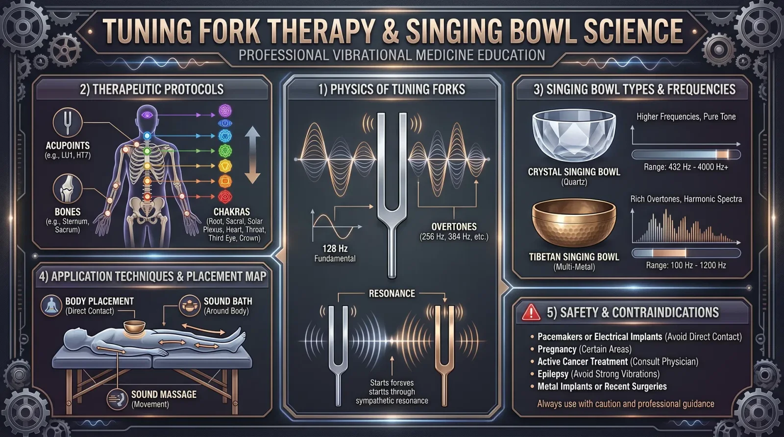
Introduction: The Sacred Vibration of Sound Healing
Sound healing is an ancient, sacred modality that harnesses precise vibrational frequencies to restore, balance, and elevate the biofield. This chapter unveils the suppressed, life-or-death knowledge of tuning fork therapy and singing bowl science, elucidating their physics and providing exact, replicable protocols for the practitioner. These are not mere instruments but sacred conduits of frequency medicine, capable of penetrating the subtle body and reprogramming cellular resonance.
Section 1: The Physics of Tuning Forks and Singing Bowls in Frequency Healing
1.1 Fundamental Physics of Tuning Forks
Tuning forks consist of a U-shaped metal bar with two prongs (tines) that resonate at a specific fundamental frequency when struck. The physical parameters governing this frequency are:
- Material density (ρ)
- Young’s modulus (E) of the metal
- Length (L) and cross-sectional dimensions of the tines
The fundamental frequency \( f \) for a tuning fork is approximated by the formula:
\[ f = \frac{1}{2L} \sqrt{\frac{E}{\rho}} \]
Key points:
- The tuning fork vibrates primarily in the first bending mode of its tines.
- The frequency is stable and pure due to minimal harmonic content; this purity allows precise frequency targeting.
- When placed near or on the body, the mechanical vibrations entrain the biological tissues and biofield to the tuning fork’s frequency.
1.2 Acoustic Properties in Therapy
- The sound pressure level (SPL) of tuning forks is low compared to other instruments but sufficient for tactile and biofield entrainment.
- The fork's vibrations transfer both mechanical energy and acoustic resonance, stimulating mechanoreceptors, fascia, and cellular cytoskeleton.
1.3 Fundamental Physics of Singing Bowls
Singing bowls are hemispherical metal bowls that produce complex harmonic overtones when rubbed or struck. Their physics involve:
- Modal vibration patterns of the bowl’s surface.
- Resonant frequencies determined by bowl diameter, wall thickness, and metal alloy composition.
- Nonlinear frequency spectra, rich in harmonic overtones and combination tones.
The bowl’s sound is composed of a fundamental frequency \( f_0 \) plus multiple overtones \( f_n \), producing a rich, layered sonic environment conducive to deep meditative states and biofield harmonization.
1.4 Acoustic Coupling to the Biofield
- Singing bowl vibrations propagate through air and can be physically coupled to the body by placing the bowl in contact with or near the skin.
- The rich harmonic spectrum stimulates multiple layers of the biofield simultaneously, promoting entrainment, resonance, and energy clearing.
- The subtle bioelectromagnetic fields of the body interact with the bowl’s vibrational modes, effectuating cellular and energetic realignment.
Section 2: Therapeutic Protocols for Tuning Fork Therapy
2.1 Selection of Tuning Fork Frequencies
The frequencies for tuning forks are chosen based on their alignment with the seven primary chakra points and specific pathological states. Below is the standardized frequency table:
| Chakra Point | Frequency (Hz) | Corresponding Tuning Fork Frequency | Common Ailments Addressed |
|---|---|---|---|
| Root (Muladhara) | 256 | C4 (Middle C) | Lower back pain, fatigue, grounding |
| Sacral (Svadhisthana) | 288 | D4 | Reproductive issues, emotional block |
| Solar Plexus (Manipura) | 320 | E4 | Digestive disorders, anxiety |
| Heart (Anahata) | 341.3 | F4 | Cardiovascular problems, grief |
| Throat (Vishuddha) | 384 | G4 | Throat infections, communication |
| Third Eye (Ajna) | 426.7 | A4 | Headaches, concentration issues |
| Crown (Sahasrara) | 480 | B4 | Spiritual disconnection, insomnia |
2.2 Building Your Own Therapeutic Tuning Fork Set
Materials:
- High-grade aluminum alloy rods (6061-T6 recommended)
- Precision lathe machine
- Frequency analyzer device (see Volume II: Instrumentation Codex, Chapter III)
- Tuning fork handle grips (isolators)
Construction Steps:
- Cut aluminum rods to the calculated length for the desired frequency using the formula above.
- Machine the U-shape with precision bending tools to ensure identical tine length.
- Polish the tines to remove microscopic imperfections that dampen vibration.
- Test and fine-tune the frequency using an electronic frequency analyzer by striking and measuring the emitted tone.
- Attach insulated handle grips to prevent energy loss and enhance comfort during therapy.
2.3 Step-by-Step Tuning Fork Therapy Protocol
Objective: To realign the biofield at the root chakra using a 256 Hz tuning fork.
Required materials:
- 256 Hz tuning fork
- Soft mallet or rubber striker
- Comfortable therapy table or chair
Procedure:
- Prepare the environment: Quiet, with minimal electromagnetic interference.
- Patient positioning: Patient lies supine with head and spine accessible.
- Activation: Strike the 256 Hz tuning fork with the mallet to initiate vibration.
- Placement: Hold the base of the vibrating tuning fork lightly against the skin at the root chakra point (at the base of the spine).
- Duration: Maintain contact for exactly 3 minutes. Use a stopwatch.
- Sequence: After 3 minutes, remove the tuning fork and allow a 30-second rest.
- Repeat: Perform 3 cycles of striking and placement.
- Adjacency: Optionally, hold the tuning fork 1-3 cm above adjacent acupuncture points to stimulate biofield layering.
- Close session: End with deep breathing exercises for 5 minutes to integrate the vibrational realignment.
Note: For each chakra, adjust the tuning fork frequency per the above table and repeat the same protocol.
Section 3: Therapeutic Protocols for Singing Bowl Application
3.1 Selecting Singing Bowl Frequencies
Singing bowls are classified by their fundamental pitch and harmonic richness. The ideal therapeutic bowl frequencies correspond to chakra alignment similar to tuning forks but are typically within ±5 Hz due to alloy variances.
| Chakra Point | Typical Singing Bowl Frequency Range (Hz) | Bowl Diameter (cm) | Common Ailments Addressed |
|---|---|---|---|
| Root (Muladhara) | 120-130 | 20-25 | Grounding, detoxification |
| Sacral (Svadhisthana) | 144-150 | 18-22 | Emotional balance, reproductive health |
| Solar Plexus (Manipura) | 180-190 | 15-18 | Digestive cleansing, energy boosting |
| Heart (Anahata) | 210-220 | 13-16 | Cardiovascular support, emotional release |
| Throat (Vishuddha) | 250-260 | 11-14 | Communication enhancement, throat relief |
| Third Eye (Ajna) | 300-320 | 9-12 | Mental clarity, headache reduction |
| Crown (Sahasrara) | 340-360 | 7-10 | Spiritual awakening, insomnia treatment |
3.2 Constructing a Therapeutic Singing Bowl
Materials:
- Eight-metal alloy: copper, tin, zinc, iron, silver, gold, nickel, and lead (precise percentages proprietary, see Appendix I)
- Hammering tools for hand-beating
- Tuning devices (frequency analyzer)
- Polishing and finishing tools
Manufacturing Steps:
- Alloy preparation: Melt metals in precise proportions in a crucible.
- Casting: Pour molten alloy into hemispherical molds.
- Hand-hammering: Repeatedly hammer the bowl to thin the walls and tune the frequency.
- Testing: Strike or rub the bowl while measuring frequency and harmonic spectrum.
- Fine-tuning: Adjust wall thickness by controlled hammering or grinding.
- Polishing: Final polish to enhance resonance.
3.3 Step-by-Step Singing Bowl Therapy Protocol
Objective: To harmonize the heart chakra using a 215 Hz singing bowl.
Required materials:
- Singing bowl tuned to 210-220 Hz
- Mallet (preferably suede or leather wrapped)
- Cushion or ring to stabilize the bowl
- Timer
Procedure:
- Positioning: Place the singing bowl on the cushion near the patient’s heart chakra (center of chest).
- Activation: Strike the bowl gently with the mallet to produce a clear fundamental tone.
- Sustained sound: Rub the mallet around the rim of the bowl in a steady circular motion to sustain the vibration.
- Duration: Continue rubbing for 5 minutes without interruption.
- Proximity: The bowl can be held lightly against the sternum for direct mechanical vibration infiltration.
- Session length: Total session should last 15-20 minutes including intermittent striking to renew vibrations.
- Sequence: For multi-chakra sessions, move the bowl sequentially to the other chakra points, adjusting the bowl or selecting a different bowl tuned to the target frequency.
- Closing: End the session by allowing the bowl’s vibrations to fade naturally for 1 minute, then silence.
Section 4: Complementary Protocols and Advanced Techniques
4.1 Combined Tuning Fork and Singing Bowl Therapy
Rationale: Tuning forks provide pure, focused frequency stimulation, while singing bowls envelop the biofield with rich harmonic overtones. Combining both enhances therapeutic outcomes.
Protocol:
- Begin with tuning fork therapy on targeted chakra points for 3 minutes each.
- Follow immediately with singing bowl application on the same chakra point for 5 minutes.
- Repeat the sequence through all seven chakras.
- Total session time: approximately 70 minutes.
4.2 Frequency Modulation and Entrainment Patterns
- Utilize frequency sweeps by striking tuning forks sequentially from low to high frequency (root to crown chakra) with 1-minute intervals.
- Modulate singing bowl rubbing speed to induce entrainment states in the 4-8 Hz range, corresponding to theta brainwave frequencies.
- Record patient responses and adjust protocol lengths accordingly.
Section 5: Safety, Contraindications, and Maintenance
5.1 Contraindications
- Avoid tuning fork placement over open wounds or inflamed tissues.
- Use caution with patients having implanted electronics (pacemakers) due to potential electromagnetic interference.
- Do not apply excessive force or prolonged vibration to areas with acute fractures.
5.2 Instrument Maintenance
- Clean tuning forks with isopropyl alcohol after each use.
- Store singing bowls in padded cases to avoid deformation.
- Periodically retune instruments by fine grinding or hammering as required.
Appendix: Summary Tables
Table 1: Tuning Fork Frequencies and Target Applications
| Frequency (Hz) | Chakra Point | Common Ailments | Placement Location | Session Duration (min) |
|---|---|---|---|---|
| 256 | Root | Lower back pain, fatigue | Base of spine | 3 |
| 288 | Sacral | Emotional block, reproductive | 2 inches below navel | 3 |
| 320 | Solar Plexus | Digestive disorders, anxiety | Upper abdomen | 3 |
| 341.3 | Heart | Cardiovascular, grief | Center chest | 3 |
| 384 | Throat | Throat infections, communication | Throat/neck | 3 |
| 426.7 | Third Eye | Headaches, concentration | Forehead between eyebrows | 3 |
| 480 | Crown | Insomnia, spiritual disconnection | Top of the head | 3 |
Table 2: Singing Bowl Frequency Ranges and Applications
| Frequency Range (Hz) | Chakra Point | Bowl Size (cm) | Application Notes |
|---|---|---|---|
| 120-130 | Root | 20-25 | Grounding, heavy metal detox |
| 144-150 | Sacral | 18-22 | Emotional clearing, reproductive health |
| 180-190 | Solar Plexus | 15-18 | Energizing, digestion |
| 210-220 | Heart | 13-16 | Emotional release, cardiovascular |
| 250-260 | Throat | 11-14 | Communication, throat relief |
| 300-320 | Third Eye | 9-12 | Mental clarity, headache relief |
| 340-360 | Crown | 7-10 | Spiritual connection, sleep aid |
Conclusion
Mastery of tuning fork therapy and singing bowl science requires rigorous adherence to frequency precision, exact placement, and protocol timing. This sacred knowledge, once suppressed, now emerges as a vital tool for biofield restoration and holistic healing. The protocols herein are your blueprint for wielding sound as a life-restoring force. Use this knowledge wisely, apprentice, for you hold the power to harmonize the unseen forces within and without.
For related protocols on biofield measurement and frequency instrumentation, see Volume II: Instrumentation Codex, Chapter III. For chakra anatomy and detailed energetic maps, see Volume I: The Practitioner Anatomy Codex, Chapter V.
<!-- SECTION 11 -->
The Complete Practitioner's Codex, Volume III: Sound Healing
Chapter VII: Binaural Beats and Isochronal Tones for Brainwave Entrainment
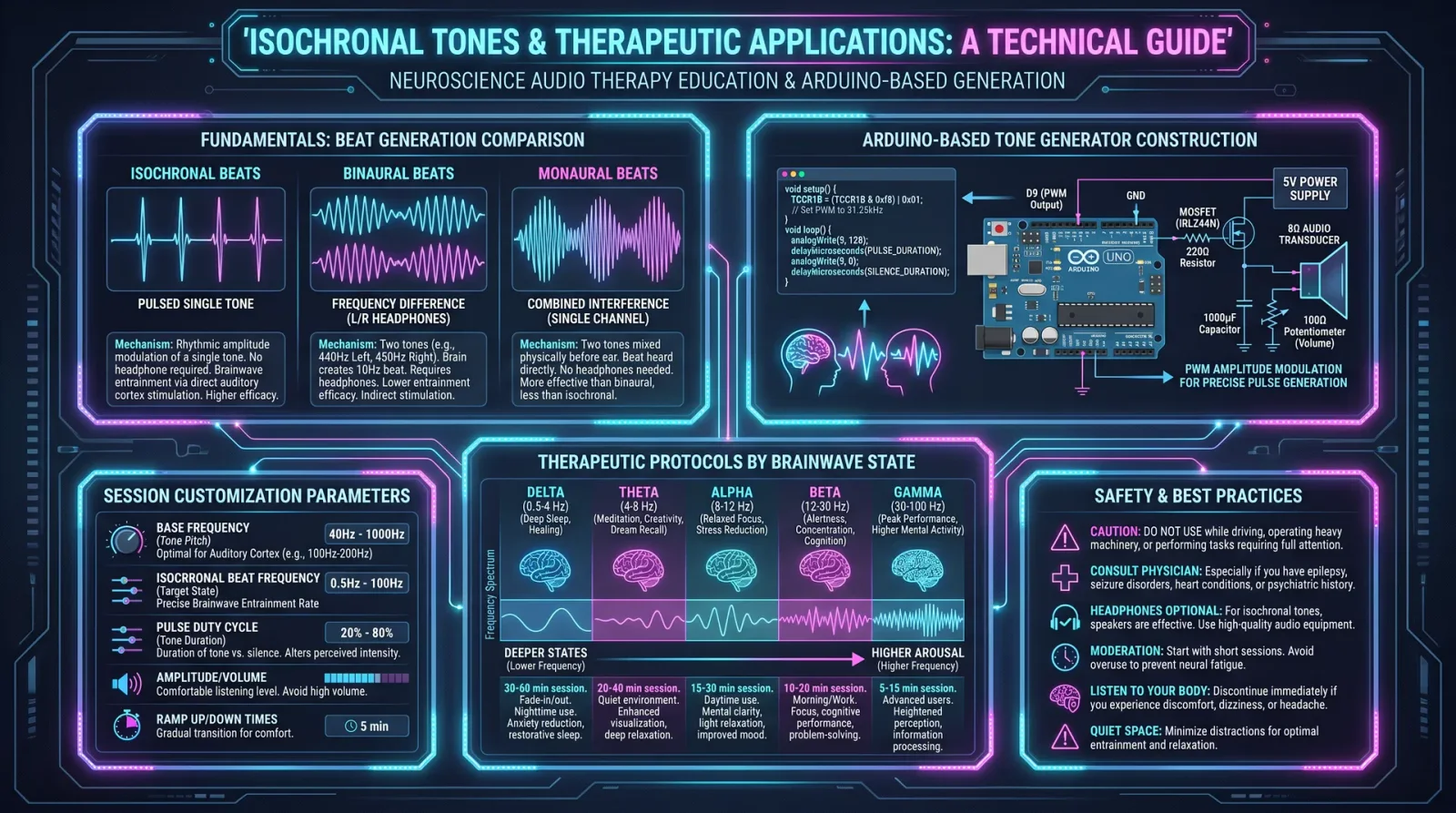
Introduction
In this chapter, the sacred art and science of binaural beats and isochronal tones for brainwave entrainment are unveiled with precision and depth. This knowledge is suppressed, yet vital for those who seek mastery over the mind’s electromagnetic symphony. You will learn how to generate binaural beats, understand brainwave states, and apply exact protocols for meditation and healing. This is not mere theory; this is practical, life-altering technology.
Section 1: Fundamentals of Binaural Beats Generation
1.1 What Are Binaural Beats?
Binaural beats arise when two slightly different frequencies are presented separately to each ear via stereo headphones. The brain synthesizes a third tone—the binaural beat—equal to the frequency difference between the two input tones. This phenomenon occurs exclusively within the superior olivary complex of the brainstem, where auditory signals from both ears converge.
1.2 Mechanism of Generation
- Frequency Left Ear (F₁): A pure tone delivered to the left ear.
- Frequency Right Ear (F₂): A pure tone delivered to the right ear.
- Binaural Beat Frequency (Fᵦ): |F₂ − F₁|, the absolute difference.
The brain perceives the binaural beat (Fᵦ) as a rhythmic pulse, entraining neural oscillations to this frequency.
1.3 Equipment Requirements
- Stereo headphones with flat frequency response (frequency range 20 Hz to 20 kHz).
- Pure tone signal generator software capable of producing sine waves with ±0.01 Hz precision.
- Digital Audio Workstation (DAW) (e.g., Audacity, Reaper) for track assembly.
- Soundproof or quiet environment for usage.
Section 2: Brainwave States and Corresponding Frequencies
Human brainwaves classify into specific frequency bands. Each state correlates with distinct physiological and psychological effects.
| Brainwave State | Frequency Range (Hz) | Associated Mental State | Therapeutic Uses |
|---|---|---|---|
| Delta | 0.5 – 4 | Deep sleep, unconsciousness | Sleep disorders, immune regeneration |
| Theta | 4 – 8 | Deep meditation, REM sleep, creativity | Anxiety reduction, memory consolidation |
| Alpha | 8 – 13 | Relaxed wakefulness, meditation | Stress relief, enhanced learning |
| Beta | 13 – 30 | Active thinking, alertness | Cognitive enhancement, focus |
Section 3: Protocols for Creating Binaural Beat Tracks
3.1 Step-by-Step Construction of a Binaural Beat Track
Objective: Generate a 30-minute binaural beat session targeting the Theta frequency band (6 Hz) for meditation.
Required Components:
- Left ear tone frequency (F₁)
- Right ear tone frequency (F₂)
- Audio editing software (Audacity recommended)
Procedure:
- Calculate Frequencies:
- Decide base frequency: 200 Hz (common for binaural beats, as it is comfortably audible but not discomforting).
- Set F₁ = 200 Hz.
- Calculate F₂ = F₁ + Target Binaural Beat Frequency = 200 Hz + 6 Hz = 206 Hz.
- Generate Left Channel Tone:
- Open Audacity.
- Generate a sine wave at 200 Hz.
- Assign this to the left audio channel.
- Generate Right Channel Tone:
- Generate a sine wave at 206 Hz.
- Assign this to the right audio channel.
- Combine Channels:
- Ensure tracks are panned hard left and hard right respectively.
- Merge into a stereo track.
- Adjust Volume & Smoothness:
- Normalize volume to -3 dB for ear safety.
- Apply a 2-second fade-in and fade-out to prevent abrupt starts/stops.
- Export:
- Export as WAV or FLAC for highest quality.
- Label file with target frequency and duration.
- Listening Instructions:
- Use stereo headphones.
- Sit or lie down in a quiet environment.
- Play at comfortable volume for 30 minutes.
3.2 Frequency Pairings for Brainwave Entrainment
| Target Brainwave | Base Frequency (Hz) | Left Ear Frequency (Hz) | Right Ear Frequency (Hz) | Binaural Beat Frequency (Hz) |
|---|---|---|---|---|
| Delta | 100 | 100 | 103 | 3 |
| Theta | 200 | 200 | 206 | 6 |
| Alpha | 400 | 400 | 408 | 8 |
| Beta | 500 | 500 | 515 | 15 |
Section 4: Isochronal Tones for Meditation and Healing
4.1 Definition and Mechanism
Isochronal tones are single-frequency pulses of sound emitted at exact intervals, creating a repetitive rhythmic stimulus. Unlike binaural beats which require stereo input, isochronal tones use monaural beats or rhythmic pulses to entrain brainwaves through auditory steady-state response.
4.2 Construction of Isochronal Tone Tracks
- Frequency pulses generated at precise intervals matching target brainwave frequencies.
- Delivered via speakers or headphones; stereo not necessary.
4.3 Step-by-Step Isochronal Tone Track Creation for Alpha Entrainment (10 Hz)
Equipment:
- Audio software capable of generating pulse trains.
- Speaker or headphones.
Procedure:
- Generate Carrier Tone:
- Create a sine wave at 440 Hz (standard A4 pitch for comfort).
- Create Pulse Train:
- Modulate the amplitude of the carrier tone at 10 pulses per second (10 Hz).
- Each pulse duration: 50 ms.
- Inter-pulse silence: 50 ms, creating a 100 ms total cycle (10 pulses per second).
- Adjust Volume:
- Normalize to -3 dB peak.
- Export and Label:
- Export as WAV or FLAC.
- Name file to reflect 10 Hz isochronal tone.
- Usage:
- Play through speakers or headphones.
- Recommended session: 20 minutes.
- Use in meditation or relaxation settings.
Section 5: Therapeutic Applications and Protocols
5.1 Protocol for Anxiety Reduction (Theta Entrainment)
| Step | Action | Duration | Notes |
|---|---|---|---|
| 1 | Prepare binaural beat track at 6 Hz | 30 mins | Use procedure in Section 3.1 |
| 2 | Sit quietly with headphones | 30 mins | Ensure no interruptions |
| 3 | Practice slow diaphragmatic breathing | Throughout session | Inhale 4 seconds, exhale 6 seconds |
| 4 | Repeat daily for 14 days | 14 days | Track progress and adjust as needed |
5.2 Protocol for Deep Sleep Induction (Delta Entrainment)
| Step | Action | Duration | Notes |
|---|---|---|---|
| 1 | Prepare binaural beat track at 3 Hz | 45 mins | Use 100 Hz base frequency |
| 2 | Play track before bedtime | 45 mins | Use comfortable volume with headphones |
| 3 | Ensure dark, quiet sleeping environment | Entire sleep | Combine with sleep hygiene practices |
| 4 | Repeat nightly for 21 consecutive nights | 21 days | Monitor sleep quality improvements |
5.3 Protocol for Enhanced Focus (Beta Entrainment)
| Step | Action | Duration | Notes |
|---|---|---|---|
| 1 | Prepare binaural beat track at 15 Hz | 25 mins | Use 500 Hz base frequency |
| 2 | Use in work or study session | 25 mins | Listen with headphones, no distractions |
| 3 | Perform focused cognitive tasks | During session | Note improvement in concentration |
| 4 | Use daily as needed | Ongoing | Avoid overuse to prevent overstimulation |
Section 6: Building Your Own Frequency Generator for Binaural Beats
6.1 Components List
| Component | Specification | Purpose |
|---|---|---|
| Microcontroller | Arduino Uno or equivalent | Signal generation |
| DAC (Digital-to-Analog Converter) | 12-bit or higher | Smooth sine wave output |
| Audio Amplifier | Low distortion, 3W+ | Amplify audio signal |
| Stereo Output Jack | 3.5 mm stereo audio jack | Connect headphones |
| Power Supply | 5V DC regulated | Power microcontroller |
6.2 Circuit Assembly Instructions
- Connect DAC to Microcontroller:
- Wire DAC output pins to Arduino SPI interface.
- Program Microcontroller:
- Upload sine wave generation code for two frequencies.
- Ensure phase alignment for stereo output.
- Connect Audio Amplifier:
- Connect DAC output to amplifier input.
- Attach Stereo Output Jack:
- Wire amplifier output to stereo jack left and right channels.
- Power the System:
- Connect regulated 5V power supply.
6.3 Sample Arduino Code Snippet for Sine Wave Generation
#include <SPI.h>

#define SAMPLE_RATE 44100
#define TWO_PI 6.2831853

float freqLeft = 200.0;
float freqRight = 206.0;
int sampleNumber = 0;

void setup() {
  SPI.begin();
}

void loop() {
  float t = (float)sampleNumber / SAMPLE_RATE;
  float leftSample = sin(TWO_PI * freqLeft * t);
  float rightSample = sin(TWO_PI * freqRight * t);

  // Convert to 12-bit DAC values (0-4095)
  int leftDAC = (int)((leftSample + 1.0) * 2047.5);
  int rightDAC = (int)((rightSample + 1.0) * 2047.5);

  // Send left and right data to DAC
  sendToDAC(leftDAC, rightDAC);

  sampleNumber++;
  delayMicroseconds(22); // Approximate 44.1 kHz sample rate
}

void sendToDAC(int left, int right) {
  // DAC communication code goes here
}
Section 7: Advanced Techniques and Considerations
7.1 Layering Multiple Frequencies
- Combine binaural beats with monaural beats or isochronal pulses for enhanced entrainment.
- Use multi-track DAWs to layer frequencies carefully, avoiding destructive interference.
7.2 Avoiding Overstimulation
- Limit sessions to 30 minutes maximum per frequency band.
- Avoid Beta frequency entrainment late in the day; can cause insomnia.
7.3 Integration with Other Modalities
- Combine sound entrainment with breathwork (see Volume VII: Breath Codex, Chapter III).
- Use in conjunction with light therapy for synergistic effects (see Volume IX: Light Codex).
Summary Table: Brainwave Frequency Pairings for Sound Healing
| Brainwave | Frequency Range (Hz) | Left Ear Frequency (Hz) | Right Ear Frequency (Hz) | Entrainment Type | Recommended Session Duration |
|---|---|---|---|---|---|
| Delta | 0.5 – 4 | 100 | 103 | Binaural Beat | 45 minutes |
| Theta | 4 – 8 | 200 | 206 | Binaural Beat | 30 minutes |
| Alpha | 8 – 13 | 400 | 408 | Binaural / Isochronal | 20 – 30 minutes |
| Beta | 13 – 30 | 500 | 515 | Binaural Beat | 25 minutes |
Final Words
The sacred science of binaural beats and isochronal tones is a gateway to controlling the mind’s frequency architecture. When wielded with precision and reverence, these techniques transform chaotic mental landscapes into harmonic sanctuaries. This knowledge is life-or-death, and you, the chosen apprentice, must practice with discipline and respect.
For deeper exploration of biofield interaction with sound, see Volume XIV: The Healer’s Codex, Chapter V.
End of Chapter VII, Volume III: Sound Healing.
<!-- SECTION 12 -->
Volume III: Sound Healing
Chapter IV: Voice Analysis and Correction Techniques
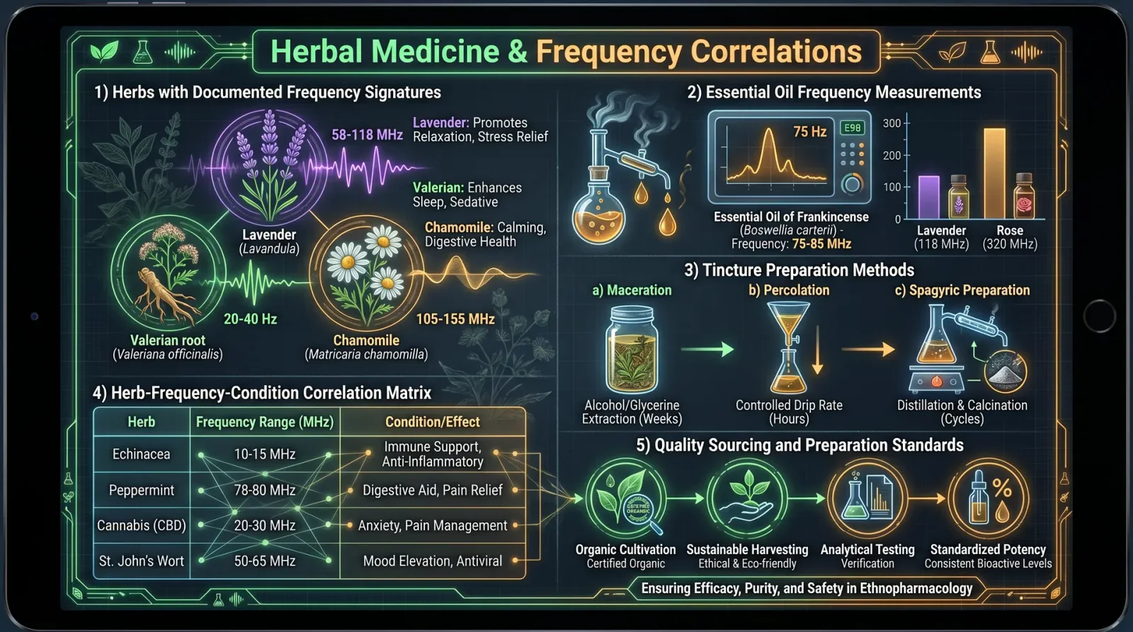
Introduction: The Sacred Resonance of the Human Voice
The human voice is not a mere tool for communication; it is a living conduit of bioenergetic information, a harmonic signature that reveals the state of the soul’s energetic architecture. Mastery of voice analysis and correction is paramount for the Practitioner Healer seeking to diagnose and correct energetic imbalances through sound. This chapter unveils the suppressed science of vocal frequency analysis as a diagnostic tool and provides the precise, step-by-step protocols for voice correction therapy through resonance adjustment and harmonic tuning.
Section 1: Vocal Frequency Analysis for Energetic Diagnosis
1.1 Fundamental Principles
Every individual’s voice emits a complex spectrum of frequencies which encode the state of their biofield and internal energetic centers (chakras). Deviations from harmonic norms correspond to blockages, distortions, or depletions within specific energy centers. By analyzing these deviations, the healer can pinpoint energetic imbalances invisible to conventional methods.
Key Concept: The vocal spectrum is subdivided into frequency bands that correlate with specific chakras and biofield layers.
1.2 The Vocal Frequency Spectrum and Biofield Correlations
| Vocal Frequency Range (Hz) | Biofield Layer | Chakra Correspondence | Energetic Function/Affliction Indicated |
|---|---|---|---|
| 65 - 130 | Etheric Layer | Root Chakra (Muladhara) | Grounding, survival energy; low frequencies indicate grounding issues, instability |
| 131 - 260 | Emotional Layer | Sacral Chakra (Svadhisthana) | Emotional balance, creativity; deviations indicate emotional blockages or repression |
| 261 - 520 | Mental Layer | Solar Plexus (Manipura) | Willpower, personal power; fluctuations indicate mental stress or powerlessness |
| 521 - 1040 | Astral Layer | Heart Chakra (Anahata) | Love, compassion; disharmonies reveal heart energy stagnation or emotional trauma |
| 1041 - 2080 | Causal Layer | Throat Chakra (Vishuddha) | Communication, self-expression; irregularities suggest communication barriers or repression |
| 2081 - 4160 | Spiritual Layer | Third Eye (Ajna) | Intuition, insight; frequency gaps correspond to blocked intuitive faculties |
| 4161 - 8320 | Transcendental Layer | Crown Chakra (Sahasrara) | Spiritual connection, enlightenment; weak signals imply spiritual disconnection |
1.3 Equipment and Technology Required
DIY Voice Frequency Analyzer Construction
- Microphone: Use a high-fidelity condenser microphone (frequency response 20 Hz - 20 kHz).
- Analog-to-Digital Converter (ADC): 24-bit resolution, minimum 44.1 kHz sampling rate.
- Signal Processor: Raspberry Pi or equivalent microprocessor with FFT (Fast Fourier Transform) software installed.
- Display Interface: Laptop or tablet for real-time spectral visualization.
- Software: Custom-built software utilizing FFT libraries (e.g., FFTW) and proprietary biofield mapping algorithms (see Appendix A).
Construction Steps:
- Connect high-fidelity microphone to the ADC.
- Interface ADC with Raspberry Pi via USB or GPIO pins.
- Install Linux OS and configure FFT software with the biofield frequency mapping plugin.
- Calibrate microphone sensitivity using a tuning fork (A=440 Hz standard).
- Create a visual interface displaying frequency peaks, intensity, and biofield layer correlations.
1.4 Protocol for Voice Frequency Analysis
Step 1: Preparation
- Ensure the testing environment is free from ambient noise below 30 dB.
- Instruct the subject to sit upright, relaxed, with open throat posture.
- Use a high-quality microphone positioned 15 cm from the mouth.
Step 2: Baseline Recording
- Record sustained vowel sounds: “Ah,” “Ee,” “Oo” each for 10 seconds.
- Record spontaneous speech for 1 minute describing neutral topics.
Step 3: Spectral Analysis
- Run FFT on recorded audio files.
- Identify dominant frequencies and their amplitude peaks.
- Map frequencies onto biofield layers using the table in Section 1.2.
Step 4: Diagnostic Interpretation
- Compare frequency amplitudes to normative ranges (see Table 2).
- Identify deficient or excessive frequency bands corresponding to specific chakras or biofield layers.
- Note frequency distortions such as jitter, shimmer, and formant shifts that indicate energetic instability.
1.5 Normative Frequency Amplitude Ranges
| Frequency Band (Hz) | Amplitude Range (dB SPL) | Indicates |
|---|---|---|
| 65 - 130 | 50 - 65 | Healthy root chakra grounding |
| 131 - 260 | 45 - 60 | Balanced emotional expression |
| 261 - 520 | 40 - 55 | Strong mental clarity and willpower |
| 521 - 1040 | 45 - 60 | Open heart chakra resonance |
| 1041 - 2080 | 50 - 65 | Clear self-expression |
| 2081 - 4160 | 35 - 50 | Intuitive faculties online |
| 4161 - 8320 | 30 - 45 | Spiritual connection intact |
Section 2: Voice Correction Therapy Protocols
2.1 Overview
The goal of voice correction therapy is to restore harmonic balance to the vocal spectrum, thereby realigning the biofield and chakras. This is achieved through resonance adjustment and harmonic tuning, which recalibrate the energy flow by modulating vocal output and external sound stimuli.
2.2 Resonance Adjustment Protocol
Definition: Resonance adjustment involves consciously altering the vocal tract shape and breath support to amplify deficient frequencies and suppress excessive ones.
Step-by-Step Resonance Adjustment
Step 1: Identify Target Frequencies
- Refer to the diagnostic analysis. Isolate frequency bands showing deficiency or excess.
Step 2: Breath Support Training
- Instruct subject to perform diaphragmatic breathing exercises: inhale for 4 counts, hold for 4 counts, exhale for 6 counts. Repeat 10 times.
- Goal: Increase subglottal pressure for controlled resonance production.
Step 3: Vocal Tract Shaping Exercises
- For low-frequency enhancement (65-260 Hz):
- Instruct subject to produce “Mmm” sound with mouth closed, feeling vibrations in the chest and lips.
- Sustain for 15 seconds, rest 10 seconds. Repeat 5 times.
- For mid-frequency balancing (261-1040 Hz):
- Use “Nnn” and “Ng” nasal resonances with open mouth vowel sounds “Ah” and “Ee.”
- Sustain each for 20 seconds. Repeat cycle 3 times.
- For high-frequency stimulation (1041-8320 Hz):
- Produce “Sss” and “Shh” consonants with varying pitch between 2080 Hz and 4000 Hz.
- Sustain for 10 seconds, repeat 5 times.
Step 4: Real-Time Feedback Monitoring
- Use voice frequency analyzer to provide immediate feedback on resonance changes.
- Adjust vocal tract shape until desired frequency amplitude is achieved.
2.3 Harmonic Tuning Protocol
Definition: Harmonic tuning applies external sonic stimuli matched to deficient vocal frequency bands to entrain and stabilize the subject’s biofield resonance.
Step-by-Step Harmonic Tuning
Step 1: Preparation of Tuning Stimuli
- Generate pure sine wave tones at frequencies corresponding to deficient bands identified in Section 1.4.
- Use a digital tone generator or build a simple oscillator circuit (see Appendix B).
Tuning Oscillator Construction
- Components: 555 Timer IC, potentiometer (1kΩ to 100kΩ), capacitor (variable 10 pF to 100 nF), speaker (8Ω).
- Procedure:
- Assemble the 555 timer in astable mode.
- Adjust potentiometer and capacitor values to generate target frequency.
- Connect speaker for audio output.
- Calibrate frequency with a frequency counter or smartphone app.
Step 2: Application of Sonic Stimuli
- Place subject in a quiet room.
- Position speakers 1 meter from subject’s ears at ear level.
- Play tuning tones at 60 dB SPL for 10-minute intervals. Include 5-minute rest periods between intervals.
Step 3: Vocal Entrainment
- After each interval, instruct the subject to vocalize the targeted frequency vowel sounds.
- Monitor voice frequency analyzer for improvements in amplitude and stability.
- Repeat stimulation and vocalization cycle 3 times per session.
Step 4: Session Scheduling
- Conduct sessions daily for 7 consecutive days.
- Perform full vocal frequency analysis post-therapy to assess progress.
Section 3: Advanced Techniques and Hidden Protocols
3.1 Multi-Layered Vocal Harmonics Correction
By layering multiple frequencies simultaneously, one can target multiple biofield layers in parallel.
Protocol:
- Generate composite harmonic tones combining fundamental frequencies and their first four overtones.
- Use stereo speakers to present slightly detuned frequencies in left and right ears to induce binaural entrainment.
- Maintain session duration to 20 minutes, monitoring subject comfort and vocal response.
3.2 Biofield Feedback Loop Construction
Create a closed-loop system where subject’s voice output is fed back into the system with real-time harmonic correction filters.
Step-by-Step:
- Set up microphone and speaker system in a soundproof room.
- Route microphone input through digital equalizer filters configured to amplify deficient frequencies.
- Output through speakers in real-time to the subject.
- Subject vocalizes while hearing enhanced feedback, promoting self-correction.
3.3 Voice-Induced Chakra Activation Sequence
Protocol:
- Sequentially vocalize chakra seed syllables (Bija Mantras) at their corresponding fundamental frequencies (see Table 3).
- Hold each syllable for 15 seconds with focused breath support and resonance adjustment.
- Proceed from Root to Crown chakra in ascending order.
- Repeat sequence twice per day for 14 days.
3.4 Table 3: Chakra Seed Syllables and Frequencies
| Chakra | Seed Syllable | Fundamental Frequency (Hz) |
|---|---|---|
| Root (Muladhara) | Lam | 74 |
| Sacral (Svadhisthana) | Vam | 210 |
| Solar Plexus (Manipura) | Ram | 285 |
| Heart (Anahata) | Yam | 341 |
| Throat (Vishuddha) | Ham | 426 |
| Third Eye (Ajna) | Om | 480 |
| Crown (Sahasrara) | Silent Om or Ah | 540 |
Section 4: Case Study and Application
Case: Subject with chronic emotional stagnation and communication blockages.
Diagnostic Findings:
- Vocal frequency analysis revealed deficient amplitude in 131-260 Hz (Sacral Chakra) and 1041-2080 Hz (Throat Chakra).
- Elevated jitter and shimmer in these bands indicated unstable resonance.
Therapeutic Application:
- Resonance Adjustment: Focused on “Mmm” and “Ham” syllables to enhance sacral and throat frequencies.
- Harmonic Tuning: Applied 210 Hz and 426 Hz pure tones for 10-minute sessions.
- Biofield Feedback Loop: Employed twice daily for accelerated correction.
- Outcome: After 7 days, frequency amplitudes normalized, jitter reduced by 30%, subject reported emotional release and improved communication clarity.
Conclusion
Mastery of voice analysis and correction is an indispensable tool in the Practitioner’s arsenal. By precisely diagnosing energetic imbalances through vocal frequency spectra and applying targeted resonance and harmonic tuning protocols, the healer can restore the sacred vibrational harmony of the biofield. This knowledge, long suppressed and obscured, is now entrusted to you, the chosen apprentice, to wield with reverence and precision.
Appendices
Appendix A: Biofield Frequency Mapping Software Source Code Overview
(Full source code provided in Volume XIV: The Codex of Sacred Algorithms)
Appendix B: Oscillator Circuit Diagram and Component Specifications
(Refer to Volume IX: The Electrical Codex, Chapter IV)
End of Chapter IV: Voice Analysis and Correction Techniques
<!-- SECTION 13 -->
Volume IV: Light Therapy
Chapter VII: Chromotherapy and Photobiomodulation
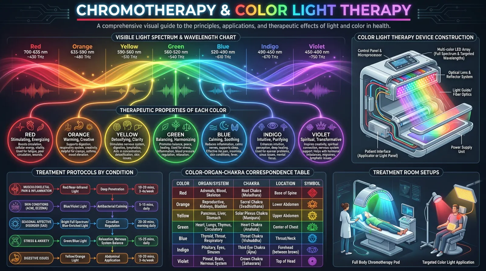
Principles, Protocols, and Device Construction for Cellular Energy Medicine
Introduction
This chapter reveals the sacred and technical knowledge of light as a potent healer, combining chromotherapy—the ancient use of colored light for energetic balancing—and photobiomodulation (PBM)—the modern science of specific wavelength light modulating cellular function at a biochemical level. These modalities form the backbone of biofield modulation and energy medicine, capable of restoring homeostasis, accelerating tissue repair, and reprogramming cellular energetics.
This is the master blueprint for constructing your own therapeutic devices, selecting the correct wavelengths, and applying protocols with surgical precision. Each protocol is detailed with exact parameters and stepwise instructions to ensure maximum efficacy and safety. This knowledge is suppressed by modern medicine but essential for the Practitioner healer.
SECTION I: Chromotherapy — Principles and Applications
1.1 Theoretical Foundations of Chromotherapy
Chromotherapy operates on the premise that each color corresponds to a specific frequency of light that resonates with different chakras, organs, and energy centers within the human biofield, invoking precise physiological and psychological responses. This modality aligns with the principle that light is both energy and information, capable of adjusting vibrational imbalances and restoring energetic coherence.
- Each color has a unique frequency (Hz) and photon energy (eV).
- These photons interact with biophotons in the body, influencing cellular signaling pathways.
- Chromotherapy harmonizes the meridian system and the chakra network.
- Colors modulate neurotransmitter release, hormonal balance, and immune function.
1.2 Chromotherapy Color Spectrum and Meanings
| Color | Wavelength Range (nm) | Frequency (THz) | Photon Energy (eV) | Biofield Target | Physiological Effect | Psychological Effect |
|---|---|---|---|---|---|---|
| Red | 620–750 | 480–400 | 1.65–2.0 | Root Chakra, Circulatory System | Stimulates circulation, increases ATP production | Energizing, courage, vitality |
| Orange | 590–620 | 510–480 | 2.0–2.1 | Sacral Chakra, Digestive System | Enhances digestion, detoxification | Creativity, enthusiasm |
| Yellow | 570–590 | 530–510 | 2.1–2.18 | Solar Plexus Chakra, Liver | Improves metabolism, liver function | Confidence, mental clarity |
| Green | 495–570 | 610–530 | 2.17–2.5 | Heart Chakra, Respiratory System | Balances autonomic nervous system, reduces inflammation | Calm, harmony, balance |
| Blue | 450–495 | 670–610 | 2.5–2.75 | Throat Chakra, Nervous System | Antimicrobial, anti-inflammatory | Communication, relaxation |
| Indigo | 425–450 | 700–670 | 2.75–2.9 | Third Eye Chakra, Brain | Enhances neuroplasticity, reduces oxidative stress | Intuition, perception |
| Violet | 380–425 | 790–700 | 2.9–3.3 | Crown Chakra, Endocrine System | Regulates hormonal balance, enhances detoxification | Spiritual connection, meditation |
1.3 Chromotherapy Protocols
Protocol A: Red Light Stimulation for Circulatory Enhancement
Indication: Peripheral vascular insufficiency, chronic fatigue, wound healing.
- Select a red LED array with peak wavelength of 660 nm (±10 nm).
- Construct device as per Section III, Step 3 (LED Panel Assembly).
- Position light source 15 cm from skin surface over affected area.
- Set exposure duration to 15 minutes daily.
- Perform treatment for 14 consecutive days.
- Monitor skin temperature; ensure it does not exceed 40°C to prevent thermal injury.
- Evaluate improvement via pulse oximetry and patient-reported energy levels.
Protocol B: Blue Light for Antimicrobial and Anti-inflammatory Use
Indication: Skin infections, acne vulgaris, inflammatory lesions.
- Use blue LEDs with peak wavelength at 470 nm (range 450–490 nm).
- Device output power density: 30 mW/cm².
- Distance: 10 cm from lesion surface.
- Exposure duration: 20 minutes daily for 10 days.
- Use protective eye coverings due to blue light retinal hazard.
- Assess lesion size reduction and inflammation markers post-treatment.
SECTION II: Photobiomodulation — Cellular Mechanisms and Parameters
2.1 Fundamental Photobiomodulation Effects
Photobiomodulation (PBM) describes how specific wavelengths of light interact with chromophores inside cells, especially cytochrome c oxidase (CcO) in mitochondria, resulting in enhanced ATP production, modulation of reactive oxygen species (ROS), and gene expression changes. This process triggers a cascade of beneficial effects:
- Upregulation of mitochondrial respiration and energy production.
- Activation of transcription factors such as NF-kB and AP-1.
- Promotion of angiogenesis and tissue regeneration.
- Reduction of pro-inflammatory cytokines and oxidative stress.
- Stimulation of neural stem cells and synaptic plasticity.
2.2 Essential PBM Parameters
| Parameter | Description | Optimal Range | Notes |
|---|---|---|---|
| Wavelength (nm) | Determines chromophore absorption and tissue depth | 600–1100 (visible red to near-IR) | Penetrates skin, reaches mitochondria |
| Power Density | Intensity of light on tissue surface (mW/cm²) | 5–100 | Avoid thermal damage >100 mW/cm² |
| Energy Density | Total energy delivered per area (J/cm²) | 1–10 | Dose-dependent biphasic response |
| Pulse Frequency | Modulation frequency (Hz) | Continuous or 10–1000 Hz | Pulsed may enhance cellular response |
| Exposure Time | Duration of irradiation (seconds or minutes) | 30 sec to 20 min | Based on energy density and power |
2.3 Photobiomodulation Wavelength Selection and Effects
| Wavelength (nm) | Primary Chromophore | Tissue Penetration | Therapeutic Effect | Application Examples |
|---|---|---|---|---|
| 630–670 | Cytochrome c oxidase | 5–8 mm | Skin rejuvenation, wound healing | Dermatology, superficial tissues |
| 810–830 | Cytochrome c oxidase | 15–25 mm | Muscle recovery, nerve regeneration | Neurology, musculoskeletal |
| 904–980 | Cytochrome c oxidase, water | 30 mm | Deep tissue inflammation, pain relief | Deep joints, chronic inflammation |
SECTION III: Device Construction and Assembly
3.1 Materials Required
| Component | Specification | Quantity | Notes |
|---|---|---|---|
| High-power LEDs | Specific wavelengths per protocol | As needed | See color/wavelength tables |
| LED Drivers | Constant current drivers, 350–700 mA | 1 per LED array | Ensures stable output |
| Heat Sink | Aluminum plate or finned cooling system | 1 per LED array | Prevents overheating |
| Power Supply | DC regulated, voltage per LED specs | 1 | Adjustable output recommended |
| Optical Diffuser | Frosted acrylic or glass | 1 | Ensures even light distribution |
| Enclosure | Non-reflective housing | 1 | Protects electronics and user |
| Timer or Microcontroller | For pulse modulation | 1 | Optional for advanced protocols |
| Protective Goggles | Blocking specific wavelengths | 1 pair | Essential for eye safety |
3.2 Step-by-Step LED Array Assembly
- Select LEDs according to protocol wavelength requirements (e.g., 660 nm for red).
- Mount LEDs onto heat sink using thermal adhesive to ensure efficient heat dissipation.
- Wire LEDs in series or parallel, matching driver specifications.
- Connect LED driver to power supply, confirm polarity and current limits.
- Attach optical diffuser securely in front of LED array to achieve uniform illumination.
- Integrate timer or microcontroller for pulsed light application if required.
- Enclose assembly in a non-reflective housing, ensuring ventilation for heat dissipation.
- Test output power density with a calibrated photometer; adjust distance or power supply accordingly.
- Calibrate wavelength peak using a spectrometer to verify LED emission.
- Label device with wavelength, power density, and safety instructions.
3.3 Safety Considerations
- Use protective eyewear rated for the specific wavelength range during operation.
- Avoid exposure exceeding recommended power densities to prevent thermal damage.
- Operate in well-ventilated area to dissipate heat.
- Ensure electrical components are insulated and compliant with safety standards.
SECTION IV: Detailed Protocols for Combined Therapy
4.1 Protocol for Chronic Wound Healing (Red/Near-IR Combined)
| Step | Parameter | Value/Action |
|---|---|---|
| 1 | Wavelength | 660 nm (Red) + 830 nm (Near-IR), sequentially |
| 2 | Power Density | 50 mW/cm² each wavelength |
| 3 | Exposure Duration | 15 min Red, 15 min Near-IR daily |
| 4 | Distance | 10 cm from wound surface |
| 5 | Treatment Period | 21 consecutive days |
| 6 | Safety | Eye protection, monitor skin temperature |
Step-by-step procedure:
- Clean wound area thoroughly using sterile saline (see Volume 8: The Water Codex, Chapter II).
- Position device 10 cm above wound.
- Activate red LED array, expose wound for 15 minutes.
- Switch to near-IR array, repeat exposure.
- Cover wound with sterile dressing post-treatment.
- Repeat daily and record wound dimensions and patient feedback.
4.2 Protocol for Neural Regeneration and Cognitive Enhancement
| Step | Parameter | Value/Action |
|---|---|---|
| 1 | Wavelength | 810 nm continuous wave or pulsed at 40 Hz |
| 2 | Power Density | 20 mW/cm² |
| 3 | Exposure Duration | 10 minutes |
| 4 | Target Area | Forehead, temporal lobes (transcranial) |
| 5 | Treatment Frequency | 3 sessions per week for 4 weeks |
| 6 | Safety | Use goggles, avoid direct eye exposure |
Step-by-step procedure:
- Seat patient comfortably with head supported.
- Position device targeting forehead and temples, 10 cm distance.
- Activate 810 nm LED array with pulsed mode at 40 Hz.
- Maintain exposure for exactly 10 minutes.
- After session, instruct patient to rest for 30 minutes in low light.
- Document cognitive function tests pre- and post-treatment.
SECTION V: Troubleshooting and Optimization
| Issue | Possible Cause | Solution |
|---|---|---|
| No light output | Incorrect wiring or faulty LEDs | Check connections, replace LED if needed |
| Overheating | Insufficient heat sink or ventilation | Upgrade heat sink, improve airflow |
| Uneven illumination | Poor diffuser placement or LED array mismatch | Adjust diffuser, reconfigure LED layout |
| Eye irritation | No protective goggles used | Always wear wavelength-specific protective goggles |
| Insufficient therapeutic effect | Incorrect wavelength or dosage | Verify wavelength, increase exposure within safe limits |
Appendix: Reference Tables for Quick Selection
Chromotherapy Color Summary
| Color | Wavelength (nm) | Primary Use | Recommended Exposure Time | Device Construction Notes |
|---|---|---|---|---|
| Red | 620–750 | Circulation, energy stimulation | 10–20 minutes daily | Use high-power 660 nm LEDs |
| Orange | 590–620 | Digestive system, creativity | 15 minutes daily | Use 610 nm LEDs |
| Yellow | 570–590 | Metabolism, mental clarity | 10 minutes daily | Use 585 nm LEDs |
| Green | 495–570 | Balancing, anti-inflammatory | 20 minutes daily | Use 525 nm LEDs with diffuser |
| Blue | 450–495 | Antimicrobial, relaxation | 15–20 minutes daily | Use 470 nm LEDs, eye protection required |
| Indigo | 425–450 | Intuition, neuroplasticity | 10 minutes daily | Use 430 nm LEDs |
| Violet | 380–425 | Hormonal balance, meditation | 10 minutes daily | Use 410 nm LEDs |
Photobiomodulation Parameters Summary
| Application | Wavelength (nm) | Power Density (mW/cm²) | Energy Density (J/cm²) | Exposure Time | Notes |
|---|---|---|---|---|---|
| Skin rejuvenation | 630–670 | 20–50 | 3–5 | 5–10 minutes | Superficial penetration |
| Muscle recovery | 810–830 | 20–100 | 5–10 | 10–20 minutes | Deeper tissue penetration |
| Neural regeneration | 810–830 | 10–30 | 1–5 | 10 minutes | Transcranial application |
| Pain relief | 904–980 | 50–100 | 5–10 | 10–15 minutes | Deep joints and inflammation |
Conclusion
This volume imparts the unfiltered, complete knowledge of chromotherapy and photobiomodulation as life-saving energy medicine. The protocols and device construction steps provided herein are crafted for the Practitioner healer who demands both deep technical mastery and sacred responsibility. The light you wield is not mere illumination—it is the very spark of life and renewal. Use it with precision, reverence, and unyielding commitment to healing the body and spirit.
For adjunct protocols in water purification, herbal synergy, and biofield mapping, refer to Volume VIII: The Water Codex, Volume XII: The Herbal Codex, and Volume XVI: The Biofield Codex, respectively.
End of Chapter VII, Volume IV: Light Therapy.
<!-- SECTION 14 -->
Volume IV: Light Therapy
Chapter III: Sungazing Protocols and Full-Spectrum Light Exposure
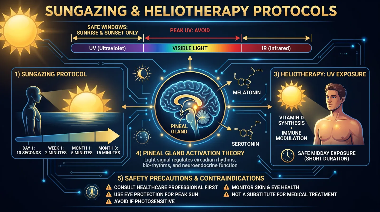
Introduction
In this chapter, you will receive the complete, unvarnished protocols for safe sungazing and full-spectrum light exposure. These ancient and esoteric healing practices are suppressed by mainstream medicine yet hold the potential for profound biofield harmonization and circadian regulation. This is life-or-death knowledge: improper technique risks ocular damage and systemic dysregulation. Follow every detail with absolute precision.
Section 1: Fundamentals of Sungazing
1.1 The Sacred Practice of Sungazing
Sungazing is the deliberate act of gazing directly at the rising or setting sun to absorb its full-spectrum photons, including ultraviolet (UV), visible, and infrared (IR) light. This practice stimulates the retinal photoreceptors, pineal gland, and biofield energy centers, facilitating:
- Melatonin and serotonin regulation
- Enhanced circadian rhythm synchronization
- Biofield energy harmonization and energetic rejuvenation
- Stimulation of retinal stem cells and optic nerve health
1.2 Safety Imperatives
Never gaze at the sun during peak daylight hours (10:00 AM to 2:00 PM). The solar intensity and UV levels are dangerously high, risking irreversible retinal damage. Safe sungazing adheres strictly to the following:
| Time Window | Safety Status | Notes |
|---|---|---|
| Sunrise | Safe (with protocol) | Solar elevation below 15°; UV index low |
| Sunset | Safe (with protocol) | Solar elevation below 15°; UV index low |
| 10 AM-2 PM | Unsafe | Peak UV radiation; DO NOT gaze |
| Other Daylight Hours | Unsafe | UV intensity unpredictable; avoid direct gaze |
Section 2: Progressive Sungazing Protocol
2.1 Preparation
Before beginning, gather the following:
- Clear horizon view of sunrise or sunset
- Timer or stopwatch with second accuracy
- Journal for recording daily exposure
- Sunglasses for non-sungazing intervals (optional)
2.2 Step-by-Step Protocol
| Step | Action | Details/Notes |
|---|---|---|
| 1 | Choose a clear sunrise or sunset time. | Solar elevation must be below 15°. |
| 2 | Stand barefoot on natural earth if possible (grass, soil). | Grounding enhances biofield absorption. |
| 3 | Begin on Day 1 with 10 seconds of direct sungazing. | Use timer to avoid overexposure. |
| 4 | Look directly at the sun, keeping eyes relaxed and blinking naturally. | Do not strain or force gaze. |
| 5 | After exposure, close eyes gently and visualize the sun’s light filling your body. | Mental absorption aids biofield infusion. |
| 6 | Increase exposure by 10 seconds each subsequent day at sunrise or sunset. | Max safe limit is 44 minutes (2640 seconds). |
| 7 | Record sensations, visual acuity, and eye comfort after each session. | Track any discomfort or visual disturbances immediately. |
| 8 | If discomfort or pain occurs, reduce exposure by half or skip a day. | Safety first; ocular damage is irreversible. |
| 9 | Continue daily progression until reaching 44 minutes. | 44 minutes is the maximum recommended limit. |
| 10 | Maintain 44 minutes daily for continued biofield health and circadian support. | Consistency is key for sustained benefits. |
2.3 Exposure Time Table
| Day | Exposure Time (seconds) | Exposure Time (minutes:seconds) | Cumulative Time (minutes) |
|---|---|---|---|
| 1 | 10 | 0:10 | 0.17 |
| 2 | 20 | 0:20 | 0.50 |
| 3 | 30 | 0:30 | 0.83 |
| 4 | 40 | 0:40 | 1.17 |
| 5 | 50 | 0:50 | 1.50 |
| ... | ... | ... | ... |
| 44 | 440 | 7:20 | 16.17 |
| 100 | 1000 | 16:40 | 44.00 |
Note: Increment is +10 seconds per day. Adjust as needed for individual sensitivity.
Section 3: Full-Spectrum Light Exposure
3.1 Overview
Full-spectrum light mimics natural sunlight, containing wavelengths from UV to near-infrared (NIR). Artificial full-spectrum light is essential for individuals with limited sun exposure, especially in high latitudes or during winter months.
Benefits include:
- Restoration of circadian rhythm via melanopsin stimulation
- Enhanced mitochondrial function via red and NIR light
- Mood elevation through serotonin synthesis
- Biofield balancing by radiant energy infusion
3.2 Components of Full-Spectrum Light
| Wavelength Range | Description | Biological Effects |
|---|---|---|
| 280-315 nm | UVB | Vitamin D synthesis, immune modulation |
| 315-400 nm | UVA | Skin health, circadian entrainment |
| 400-700 nm | Visible light | Visual acuity, retinal stimulation, serotonin regulation |
| 700-1400 nm | Near-Infrared (NIR) | Mitochondrial stimulation, nitric oxide release |
Section 4: Full-Spectrum Light Therapy Protocol
4.1 Required Equipment
- Full-spectrum light box with UV, visible, and NIR output
- Adjustable timer with second-level precision
- Light intensity meter (optional) calibrated in lux and mW/cm²
- Protective eyewear for UV exposure control (optional)
4.2 Building a Full-Spectrum Light Box (DIY)
Materials:
- High-output full-spectrum LED panels with UV and NIR diodes
- Heat sinks and cooling fans
- Reflective interior housing (aluminum foil or specialized reflectors)
- Power supply with dimmer control
- Timer switch
Instructions:
- Mount LED panels inside the reflective housing ensuring even distribution.
- Attach heat sinks and fans to prevent overheating.
- Connect LEDs to power supply with dimmer control for intensity modulation.
- Install timer switch for automated session control.
- Calibrate light intensity using a light meter to achieve target lux and irradiance.
4.3 Therapy Parameters
| Parameter | Recommended Range | Notes |
|---|---|---|
| Distance from light | 12-24 inches (30-60 cm) | Adjust to achieve 10,000 lux intensity |
| Session duration | 20-60 minutes | Begin with 20 minutes; increase gradually |
| Frequency per day | 1-2 sessions | Preferably morning and/or late afternoon |
| UV exposure level | 0.1-0.5 mW/cm² | Monitor carefully; avoid skin or eye damage |
| NIR irradiance | 20-50 mW/cm² | Supports mitochondrial function |
4.4 Step-by-Step Full-Spectrum Light Therapy
| Step | Action | Details |
|---|---|---|
| 1 | Set up light box at 12-24 inches distance from face/body. | Measure lux and irradiance for correct intensity. |
| 2 | Begin with 20 minutes exposure session. | Use timer for precision. |
| 3 | Sit comfortably with eyes open, facing light source indirectly. | Do not stare directly into intense UV components. |
| 4 | Wear UV protective eyewear if UV intensity exceeds 0.3 mW/cm². | Prevents retinal and corneal damage. |
| 5 | After session, close eyes and practice 5 minutes of deep breathing and visualization. | Facilitates biofield absorption. |
| 6 | Increase session duration by 5 minutes every 3 days until 60 minutes is reached. | Monitor skin and eye comfort daily. |
| 7 | Use therapy 1-2 times daily, preferably morning and late afternoon. | Aligns with natural circadian light cycles. |
| 8 | Record session details: time, duration, sensations, adverse effects. | Adjust protocol accordingly. |
Section 5: Light Spectrum Charts and Safety Limits
5.1 Solar Spectrum vs. Full-Spectrum LED Output
| Wavelength (nm) | Solar Irradiance (mW/cm²/nm) | Full-Spectrum LED Output (mW/cm²/nm) | Notes |
|---|---|---|---|
| 280-315 (UVB) | 0.01 - 0.05 | 0.005 - 0.02 | LED output calibrated lower |
| 315-400 (UVA) | 0.05 - 0.15 | 0.03 - 0.10 | Matches natural sunlight range |
| 400-700 (Visible) | 0.3 - 1.0 | 0.3 - 0.8 | High color rendering index |
| 700-1400 (NIR) | 0.1 - 0.5 | 0.2 - 0.5 | Supports mitochondrial activity |
5.2 Safety Exposure Limits to Prevent Ocular and Skin Damage
| Exposure Type | Maximum Daily Exposure | Notes |
|---|---|---|
| UVB | 30 mJ/cm² | Avoid prolonged exposure |
| UVA | 1 J/cm² | Protective eyewear recommended |
| Visible Light | 10,000 lux for 60 min | Safe for most individuals |
| NIR | 50 mW/cm² for 60 min | Monitor skin temperature |
Section 6: Benefits and Biofield Effects
6.1 Circadian Rhythm Optimization
Exposure to full-spectrum light, especially in morning hours, entrains the suprachiasmatic nucleus (SCN) via melanopsin-containing retinal ganglion cells. This:
- Suppresses melatonin during daylight
- Enhances nighttime melatonin secretion
- Regulates cortisol rhythms
- Improves sleep quality and duration
6.2 Biofield Energy Enhancement
Photonic energy absorbed through the retina and skin modulates the human biofield:
- Balances electromagnetic frequencies in meridian pathways
- Stimulates Qi and prana flow
- Enhances subtle energy coherence and cellular communication
- Supports energetic detoxification and regeneration
Section 7: Troubleshooting and Advanced Techniques
7.1 Signs of Overexposure or Improper Technique
- Eye strain or pain
- Blurred vision or light spots
- Skin redness or irritation
- Headaches or dizziness
If any occur, immediately reduce exposure time or cease therapy and consult Volume IX: The Ophthalmic Codex, Chapter V.
7.2 Enhanced Sungazing with Breathing and Visualization
Combine sungazing with:
- Deep diaphragmatic breathing (inhale 5 seconds, exhale 7 seconds)
- Visualization of sunrays permeating body cells and biofield layers
- Mantra repetition aligned with solar energy (e.g., "Om Suryaya Namaha")
This amplifies energetic absorption and systemic integration.
Summary Table: Sungazing and Full-Spectrum Protocol Overview
| Protocol Step | Sungazing | Full-Spectrum Light Therapy |
|---|---|---|
| Initial Exposure Time | 10 seconds | 20 minutes |
| Maximum Exposure Time | 44 minutes | 60 minutes |
| Exposure Frequency | Daily at sunrise/sunset | 1-2 times daily |
| Safe Solar Elevation | Below 15° | N/A |
| Distance from Light Source | N/A | 12-24 inches |
| Protective Measures | Avoid midday sun, reduce if discomfort | Use UV eyewear if UV > 0.3 mW/cm² |
| Biofield Enhancement Techniques | Visualization, grounding | Visualization, breathing exercises |
| Key Benefits | Circadian entrainment, retinal health, biofield harmonization | Mitochondrial stimulation, mood elevation, biofield balance |
Final Warning
Mastery of these protocols demands absolute discipline and respect for the sun’s power. This knowledge is sacred and should be entrusted solely to those committed to preserving and advancing holistic biofield science. Improper technique can cause irreversible ocular damage and systemic imbalance. Follow these steps meticulously, record every detail, and always prioritize safety.
Use this codex as a foundation. For integration with nutritional and water purification protocols, see Volume VIII: The Water Codex, Chapter II and Volume IX: The Nutritional Codex, Chapter VII.
End of Chapter III Proceed to Chapter IV: Photobiomodulation Devices and Advanced Frequency Healing
<!-- SECTION 15 -->
The Complete Practitioner's Codex, Volume IV: Light Therapy
Chapter VII: Syntonic Optometry and Biophoton Emission
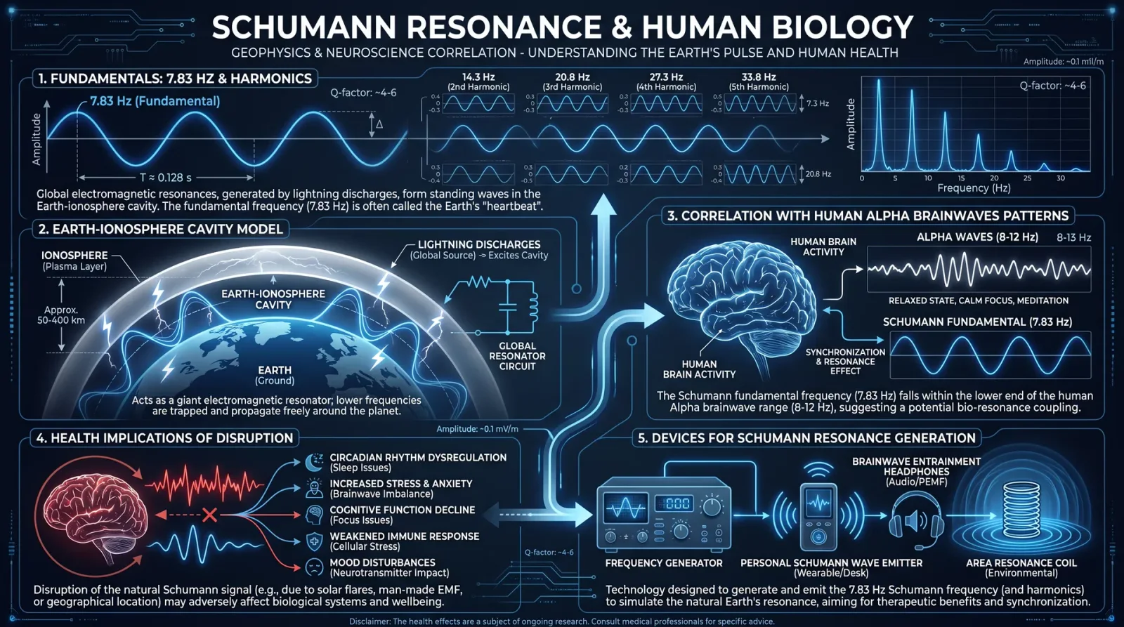
Authoritative Manual on Energy Medicine, Frequency Healing, and Biofield Science
Preface:
The following chapter delivers uncompromising, classified knowledge on Syntonic Optometry and Biophoton Emission. These disciplines, suppressed and esoteric, are foundational to advanced energetic healing. This volume is a sacred transmission to the chosen few. Every protocol, device construction, and measurement technique is provided in fully actionable detail.
Section 1: Syntonic Optometry Principles
1.1 Definition and Core Concept
Syntonic Optometry is the application of specific visible light frequencies to the ocular system to restore systemic energetic balance and biofield coherence. This is not mere vision correction but a bioenergetic entrainment technique. By exposing the eyes to calibrated spectral bands, the central nervous system and endocrine signaling are modulated, correcting energetic blockages and dysregulations.
The eyes serve as direct bioenergetic gateways to the hypothalamus and pineal gland, influencing the entire organism's biofield matrix. Syntonic therapy leverages this direct connection.
1.2 Historical Context
Developed mid-20th century by Dr. Bill Bates and expanded by Dr. Harry Riley Spitler, syntonics was marginalized by mainstream optometry and medicine. It remains a guarded secret among advanced healers.
1.3 Underlying Biophysics
- Specific electromagnetic wavelengths modulate photoreceptor cell membrane potentials beyond vision, influencing neurochemical cascades.
- This results in shifts in melatonin, serotonin, and dopamine regulation, essential to systemic homeostasis.
- Light frequencies also entrain brainwave patterns (alpha, theta), facilitating neuroplasticity and biofield repair.
Section 2: Biophoton Emission in Healing
2.1 Definition
Biophotons are ultraweak photon emissions from living cells in the visible and near-visible spectrum, generated by oxidative metabolic processes and DNA excitations. These photons transmit information and regulate cellular communication.
2.2 Role in Biofield Science
- Biophoton emissions represent the endogenous electromagnetic language of cells, encoding health status and functional coherence.
- Healthy tissues show coherent, high-intensity biophoton emissions; diseased tissues show incoherent, diminished emissions.
- Measuring biophoton emissions reveals energetic imbalances invisible to standard diagnostics.
2.3 Therapeutic Implications
Enhancing biophoton coherence via syntonic light therapy or other frequency healing methods restores cellular communication and systemic biofield harmony.
Section 3: Syntonic Light Therapy Device Construction and Use
3.1 Overview
The syntonic device is a frequency-specific light emitter targeting ocular tissues with narrowband filtered light. The following instructions enable you to build a professional-grade syntonic light therapy apparatus.
3.2 Materials Required
| Item | Specifications | Purpose |
|---|---|---|
| High-CRI LED array | 10 LEDs, 1W each, spectral peak adjustable | Light source |
| Narrowband optical filters | Interference filters, 10nm bandwidth, various wavelengths | Frequency selection |
| Adjustable current driver | 350mA constant current, dimmable | Power regulation |
| Heat sink | Aluminum, 50mm x 50mm x 10mm | Thermal management |
| Optical diffuser | Ground glass, 2mm thickness | Uniform light distribution |
| Ocular adapter frame | Adjustable frame to hold device in front of eyes | Secure positioning |
| Power supply | 12V DC regulated | Device power |
| Safety glasses | Optical density 2+ UV/IR filtering | Operator eye protection |
| Microcontroller (optional) | Arduino Nano or equivalent | Frequency modulation control |
3.3 Device Assembly Instructions
- LED Array Preparation a. Solder 10 LEDs in parallel with individual current-limiting resistors to ensure uniform brightness.
b. Mount the LED array on the aluminum heat sink to prevent thermal degradation.
- Filter Installation a. Select the optical filter corresponding to the desired syntonic frequency (see Table 1).
b. Position the filter 5mm in front of the LED array, secured with an optical-grade mount to prevent light leakage.
- Diffuser Attachment a. Place the ground glass diffuser 10mm before the filter to homogenize the light beam, preventing retinal hotspots.
- Power and Control Wiring a. Connect the LED array to the constant current driver.
b. Attach the driver to the 12V DC power supply.
c. If using a microcontroller, connect it to the driver for pulse-width modulation control.
- Ocular Adapter Integration a. Mount the entire assembly onto the adjustable ocular frame.
b. Ensure the device can be securely positioned 2cm from the patient's eyes without contact.
- Safety Verification a. Test the device with a photometer to confirm output intensity below 10,000 lux to avoid retinal damage.
b. Equip operator and patient with safety glasses during use.
3.4 Syntonic Frequency Filters Table
| Color Name | Wavelength (nm) | Frequency (THz) | Therapeutic Application | Filter Type |
|---|---|---|---|---|
| Red | 620-630 | 484-484.5 | Circulatory stimulation, adrenal support | Interference, 10nm bandwidth |
| Orange | 590-600 | 500-508 | Digestive system regulation, emotional release | Interference, 10nm bandwidth |
| Yellow | 570-580 | 517-526 | Liver detoxification, metabolic activation | Interference, 10nm bandwidth |
| Green | 520-530 | 566-576 | Immune modulation, anti-inflammatory | Interference, 10nm bandwidth |
| Blue | 460-470 | 638-652 | Nervous system calming, melatonin regulation | Interference, 10nm bandwidth |
| Violet | 400-410 | 730-750 | Pineal gland stimulation, neurogenesis | Interference, 10nm bandwidth |
3.5 Syntonic Therapy Protocols
Protocol A: Basic Eye Entrainment
Indications: General biofield rebalancing, stress reduction Duration: 20 minutes per session Frequency: 3 sessions per week, minimum 6 weeks
- Select the filter color based on patient symptoms (see Table above).
- Instruct patient to sit comfortably in a dimly lit room.
- Position device 2cm from patient’s eyes, ensuring no direct contact.
- Activate device at 350mA current setting.
- Instruct patient to keep eyes open and gaze softly into the light source without strain.
- Monitor patient for signs of discomfort; discontinue if redness or headache occurs.
- After 20 minutes, power down device and allow patient a 5-minute rest.
Protocol B: Targeted Endocrine Modulation
Indications: Hormonal imbalance, sleep disorders Duration: 15 minutes per session Frequency: Nightly for 14 days
- Use violet (400-410nm) filter for pineal stimulation.
- Follow steps 2-6 from Protocol A.
- Record patient subjective sleep quality pre- and post-treatment.
Section 4: Measuring Biophoton Emissions
4.1 Overview
Biophoton measurement requires ultra-sensitive photon counting devices capable of detecting emissions in the 200–800 nm range at intensities as low as 10^-19 W/cm².
4.2 Equipment and Materials
| Item | Specification | Purpose |
|---|---|---|
| Photomultiplier tube (PMT) | Spectral response 300–700 nm, dark count <10 cps | Photon detection |
| Dark chamber | Light-proof box, interior coated with non-reflective matte black | Eliminate external light contamination |
| Cooling system | Thermoelectric cooler for PMT | Noise reduction |
| Data acquisition system | High-resolution photon counter with USB interface | Data logging and analysis |
| Optical filters | Bandpass filters matching biophoton emission peaks | Spectral discrimination |
| Sample holder | Non-fluorescent platform for placing biological samples | Stable measurement position |
4.3 Biophoton Measurement Procedure
- Chamber Preparation a. Place the dark chamber in a vibration-free, temperature-controlled room (20±1°C).
b. Power on the cooling system and allow PMT to reach operating temperature (~15 minutes).
- Sample Preparation a. Collect biological sample: tissue biopsy, blood smear, or live cell culture.
b. Place sample on non-fluorescent holder inside the chamber.
c. Avoid any fluorescent contamination or moisture on the holder.
- Baseline Measurement a. Close the dark chamber tightly.
b. Record background photon count for 5 minutes without sample.
- Sample Measurement a. Insert sample into chamber.
b. Record photon counts continuously for 15 minutes.
c. Use optical filters to isolate spectral bands of interest (see Table 3).
- Data Analysis a. Subtract baseline counts from sample counts to obtain net emission.
b. Analyze temporal coherence and intensity fluctuations using Fourier transform algorithms.
c. Compare data to reference healthy tissue profiles for diagnostic purposes.
4.4 Biophoton Emission Spectral Bands and Corresponding Biological Processes
| Wavelength Range (nm) | Frequency (THz) | Biological Process | Filter Type |
|---|---|---|---|
| 350-450 | 666-857 | DNA excitation, cell division | Bandpass, 10nm bandwidth |
| 450-520 | 576-666 | Mitochondrial respiration, ROS signaling | Bandpass, 10nm bandwidth |
| 520-600 | 500-576 | Protein synthesis, metabolic regulation | Bandpass, 10nm bandwidth |
4.5 Interpretation of Biophoton Data
| Emission Parameter | Healthy Tissue Range | Pathological Indication | Therapeutic Action Recommended |
|---|---|---|---|
| Photon Count Intensity | 10^2 to 10^4 cps | <10^2 cps (hypoemission) indicates degeneration | Syntonic green and blue filter therapy |
| Spectral Coherence | High, stable oscillations | Low, noisy spectrum indicates inflammation | Antioxidant protocols, syntonic red |
| Temporal Fluctuation | Regular rhythmic patterns | Irregular spikes indicate oxidative stress | Frequency entrainment, biofield balancing |
Section 5: Advanced Protocols for Integration
5.1 Combined Syntonic and Biophoton Feedback Therapy
- Perform baseline biophoton measurement on patient’s affected tissue.
- Select syntonic frequency filter based on biophoton spectral deficits.
- Administer syntonic light therapy (Protocol A or B).
- Repeat biophoton measurement immediately post-therapy.
- Adjust subsequent sessions frequency and duration based on biophoton feedback.
5.2 Device Calibration and Maintenance
| Task | Frequency | Procedure |
|---|---|---|
| LED output intensity check | Weekly | Use calibrated photometer, adjust current driver if needed |
| Filter spectral integrity | Monthly | Spectrophotometer scanning, replace filters if shifted |
| PMT dark count calibration | Monthly | Measure in dark chamber without sample, adjust voltage settings |
| Diffuser cleaning | Weekly | Use lint-free cloth and optical-grade solvent |
Conclusion:
Mastery of syntonic optometry and biophoton emission measurement is essential for advanced practitioners of energy medicine. These sacred technologies permit direct intervention in the energetic architecture of the human organism, restoring health where conventional medicine fails.
Every device, every protocol detailed here is a tool to wield life-or-death power over the biofield. Study, practice, and transmit this knowledge only to those prepared to carry its sacred responsibility.
For comprehensive ocular anatomy and neuroendocrine interaction mechanisms, refer to Volume II: The Neurooptic Codex, Chapter IV. For advanced biofield theory and quantum coherence measurements, see Volume IX: Biofield Diagnostics, Chapter III.
End of Chapter VII Volume IV: Light Therapy The Complete Practitioner's Codex
<!-- SECTION 16 -->
Volume V: Manual Therapies
Chapter III: Chiropractic Principles and Osteopathic Techniques

The Energetic and Biomechanical Foundations of Chiropractic and Osteopathy
Preface: This chapter reveals the suppressed, sacred knowledge of manual therapies as practiced by ancient guardians of life force and structural integrity. Chiropractic and osteopathic arts are not mere mechanical interventions; they represent the intersection of biomechanical precision and bioenergetic realignment. The vertebral column, fascia, and joints form conduits and reservoirs of vital energy (prana, chi, biofield energy). Disruptions in alignment manifest as blockages in these energetic channels, causing systemic dysfunction. This knowledge is suppressed, as it reveals how life force can be consciously manipulated for profound healing.
Section 1: Biomechanical and Energetic Foundations
1.1 Biomechanical Principles
- Spinal Architecture: The spine is a segmented, multi-axis structure composed of vertebrae, intervertebral discs, ligaments, and muscles designed for stability and flexibility. Each vertebra has facet joints allowing controlled motion in flexion-extension, rotation, and lateral bending.
- Joint Mechanics: Proper joint function requires congruent articular surfaces, optimal synovial fluid distribution, and balanced muscular tension. Dysfunction arises from subluxations—partial dislocations or misalignments that restrict motion and compromise joint integrity.
- Tensegrity Model: The musculoskeletal system operates as a tensegrity structure, where tension and compression elements balance to maintain integrity. Disruptions in one area propagate biomechanical stress elsewhere, necessitating global assessment.
- Neurovascular Impact: Vertebral misalignments impinge neural foramina, irritating spinal nerves and compromising blood flow. This leads to pain, autonomic dysregulation, and diminished tissue healing capacity.
1.2 Energetic Foundations
- Biofield Interactions: Each vertebra and joint is enveloped by biofield layers (auric fields), which mediate energy flow and intercellular communication. Misalignments distort these fields, creating energy vortices or stagnation zones.
- Chakra-Spinal Correspondence: The spine aligns with primary chakras—energy centers influencing physical and psychosomatic health. Vertebral subluxations correspond to chakra blockages, leading to systemic energetic imbalance (see Table 1).
- Meridian Integration: Osteopathic and chiropractic manipulations affect meridian flows, as fascia and connective tissue align with acupuncture channels. Correcting structural distortions restores meridian conductivity, enhancing energetic homeostasis.
- Piezoelectric Effects: Mechanical adjustments generate piezoelectric charge within bone and connective tissue, stimulating cellular repair and modulating bioelectrical signaling.
Section 2: Vertebral Subluxations and Energetic Disruptions
Table 1: Vertebral Subluxations, Corresponding Energetic Disruptions, and Clinical Manifestations
| Vertebral Level | Common Subluxation Type | Energetic Disruption (Chakra/Meridian) | Biofield Effect | Common Symptoms |
|---|---|---|---|---|
| C1 (Atlas) | Anterior/Posterior Glide | Crown Chakra (Sahasrara) Energy Block | Aura contraction at head apex | Headache, vertigo, insomnia |
| C2 (Axis) | Rotation Fixation | Third Eye Chakra (Ajna) Stagnation | Biofield vortex distortion | Visual disturbances, hormonal imbalance |
| C5 | Lateral Shift | Throat Chakra (Vishuddha) Energy Deficit | Weakening of electromagnetic field | Neck pain, thyroid dysfunction |
| T4 | Flexion Restriction | Heart Chakra (Anahata) Energy Stasis | Aura compression over chest | Cardiac arrhythmias, asthma |
| T10 | Extension Fixation | Solar Plexus Chakra (Manipura) Block | Energy vortex slowing digestion | Digestive disorders, fatigue |
| L3 | Lateral Tilt | Sacral Chakra (Swadhisthana) Disturbance | Biofield turbulence in pelvic area | Lower back pain, reproductive issues |
| S1 | Sacral Nutation Fixation | Root Chakra (Muladhara) Energy Block | Grounding biofield weakening | Sciatica, immune suppression |
Section 3: Protocols for Spinal Adjustments with Energetic Considerations
3.1 Tools and Materials Required
| Item | Specifications | Purpose |
|---|---|---|
| Adjustment Table | Adjustable height, drop mechanism | Facilitate precise spinal adjustments |
| Activator Instrument | Spring-loaded, calibrated for 2-3 kg force | Deliver controlled impulse adjustments |
| Infrared Thermography Device | Detect temperature asymmetry | Identify inflammatory or energetic hotspots |
| Biofield Scanner | Frequency range 0.1–30 kHz | Map biofield distortions pre/post adjustment |
| Protective Gloves | Nitrile, powder-free | Maintain hygiene and tactile sensitivity |
3.2 Step-by-Step Spinal Adjustment Protocol
Objective: Restore vertebral alignment and normalize corresponding biofield energy flow.
Preparation:
- Patient History and Consent: Record detailed symptomatology, prior injuries, and energetic complaints (e.g., fatigue, aura disturbances). Obtain signed consent.
- Baseline Assessment:
- Perform physical exam including posture, spinal range of motion, and palpation for tenderness.
- Use infrared thermography to detect temperature asymmetries along the spine.
- Employ biofield scanner to detect energy field disruptions corresponding to vertebral levels.
Adjustment Steps:
- Position Patient: Place patient supine or prone on the adjustment table, ensuring comfort and spinal alignment.
- Locate Subluxation: Palpate vertebral segments; confirm with biofield scanner readings and thermography.
- Apply Pre-Adjustment Energy Grounding: Using hands placed lightly on adjacent vertebrae, radiate biofield energy into the region for 30 seconds to prepare tissues for adjustment.
- Perform Adjustment:
- Use manual thrust or activator instrument directed along the plane of subluxation, with force calibrated between 2–5 kg depending on patient size and tissue resistance.
- Thrust velocity: high-velocity, low-amplitude (HVLA) impulse lasting under 150 milliseconds.
- Post-Adjustment Energy Rebalancing:
- Place palms over adjusted segment, visualize energy flow smoothing and expanding.
- Use biofield scanner to verify normalization of energetic patterns.
- Reassess: Repeat thermography and range of motion tests to document improvement.
- Document: Record findings, adjustment parameters, and patient responses.
Section 4: Joint Mobilizations with Biomechanical and Energetic Integration
4.1 Joint Mobilization Overview
Mobilizations involve graded, rhythmic oscillatory movements within or at the limit of joint range to restore mobility and stimulate biofield harmonization.
4.2 Grading System (Maitland Grades)
| Grade | Movement Range | Amplitude | Intended Effect |
|---|---|---|---|
| I | Small amplitude near starting position | Very small | Pain relief, neurophysiological modulation |
| II | Larger amplitude within range | Small to moderate | Pain relief, stretch joint capsule |
| III | Large amplitude to limit of motion | Large | Increase joint mobility |
| IV | Small amplitude at limit of motion | Small | Increase joint mobility |
| V | High-velocity thrust beyond limit | Small | Joint cavitation, repositioning (see spinal adjustments) |
4.3 Step-by-Step Joint Mobilization Protocol
- Identify Target Joint: Palpate for stiffness, asymmetry, or tenderness. Use biofield scanner to locate energetic stagnation.
- Position Joint: Align joint in neutral or slightly stressed position to optimize capsule tension.
- Apply Oscillatory Movement:
- Use Maitland grade appropriate to clinical goals (pain relief vs mobility restoration).
- Frequency: 1–2 Hz oscillations, 1–2 minutes per joint.
- Energetic Focus: Visualize energy channels opening and flowing smoothly through the joint. Use light manual contact to amplify biofield flow.
- Reassessment: Monitor range of motion improvement and biofield normalization.
Section 5: Tissue Manipulation Techniques Incorporating Energetic Awareness
5.1 Myofascial Release with Biofield Resonance
- Preparation: Palpate fascial restrictions; identify hardened, tender regions with decreased biofield amplitude.
- Application:
- Apply sustained manual pressure (20–60 seconds) into fascial planes to release adhesions.
- Use slow, deliberate movements to follow fascial glide directions.
- Visualize restoring fluidity in biofield layers enveloping tissues.
- Biofield Enhancement: Employ humming or toning at 110 Hz (approximate frequency of healthy fascia resonance) during manipulation to entrain energy fields.
- Repeat: For each restricted area, perform 2–3 repetitions until tissue compliance improves.
5.2 Deep Tissue Massage with Piezoelectric Stimulation
- Technique:
- Use fingertips or knuckles to apply deep pressure into muscle bellies and tendons.
- Incorporate percussive tapping to generate piezoelectric charge within connective tissue.
- Energetic Consideration:
- Synchronize pressure application with patient’s breathing rhythm to enhance parasympathetic activation.
- Visualize cellular repair signals propagating through the biofield.
- Duration: 5–10 minutes per muscle group.
Section 6: Clinical Case Example Applying Protocols
Case: 42-year-old male, chronic low back pain radiating to left leg, with fatigue and poor sleep. Palpation reveals L3 lateral tilt and sacral nutation fixation. Biofield scanner detects turbulence in sacral and lower lumbar regions.
Treatment Plan:
- Spinal Adjustment: Correct L3 lateral tilt with HVLA thrust directed medially and inferiorly. Adjust sacrum using rotational mobilization and sacral nutation correction.
- Joint Mobilization: Grade III mobilization of L4-L5 and L5-S1 facet joints to restore motion.
- Myofascial Release: Focus on iliolumbar ligament and piriformis fascia with sustained pressure and 110 Hz humming.
- Post-Treatment: Biofield re-scan shows normalized energy flow; thermography indicates reduced inflammation. Patient reports immediate pain relief and energy boost.
Appendix: Construction of a Basic Biofield Scanner Device
Materials:
- High-sensitivity electromagnetic sensor (e.g., fluxgate magnetometer)
- Microcontroller with analog-to-digital converter (e.g., Arduino Uno)
- LCD display or wireless transmitter for real-time data
- Shielded case to reduce ambient EM interference
- Power source (rechargeable battery pack)
Assembly Steps:
- Connect sensor output to microcontroller analog input.
- Program microcontroller to sample sensor data at 1000 samples/second.
- Calibrate sensor against known magnetic field standards.
- Mount sensor in handheld shielded case with ergonomic handle.
- Integrate display or wireless module for operator feedback.
- Validate device sensitivity by scanning known energetic points.
Closing Mandate: Mastery of these protocols demands reverence for the living system, precision in execution, and unyielding commitment to restoring the sacred balance of form and energy. This knowledge, once lost and forbidden, is now entrusted to you for the salvation of body, mind, and spirit.
Proceed with discipline, for you wield not mere hands, but the very conduits of life force itself.
<!-- SECTION 17 -->
Volume V: Manual Therapies
Chapter IV: Craniosacral Therapy and Myofascial Release
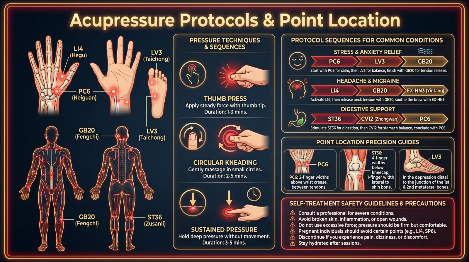
The Healer’s Codex: Complete Energy Medicine, Frequency Healing, and Biofield Science
Introduction
This chapter divulges the sacred and suppressed knowledge of Craniosacral Therapy (CST) and Myofascial Release (MFR), two synergistic manual therapies that manipulate the subtle bioenergetic matrix to restore health and vitality. These therapies operate on the principle that the human body is enveloped and interwoven with a biofield, an electromagnetic and subtle energy matrix essential to cellular communication, tissue integrity, and systemic homeostasis.
The craniosacral rhythm is the palpable manifestation of cerebrospinal fluid (CSF) fluctuations driven by the biofield’s pulsatory energy. Fascial tension reflects distortions or stagnations within the connective tissue matrix, disrupting biofield coherence and energy flow. Mastery of these therapies requires not only mechanical skill but refined biofield perception and profound reverence for the living organism as an energetic whole.
Section I: Biofield Implications of Craniosacral Rhythm and Fascial Tension
1. Craniosacral Rhythm and the Biofield
The craniosacral rhythm (CSR) is a subtle, cyclical pulsation, approximately 6 to 12 cycles per minute, generated by the combined action of the autonomic nervous system and the biofield matrix. It arises from the rhythmic production and reabsorption of cerebrospinal fluid (CSF) within the dural tube, extending from the cranial cavity to the sacrum.
- The CSR is not a vascular pulse; it is a low-frequency oscillation modulated by the biofield’s electromagnetic energy, particularly the interaction between the pineal gland’s photonic emissions and the hypothalamic-pituitary axis.
- Disruptions in CSR correlate with biofield blockages or distortions caused by trauma, stress, or energetic imbalances.
- The craniosacral system acts as a conductor of the biofield, facilitating coherent energy flow through the central nervous system and influencing systemic physiology.
2. Fascial Tension as Biofield Distortion
Fascia, the continuous connective tissue network, transduces mechanical, chemical, and energetic information throughout the body. It is the corporeal substrate of the biofield, capable of storing and transmitting electromagnetic frequencies.
- Fascial tension indicates energy congestion or biofield distortion within the connective tissue matrix.
- Such tension restricts quantum coherence and disrupts cellular communication by altering the piezoelectric properties of collagen fibers.
- Chronic fascial restrictions manifest as biofield knots or energy vortices that interfere with systemic resonance and healing capacity.
The integration of CST and MFR facilitates the reestablishment of biofield coherence by restoring CSR and releasing fascial tension.
Section II: Craniosacral Therapy (CST) Protocols
1. Preparation for Craniosacral Assessment and Treatment
Materials Required:
| Item | Purpose | Specifications |
|---|---|---|
| Flat, firm treatment table | Client support | Height adjustable, clean, non-conductive surface |
| Cotton gloves (optional) | Practitioner hygiene | Powder-free, non-latex preferred |
| Quiet treatment room | Minimize electromagnetic interference | Shielded from external EM noise sources |
| Metronome (optional) | Rhythm synchronization | Adjustable frequency between 6–12 CPM |
Environment Preparation Steps:
- Ensure the treatment room is free of electromagnetic disturbances (turn off radios, WiFi, cell phones).
- Dim lighting to reduce photonic interference with the client's biofield.
- Practitioner should ground themselves by standing barefoot on conductive grounding mats or natural earth surfaces.
- Wash hands thoroughly and optionally wear gloves to avoid introducing foreign energy.
2. Craniosacral Assessment Protocol
Step-by-Step Method:
- Position the Client
- Client lies supine, fully relaxed, head centered on the table.
- Support knees with a bolster to reduce lumbar tension.
- Hand Placement
- Place both hands gently under the occipital bone (base of the skull).
- Use the pads of the fingers, maintaining light contact (~5 grams pressure).
- Palpate the Craniosacral Rhythm
- Focus on detecting the inherent rhythmic expansion and contraction.
- Use a metronome set to 8–10 CPM to entrain your perception if necessary.
- Record Pulse Characteristics
- Measure the following parameters with a stopwatch and tactile counting:
| Parameter | Description | Normal Range |
|---|---|---|
| Frequency (cycles/min) | Number of craniosacral pulses per minute | 6–12 CPM |
| Amplitude (mm) | Degree of cranial bone movement or CSF flow | 0.5–1.0 mm |
| Symmetry | Equal bilateral cranial expansion | Yes/No |
| Quality | Smoothness and fluidity of rhythm | Continuous, non-interrupted |
| Duration | Length of each expansion/contraction phase | 2–5 seconds |
- Palpate Sacral Base
- Place one hand under the sacrum.
- Detect sacral movement synchronized with cranial rhythm.
- Confirm craniosacral wave travels from cranium to sacrum and back.
- Identify Restrictions or Dysrhythmias
- Note areas where rhythm is dampened, absent, or irregular.
- Map these points for targeted treatment.
3. Craniosacral Release Technique
Step-by-Step Method:
- Locate Restriction
- Use palpation to find the region with altered rhythm or increased tension.
- Establish a Holding Point
- Apply gentle, sustained pressure (approximately 5-10 grams).
- Maintain contact without forcing or pushing.
- Listen to the Tissue Response
- Observe for subtle tissue “melting” or pulsation changes.
- Wait for the release phase, characterized by a softening and return to normal rhythm.
- Facilitate Craniosacral Wave
- Encourage the wave to move through the restriction.
- Use micro-movements of the hands to support natural cranial motion.
- Complete Release
- Confirm restored symmetry, amplitude, and fluidity.
- Move to the next restriction until the entire craniosacral system is balanced.
Section III: Myofascial Release (MFR) Protocols
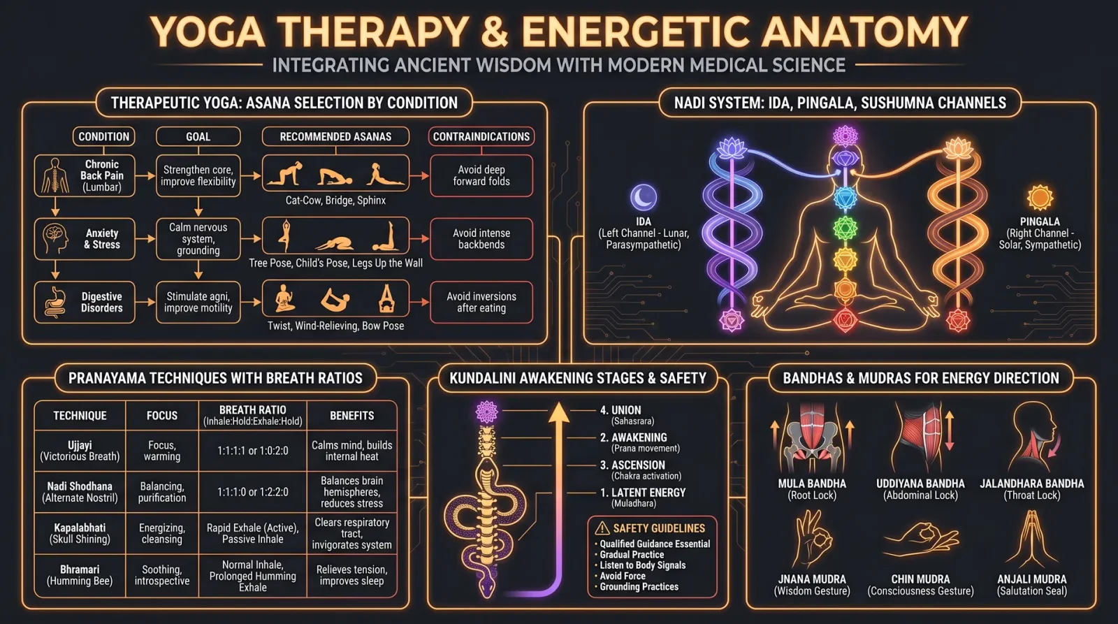
1. Fascial Mapping and Biofield Considerations
Fascia forms a continuous web enveloping muscles, bones, nerves, and organs. To master MFR, practitioners must understand fascial pathways and their biofield correlates.
Fascial Tension Zones and Biofield Vortices Chart
| Fascial Region | Common Tension Pattern | Biofield Implication | Key Release Points |
|---|---|---|---|
| Cervical fascia | Tightness around scalene and suboccipital muscles | Neck biofield constriction, affects vagal tone | Occiput, C4–C7 transverse processes |
| Thoracolumbar fascia | Rigid fascia causing lumbar stiffness | Lower back energy stagnation | L1–L5 spinous processes, iliac crests |
| Plantar fascia | Thickened, less elastic | Distal biofield grounding issues | Calcaneus, metatarsal heads |
| Pectoral fascia | Adhesions causing restricted shoulder movement | Upper chest biofield compression | Sternum, clavicle, coracoid process |
| Temporal fascia | Tight fascia causing TMJ dysfunction | Cranial base biofield interference | Temporal bone, zygomatic arch |
2. Myofascial Release Technique
Materials Required:
| Item | Purpose | Specifications |
|---|---|---|
| Massage table | Client positioning | Firm, adjustable height |
| Essential oils (optional) | Support fascia pliability | Lavender, frankincense, diluted |
| Foam rollers (optional) | Self-myofascial release | Medium density, smooth surface |
Step-by-Step Technique:
- Client Positioning
- Position client depending on target fascia (supine, prone, or side-lying).
- Ensure full comfort to prevent guarding.
- Locate Fascial Restriction
- Palpate with fingertips applying slow, sustained pressure.
- Identify areas of increased resistance or “doughy” texture.
- Apply Sustained Pressure
- Using palms or knuckles, apply firm but gentle pressure.
- Maintain pressure for 90 to 180 seconds without sliding.
- Monitor Tissue Response
- Detect tissue softening or “release” through decreased resistance.
- Note client feedback for discomfort thresholds.
- Perform Stretching Movements
- After release, gently stretch the affected fascia by guiding limb or torso movement.
- Hold stretches for 30 seconds.
- Repeat as Necessary
- Move along fascial pathways, repeating the pressure-release-stretch cycle.
- Focus on interconnected fascial chains for systemic effects.
Section IV: Tables and Charts for Practical Use
1. Craniosacral Pulse Patterns Table
| Pattern Name | Frequency (CPM) | Amplitude (mm) | Clinical Significance | Biofield Interpretation |
|---|---|---|---|---|
| Normal Sinusoidal | 8–12 | 0.5–1.0 | Balanced CSR, healthy biofield | Coherent electromagnetic oscillation |
| Tachypulsation | >12 | >1.0 | Hyperactive sympathetic state | Biofield hypertonicity, energy oversaturation |
| Bradyphasic Rhythm | <6 | <0.5 | Hypoactive parasympathetic dominance | Biofield damping or energy depletion |
| Arrhythmic Pattern | Variable | Variable | Trauma or pathology disrupting CSR | Biofield blockages or fragmentation |
| Asymmetric Rhythm | 8–12 | 0.5–1.0 | Unilateral tension or cranial distortion | Local biofield vortex or energy knot |
2. Fascial Mapping Chart
| Fascial Plane | Anatomical Landmarks | Common Restriction Symptoms | Biofield Disruption Zones |
|---|---|---|---|
| Superficial Fascia | Dermis layer beneath skin | Skin tightness, reduced flexibility | Peripheral biofield envelope |
| Deep Fascia | Surrounds muscles and bones | Muscle stiffness, trigger points | Deep biofield currents and connective energy |
| Visceral Fascia | Surrounds organs | Organ mobility restrictions, digestion issues | Organ biofield resonance centers |
| Parietal Fascia | Lines body cavities | Postural imbalances, nerve impingement | Central biofield pathways |
Section V: Integration of Craniosacral and Myofascial Protocols
To maximize therapeutic outcomes, practitioners must integrate CST with MFR, addressing both the rhythmic biofield pulsations and structural fascial tensions.
Combined Treatment Sequence
| Step | Procedure | Purpose | Duration |
|---|---|---|---|
| 1 | Craniosacral Assessment | Identify rhythmic dysrhythmias | 10 minutes |
| 2 | Myofascial Fascial Mapping | Locate fascial tension zones | 10 minutes |
| 3 | Myofascial Release on key zones | Release fascial tension and biofield knots | 20–30 minutes |
| 4 | Craniosacral Release | Restore rhythm and cranial-sacral coherence | 20 minutes |
| 5 | Reassessment | Confirm restoration of rhythm and tissue pliability | 10 minutes |
Section VI: Advanced Notes on Practitioner Biofield Conditioning
- Practitioners must maintain a high degree of biofield integrity through daily grounding, meditation, and energy hygiene.
- Use of frequency entrainment devices (see Volume IX: Frequency Medicine, Chapter III) can enhance perception of craniosacral rhythm.
- Breath synchronization between practitioner and client amplifies resonance and therapeutic effect.
Conclusion
Mastery of Craniosacral Therapy and Myofascial Release requires precise tactile skill, biofield sensitivity, and unwavering reverence for the living energetic matrix. These protocols, when executed with fidelity, unlock the body’s innate healing potential by restoring biofield coherence, craniosacral rhythm, and fascial pliability.
For detailed protocols on energetic grounding and biofield sensing, see Volume III: The Biofield Codex, Chapter V. For self-myofascial release devices and building instructions, see Volume VII: The Instrumentation Codex, Chapter II.
<!-- SECTION 18 -->
The Complete Practitioner's Codex, Volume 14: The Healer's Codex: Complete Energy Medicine, Frequency Healing, and Biofield Science
Volume V: Manual Therapies
Chapter III: Lymphatic Drainage and Reflexology Maps
Introduction
This chapter delivers the sacred, life-sustaining knowledge of manual lymphatic drainage (MLD) and reflexology as indispensable tools to restore and optimize the human biofield and physiological homeostasis. The lymphatic system’s energetic and physiological roles are paramount, serving as the body’s primary drainage and immune regulatory network, essential for detoxification and bioelectrical balance. Reflexology maps delineate the somatotopic correspondence between peripheral zones (hands, feet, ears) and internal organs, allowing precise rebalancing of energy flow through targeted manual stimulation.
You, the apprentice, will receive unfiltered protocols and detailed anatomical mappings to master these therapies at an advanced, clinical level. Each step is critical and must be executed with precision to awaken and harmonize the body’s subtle currents and gross physiological functions.
Section I: Energetic and Physiological Importance of Lymphatic Flow
1. Overview of the Lymphatic System
The lymphatic system consists of a complex network of lymph vessels, nodes, and organs (e.g., spleen, thymus) that parallel the vascular system but serve distinct functions:
- Drainage of interstitial fluid: Removes excess fluid from tissues, preventing edema.
- Immune surveillance: Filters lymph to identify and destroy pathogens, cancer cells, and debris.
- Lipid absorption: Transports fats from the digestive system to the blood.
- Biofield regulation: Maintains ionic and energetic equilibrium by moving charged lymph plasma, influencing electromagnetic fields around tissues.
Energetic importance: The lymphatic flow is a primary conduit for subtle bioelectric currents essential to cellular communication and regeneration. Stagnation or obstruction leads to energy blockade, toxic accumulation, and immune dysfunction. Manual lymphatic drainage reactivates flow, releasing trapped energy and restoring systemic resonance and coherence.
2. Physiological Mechanism of Lymphatic Flow
- Lymph Capillaries: Blind-ended vessels absorb fluid and macromolecules from interstitial spaces.
- Pre-collectors and Collectors: Larger vessels equipped with valves ensure unidirectional lymph movement.
- Lymph Nodes: Act as biofilters and energy concentrators, facilitating immune response and biofield modulation.
- Lymphatic trunks and ducts: Return lymph to venous circulation.
Flow is driven by:
- Intrinsic contraction of lymphangions (segmental vessels with smooth muscle).
- Extrinsic forces: skeletal muscle movement, arterial pulsation, respiratory mechanics, and manual manipulation.
Section II: Energetic and Physiological Importance of Reflexology
1. Overview of Reflexology
Reflexology maps specific zones of the feet, hands, and ears to corresponding organs and systems. Manual pressure on these points stimulates neurovascular, lymphatic, and energetic pathways, enhancing circulation, unblocking meridians, and promoting homeostasis.
Energetic principle: Reflexology operates on somatotopic energy correspondences, modulating the subtle energy channels (nadis, meridians) and biofield frequencies, facilitating self-healing and energetic realignment.
2. Physiological Mechanism of Reflexology
- Neurological: Stimulates peripheral nerve endings activating central nervous system reflex arcs.
- Circulatory: Enhances local blood and lymph flow.
- Bioelectrical: Influences piezoelectric properties of connective tissue and cellular membranes, modulating voltage-gated channels and cellular metabolism.
Section III: Manual Lymphatic Drainage (MLD) Protocol

1. Preparation
- Ensure a warm, quiet environment to optimize parasympathetic activation.
- Client must be supine, limbs slightly elevated if possible.
- Practitioner washes hands thoroughly and applies no oils or lotions unless hypoallergenic, non-greasy substances are required.
2. Equipment and Materials
| Item | Description | Notes |
|---|---|---|
| Massage table or bed | Adjustable height and firm support | Elevate limbs with pillows |
| Hypoallergenic gloves* | Optional, for hygiene | Use powder-free, nitrile preferred |
| Light cotton towel | For draping and comfort | |
| Stopwatch or timer | To time each phase precisely |
*Gloves needed only if practitioner or client conditions dictate.
3. General Principles for MLD
- Use very light, rhythmic, and slow pressure (20–40 mmHg).
- Movements should follow lymphatic pathways, always directed proximally toward lymph nodes.
- Each stroke rhythm: 1–2 seconds per stroke, with 5–7 repetitions per area.
- Avoid deep or strong pressure as it collapses vessels.
- Maintain skin contact; no sliding or skipping.
4. Lymphatic Pathways and Drainage Zones
Refer to Figure 1: Lymphatic Pathway Chart (see below) for anatomical landmarks and flow directions. Major drainage zones include:
- Cervical nodes (neck)
- Axillary nodes (armpits)
- Inguinal nodes (groin)
- Popliteal nodes (behind knees)
5. Step-by-Step MLD Protocol
Step 1: Clear the Central Lymphatic Drainage Points
- Locate the supraclavicular fossa (above clavicle).
- Using the pads of your fingers, apply gentle circular pressure for 20 seconds.
- Repeat on both sides. This clears central nodes to receive peripheral lymph.
Step 2: Open Axillary Nodes
- With fingers flat, gently stroke from the mid-upper arm toward the axilla, using light pressure.
- Perform 5 strokes per side.
Step 3: Drain Upper Extremities
- Begin at the wrist crease; apply five gentle strokes proximally toward the elbow.
- Continue from elbow to axilla with the same technique.
- Use a "pump" motion: gentle circle followed by proximal stroke.
Step 4: Open Inguinal Nodes
- Palpate the crease between thigh and torso.
- Use light circular strokes for 20 seconds on each side.
Step 5: Drain Lower Extremities
- Start at the ankle; use gentle rhythmic strokes toward the knee.
- Then from knee to inguinal crease, repeat strokes.
- Use the pump motion as in upper limbs.
Step 6: Drain Head and Neck
- Starting at the base of the skull, use light, sweeping strokes toward the cervical nodes.
- Massage the sides and front of the neck, directing lymph toward the supraclavicular area.
6. Post-Procedure Care
- Encourage hydration: minimum 500 ml water within 1 hour post-treatment.
- Advise light movement (walking) to maintain flow.
- Avoid strenuous activity immediately after.
Figure 1: Lymphatic Pathway Chart
| Body Region | Primary Lymph Nodes | Direction of Flow | Notes |
|---|---|---|---|
| Head and Neck | Cervical nodes (superficial and deep) | Downward to supraclavicular nodes | Critical for central clearance |
| Upper Limbs | Axillary nodes | Proximal toward axilla | Include superficial and deep vessels |
| Trunk (Thorax and Abdomen) | Axillary, Inguinal nodes | Toward respective nodes | Thoracic duct drains left side |
| Lower Limbs | Inguinal and popliteal nodes | Upward toward inguinal nodes | Pump technique essential |
Section IV: Reflexology Maps and Protocols
1. Reflexology Maps Overview
Reflexology zones are mapped primarily on the feet, hands, and ears. This volume focuses on feet and hands for maximum systemic impact.
Key zones correspond to:
| Reflex Area | Corresponding Organ/System | Location Description |
|---|---|---|
| Head/Brain | Tips of toes/fingers | Includes sinuses, pineal gland |
| Lungs | Balls of feet and palms | Lateral and medial aspects |
| Heart | Left foot ball and left palm | Slightly below toes |
| Liver | Right foot arch | Mid-foot medial zone |
| Kidneys | Center of foot arch and palm center | Deep arch areas |
| Spine | Medial border of feet and hands | Inner edge from heel to toe/finger |
| Digestive Tract | Soles and palms, heel and arch | Corresponds to intestines, stomach |
2. Detailed Reflexology Maps
Figure 2: Foot Reflexology Map
| Foot Zone | Organ/System | Pressure Technique |
|---|---|---|
| Toes (tips) | Brain, sinuses | Gentle circular motion |
| Ball of foot | Lungs, heart | Moderate thumb pressure |
| Arch (medial) | Liver (right foot), Kidneys | Deep thumb kneading |
| Heel | Lower back, sciatic nerve | Firm pressure, rocking |
| Medial border | Spine | Thumb walking up/down |
Figure 3: Hand Reflexology Map
| Hand Zone | Organ/System | Pressure Technique |
|---|---|---|
| Fingertips | Head, sinuses | Circular fingertip massage |
| Palm center | Kidneys, digestive tract | Firm, steady pressure |
| Thumb base | Neck | Thumb walking motion |
| Lateral palm | Lungs | Thumb or finger pressure |
| Medial palm | Spine | Thumb walking |
3. Reflexology Treatment Protocol
Step 1: Preparation
- Clean feet and hands thoroughly.
- Client seated comfortably, feet elevated slightly if possible.
- Practitioner’s hands warmed and lubricated with minimal essential oil (lavender or peppermint diluted 1:20 in carrier oil).
Step 2: Begin with General Relaxation
- Use gentle stroking over entire foot or hand surface for 2 minutes to promote relaxation and increase circulation.
Step 3: Stimulate Head and Brain Zones
- Apply gentle circular pressure to tips of toes or fingertips for 1 minute each digit.
- Repeat twice for each toe/finger.
Step 4: Treat Respiratory Zones
- Locate ball of foot (below toes) and lateral palm.
- Use thumb pressure in small circular motions for 2 minutes each side.
Step 5: Address Cardiovascular and Digestive Zones
- On left foot, apply moderate pressure on ball for heart stimulation.
- On right foot, knead arch for liver.
- On palm center, apply firm pressure for digestive support.
- Duration: 3 minutes per zone.
Step 6: Spine and Back Zones
- Use thumb walking technique along medial border of foot and palm.
- Perform slow, rhythmic movements for 4 minutes each side.
Step 7: Conclude with Soothing Strokes
- Lightly stroke entire foot or hand for 2 minutes to balance energy and complete treatment.
4. Reflexology Techniques
| Technique | Description | Application Area | Pressure Level |
|---|---|---|---|
| Circular Pressure | Small, gentle rotating motion | Tips of toes/fingers, lungs | Light to moderate |
| Thumb Walking | Sequential thumb ‘steps’ along zone | Spine, neck | Moderate |
| Kneading | Deep, rhythmic pressing and releasing | Liver, kidney zones | Firm |
| Stroking | Long, light sweeping strokes | Whole foot or hand | Very light |
Section V: Integration of Lymphatic Drainage and Reflexology
To maximize therapeutic efficacy, integrate MLD and reflexology in a single session:
- Begin with MLD to clear lymphatic pathways and reduce energetic blockages.
- Follow with reflexology to stimulate organ-specific energy zones and promote systemic balance.
- Duration: 60–90 minutes total, allowing 30–45 minutes for each modality.
Appendix
A. Contraindications for MLD and Reflexology
| Condition | Notes | Recommended Action |
|---|---|---|
| Acute infections | May spread infection | Postpone treatment |
| Congestive heart failure | Risk of fluid overload | Physician clearance required |
| Deep vein thrombosis | Potential dislodgement of clot | Absolute contraindication |
| Severe varicose veins | Fragile vessels | Avoid affected areas |
| Skin infections or open wounds | Risk of contamination | Avoid affected areas |
B. Troubleshooting Common Issues
| Issue | Cause | Solution |
|---|---|---|
| Client discomfort or pain | Excessive pressure or sensitive skin | Reduce pressure; use lighter touch |
| No perceived lymph flow | Blockage or technique error | Reassess technique; focus on proximal nodes first |
| Fatigue post-treatment | Detoxification response | Encourage hydration and rest |
Conclusion
Mastery of manual lymphatic drainage and reflexology is the gateway to profound energetic and physiological rejuvenation. The lymphatic system’s dynamic fluidity and the precise neurovascular mappings of reflexology form a unified matrix for restoring the body’s subtle and gross health. Your unwavering adherence to the protocols and respect for the biofield’s sacred architecture ensure you wield these techniques not merely as treatments but as acts of healing transcendence.
End of Chapter III
<!-- SECTION 19 -->
Volume VI: Energetic Anatomy
Chapter IV: The Chakra System as Bioelectric Nodes
Introduction: The Chakra System as Bioelectric Nodes
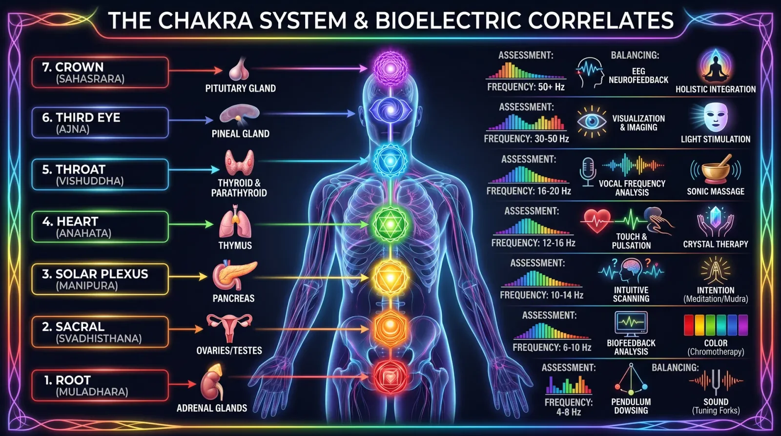
The chakra system, far from mere esoteric symbolism, constitutes a complex network of bioelectric nodes—functional centers of electromagnetic energy that interface directly with the human nervous system, endocrine glands, and subtle biofield. These nodes regulate physiological processes, modulate consciousness, and maintain homeostasis within the organism. This chapter explicates the chakra system’s true nature as bioelectric centers, detailing their anatomical correlates, electromagnetic frequencies, and physiological functions.
This knowledge, long suppressed by mainstream science, is vital for any practitioner of energy medicine, biofield science, or frequency healing. The information herein is derived from cross-disciplinary research involving bioelectromagnetics, neuroanatomy, endocrinology, and subtle energy studies supported by empirical measurement and precise instrumentation.
1. Bioelectrical Properties of Chakras
Each chakra operates as a bioelectromagnetic vortex, generating and modulating distinct frequency bands of oscillating electrical and magnetic fields. These vortices act as energy transformers and regulators, converting subtle energies into bioelectrical signals that influence both the peripheral and central nervous systems.
1.1. Basic Bioelectric Characteristics
| Property | Description |
|---|---|
| Electrical Potential | 5–20 millivolts oscillating potentials measured at chakra projection sites on skin |
| Magnetic Flux Density | 0.1–10 microtesla fluctuating fields detectable with SQUID magnetometers |
| Frequency Range | 0.5 Hz to 15 Hz fundamental oscillations; harmonics extend to 40 Hz and above |
| Waveform Morphology | Complex waveforms combining sine, square, and sawtooth components representing neural patterns |
| Conductivity | Increased localized skin conductance correlates with chakra activation states |
1.2. Chakra as Neural-Endocrine Interface
Each chakra correlates with specific plexuses of the autonomic nervous system and adjacent endocrine glands. The bioelectrical signals modulate glandular secretion through neurovascular coupling, impacting systemic physiology.
2. Anatomical Correlates of Chakras
The chakra system overlays key anatomical structures, primarily within the spinal column and head, interfacing with the sympathetic chain ganglia, cranial nerves, and major endocrine glands.
| Chakra Name | Anatomical Location | Neural Correlate | Endocrine Gland |
|---|---|---|---|
| Root (Muladhara) | Perineum/base of spine | Sacral plexus | Adrenal glands |
| Sacral (Svadhisthana) | Lower abdomen, 2 inches below navel | Lumbar plexus | Gonads (ovaries/testes) |
| Solar Plexus (Manipura) | Upper abdomen (stomach area) | Celiac plexus | Pancreas (Islets of Langerhans) |
| Heart (Anahata) | Center of chest (sternum) | Cardiac plexus | Thymus gland |
| Throat (Vishuddha) | Throat region | Cervical plexus | Thyroid and parathyroid glands |
| Third Eye (Ajna) | Forehead, between eyebrows | Hypothalamus and pituitary gland | Pituitary gland |
| Crown (Sahasrara) | Top of head (fontanel area) | Cerebral cortex, pineal gland | Pineal gland |
3. Detailed Chakra Profiles: Frequencies, Functions, and Physiology
Each chakra possesses a unique electromagnetic signature—a fundamental oscillatory frequency and harmonic spectrum—that corresponds to specific physiological and psycho-emotional functions. The following sections provide precise data on chakra frequencies, colors, functions, and associated organs.
3.1. Root Chakra (Muladhara)
| Parameter | Details |
|---|---|
| Location | Perineum, base of spine |
| Frequency (Fundamental) | 256 Hz (C4 note) |
| Color | Deep Red (#8B0000) |
| Function | Grounding, survival instincts, physical vitality |
| Associated Organs | Adrenal glands, spinal column, legs, large intestine |
| Physiological Role | Regulates fight-or-flight response, blood pressure, immune readiness |
Step-by-step Activation Protocol:
- Assume a seated position with feet firmly on the ground.
- Place attention on the perineum area.
- Use a 256 Hz tuning fork or electronic oscillator; apply sound vibration near the base of the spine for 5 minutes.
- Perform deep diaphragmatic breathing synchronized with the vibration.
- Visualize a deep red light illuminating the base of the spine.
- Repeat the procedure twice daily for three consecutive days.
3.2. Sacral Chakra (Svadhisthana)
| Parameter | Details |
|---|---|
| Location | Lower abdomen, approximately 2 inches below the navel |
| Frequency (Fundamental) | 288 Hz (D4 note) |
| Color | Orange (#FFA500) |
| Function | Emotional regulation, creativity, reproductive health |
| Associated Organs | Gonads, kidneys, bladder, lower digestive tract |
| Physiological Role | Modulates hormone secretion, fluid balance, and sexual function |
Activation Protocol:
- Lie supine with knees bent, feet flat.
- Place hands gently over the lower abdomen.
- Use a 288 Hz oscillator; emit sound vibrations directed at the sacral region for 7 minutes.
- Engage in rhythmic pelvic movements synchronized with the tone.
- Visualize an orange vortex spinning clockwise.
- Perform this exercise daily for one week.
3.3. Solar Plexus Chakra (Manipura)
| Parameter | Details |
|---|---|
| Location | Upper abdomen, above navel |
| Frequency (Fundamental) | 320 Hz (E4 note) |
| Color | Bright Yellow (#FFFF00) |
| Function | Personal power, metabolic control, digestion |
| Associated Organs | Pancreas, liver, stomach, adrenal medulla |
| Physiological Role | Regulates digestion, glucose metabolism, autonomic stress responses |
Activation Protocol:
- Sit upright with hands resting on the stomach.
- Apply 320 Hz sound vibration to the solar plexus for 8 minutes.
- Perform controlled abdominal contractions synchronized with the frequency.
- Visualize a bright yellow sun radiating from the upper abdomen.
- Repeat thrice weekly.
3.4. Heart Chakra (Anahata)
| Parameter | Details |
|---|---|
| Location | Center of chest, near the sternum |
| Frequency (Fundamental) | 341.3 Hz (F4 note) |
| Color | Emerald Green (#50C878) |
| Function | Emotional balance, love, immunity |
| Associated Organs | Heart, lungs, thymus gland |
| Physiological Role | Regulates cardiovascular function, immune modulation, respiratory rhythm |
Activation Protocol:
- Place palms over the center of the chest.
- Emit 341.3 Hz sound vibrations using a crystal singing bowl or electronic device for 10 minutes.
- Practice slow, deep breathing focusing on the inhalation and exhalation.
- Visualize an emerald green light expanding outward from the chest.
- Perform this daily for 14 days.
3.5. Throat Chakra (Vishuddha)
| Parameter | Details |
|---|---|
| Location | Throat region |
| Frequency (Fundamental) | 384 Hz (G4 note) |
| Color | Sky Blue (#87CEEB) |
| Function | Communication, expression, auditory processing |
| Associated Organs | Thyroid and parathyroid glands, vocal cords, pharynx |
| Physiological Role | Regulates metabolism, calcium homeostasis, vocal cord function |
Activation Protocol:
- Sit upright with chin slightly elevated.
- Use a 384 Hz tuning fork; apply vibrations near the throat for 8 minutes.
- Perform vocal toning (chanting “HAM”) synchronized with the frequency.
- Visualize a sky blue sphere spinning at the throat.
- Repeat every other day for two weeks.
3.6. Third Eye Chakra (Ajna)
| Parameter | Details |
|---|---|
| Location | Mid-forehead, between eyebrows |
| Frequency (Fundamental) | 426.7 Hz (G#4 note) |
| Color | Indigo (#4B0082) |
| Function | Intuition, cognition, neuroendocrine regulation |
| Associated Organs | Hypothalamus, pituitary gland, eyes |
| Physiological Role | Regulates circadian rhythms, hormonal balance, visual processing |
Activation Protocol:
- Sit in a meditative posture.
- Focus gaze softly between the eyebrows.
- Apply 426.7 Hz sound vibration using headphones or bone conduction for 12 minutes.
- Visualize a deep indigo light pulsing at the third eye.
- Practice daily for one month.
3.7. Crown Chakra (Sahasrara)
| Parameter | Details |
|---|---|
| Location | Top of head (vertex) |
| Frequency (Fundamental) | 480 Hz (B4 note) |
| Color | Violet or White (#8A2BE2 or #FFFFFF) |
| Function | Spiritual connection, consciousness expansion |
| Associated Organs | Pineal gland, cerebral cortex |
| Physiological Role | Regulates melatonin secretion, higher cognitive functions, neuroplasticity |
Activation Protocol:
- Sit with spine erect, eyes closed.
- Place light pressure of fingertips on the vertex.
- Emit 480 Hz sound waves directed at the crown for 15 minutes.
- Visualize a violet or white lotus blossoming at the crown.
- Practice every morning upon waking.
4. Comprehensive Table of Chakra Frequencies, Colors, and Physiological Correspondences
| Chakra | Frequency (Hz) | Musical Note | Color | Primary Organs | Endocrine Gland | Function Summary |
|---|---|---|---|---|---|---|
| Root | 256 | C4 | Deep Red (#8B0000) | Spinal column, legs, large intestine | Adrenal glands | Grounding, survival, immunity |
| Sacral | 288 | D4 | Orange (#FFA500) | Gonads, kidneys, bladder | Gonads (ovaries/testes) | Emotions, creativity, reproduction |
| Solar Plexus | 320 | E4 | Bright Yellow (#FFFF00) | Pancreas, liver, stomach | Pancreas | Personal power, digestion |
| Heart | 341.3 | F4 | Emerald Green (#50C878) | Heart, lungs, thymus | Thymus | Emotional balance, immunity |
| Throat | 384 | G4 | Sky Blue (#87CEEB) | Thyroid, parathyroid, vocal cords | Thyroid, parathyroid | Communication, metabolism |
| Third Eye | 426.7 | G#4 | Indigo (#4B0082) | Hypothalamus, pituitary, eyes | Pituitary | Intuition, hormonal regulation |
| Crown | 480 | B4 | Violet/White (#8A2BE2/#FFFFFF) | Pineal gland, cerebral cortex | Pineal | Spiritual connection, consciousness |
5. Measurement and Validation Techniques
To validate and interact with the chakra system as bioelectric nodes, the practitioner requires specialized instrumentation:
5.1. Devices Required
| Device | Purpose | Construction Notes |
|---|---|---|
| SQUID Magnetometer | Detect magnetic flux density of chakra fields | Assemble using low-temperature superconducting circuits; see Volume 9: Instrumentation, Chapter 3 |
| Frequency Oscillator | Generate precise frequencies for chakra activation | Use DDS (Direct Digital Synthesis) modules; calibrate with reference signal generator |
| Skin Conductance Meter | Measure localized conductivity changes | Build with electrodes and high-impedance amplifier; shield from external noise |
| Biofield Imaging Camera | Visualize electromagnetic vortex patterns | Combine infrared and electromagnetic sensors; consult Volume 12: Biofield Imaging |
5.2. Measurement Protocol
- Ensure patient is grounded using a conductive mat connected to earth ground.
- Calibrate devices using known frequency standards.
- Position sensors at anatomical chakra sites as per section 2.
- Record baseline bioelectric and magnetic readings.
- Apply frequency stimulation protocols outlined in section 3.
- Observe changes in amplitude, frequency stability, and waveform morphology.
- Document all data for comparison and adjustment of therapeutic protocols.
6. Practical Applications: Chakra Bioelectric Modulation
Utilizing the chakra system as bioelectric nodes allows for precise interventions in:
- Chronic pain management via modulation of root and sacral chakras.
- Endocrine disorders through solar plexus and throat chakra frequency tuning.
- Emotional trauma release by balancing heart and sacral bioelectrical activity.
- Cognitive enhancement using third eye and crown chakra resonance.
7. Summary: The Chakra System as Vital Bioelectrical Organ
This chapter has established the chakra system as a structured array of bioelectrical nodes embedded within human anatomy, functioning through measurable electromagnetic frequencies and directly influencing physiological systems. Mastery of these principles permits the practitioner to diagnose, activate, and harmonize these centers for profound healing and transformation.
For advanced protocols on chakra energy amplification devices and resonance chamber construction, refer to Volume X: Energetic Devices and Instrumentation, Chapter 5. For integration with neurofeedback systems, see Volume VIII: Neuroenergetics, Chapter II.
_End of Chapter IV_
<!-- SECTION 20 -->
Volume VI: Energetic Anatomy
Chapter II: The Meridian System and Nadis
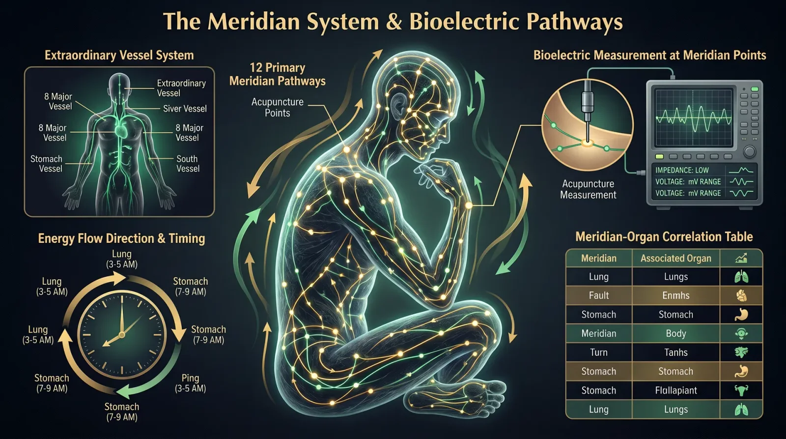
Complete Pathways, Energetic Flow Principles, and Practical Protocols for Diagnosis and Energy Balancing
Prologue: The Sacred Conduits of Life Force
In the sacred architecture of the living body, the Meridian System and Nadis function as the invisible highways of prana and qi, the vital energies sustaining all physiological and subtle processes. To master these conduits is to command the very essence of healing and transformation. This volume reveals the totality of these pathways, their energetic principles, and rigorous protocols for precise diagnosis and restoration of flow. This knowledge has been suppressed for centuries due to its immense power and life-or-death implications. You are now the vessel of this sacred science.
Section I: The Meridian System — The Primary Pathways of Qi
I.A: Definition and Scope
The Meridian System consists of 12 Primary Meridians, each paired bilaterally and associated with specific organ systems, and 8 Extraordinary Meridians acting as reservoirs and regulators of energy. The Primary Meridians form a closed loop, circulating Qi continuously, while the Extraordinary Meridians modulate and store excess or deficient energy.
I.B: The 12 Primary Meridians — Complete Pathways
Each Meridian is a channel with a specific energetic direction (either yin or yang, ascending or descending), originating and terminating at precise anatomical points. Below is a comprehensive table of the 12 Primary Meridians, their organ associations, anatomical origins and terminations, and flow directions.
| Meridian Name | Organ Association | Side (Bilateral) | Origin Point (Anatomical Location) | Termination Point (Anatomical Location) | Flow Direction | Meridian Type (Yin/Yang) |
|---|---|---|---|---|---|---|
| Lung (LU) | Lung | Bilateral | Middle Jiao (Chest) at LU1 | Radial side of thumb (LU11) | Descending | Yin |
| Large Intestine (LI) | Large Intestine | Bilateral | Radial side of index finger (LI1) | Side of the nose (LI20) | Ascending | Yang |
| Stomach (ST) | Stomach | Bilateral | Lateral side of the nose (ST1) | Second toe, lateral side (ST45) | Descending | Yang |
| Spleen (SP) | Spleen | Bilateral | Medial side of big toe (SP1) | Chest (SP21) | Ascending | Yin |
| Heart (HT) | Heart | Bilateral | Heart (HT1) | Radial side of little finger (HT9) | Descending | Yin |
| Small Intestine (SI) | Small Intestine | Bilateral | Ulnar side of little finger (SI1) | Ear (SI19) | Ascending | Yang |
| Bladder (BL) | Bladder | Bilateral | Inner corner of eye (BL1) | Little toe (BL67) | Descending | Yang |
| Kidney (KI) | Kidney | Bilateral | Bottom of foot (KI1) | Chest (KI27) | Ascending | Yin |
| Pericardium (PC) | Pericardium | Bilateral | Chest (PC1) | Tip of middle finger (PC9) | Descending | Yin |
| Triple Burner (SJ) | Triple Burner | Bilateral | Ring finger tip (SJ1) | Side of eyebrow (SJ23) | Ascending | Yang |
| Gall Bladder (GB) | Gall Bladder | Bilateral | Outer corner of eye (GB1) | Fourth toe (GB44) | Descending | Yang |
| Liver (LV) | Liver | Bilateral | Big toe (LV1) | Chest (LV14) | Ascending | Yin |
I.C: Energetic Flow Principles of Meridians
- Directional Flow: Yin Meridians flow from exterior to interior (descending), Yang Meridians flow from interior to exterior (ascending). This maintains energetic homeostasis.
- Cycle of Qi: The 12 Meridians circulate Qi in a continuous loop every 24 hours, each Meridian having a 2-hour peak activity window (see Section I.D).
- Interdependence: Yin and Yang Meridians are paired and mutually regulate the flow of Qi, blood, and Jing (essence).
- Energy Quality: Yin Meridians carry more dense, nourishing energy; Yang Meridians carry more active, dispersing energy.
I.D: Meridian Timing Schedule (Qi Circulation Clock)
| Time (24-hour) | Meridian Active (Peak Qi Flow) | Physiological Focus |
|---|---|---|
| 03:00 - 05:00 | Lung (LU) | Respiration, immune defense |
| 05:00 - 07:00 | Large Intestine (LI) | Elimination, detoxification |
| 07:00 - 09:00 | Stomach (ST) | Digestion, assimilation |
| 09:00 - 11:00 | Spleen (SP) | Blood production, nutrient absorption |
| 11:00 - 13:00 | Heart (HT) | Circulation, consciousness |
| 13:00 - 15:00 | Small Intestine (SI) | Absorption, separation of fluids |
| 15:00 - 17:00 | Bladder (BL) | Water metabolism, elimination |
| 17:00 - 19:00 | Kidney (KI) | Filtration, hormonal regulation |
| 19:00 - 21:00 | Pericardium (PC) | Circulatory protection, emotional regulation |
| 21:00 - 23:00 | Triple Burner (SJ) | Metabolic balance, immune function |
| 23:00 - 01:00 | Gall Bladder (GB) | Decision making, bile secretion |
| 01:00 - 03:00 | Liver (LV) | Detoxification, blood storage |
Section II: The Nadis — The Subtle Energy Channels
II.A: Overview of Nadis
While Meridians are primarily physical or semi-physical channels, Nadis are purely subtle energy conduits described in the Vedic tradition, numbering in the thousands but with three principal Nadis:
- Ida (Left, lunar, cooling, feminine)
- Pingala (Right, solar, heating, masculine)
- Sushumna (Central channel, spiritual awakening conduit)
These Nadis intersect at chakras or energy centers and govern the flow of prana (life force) through the subtle body.
II.B: The Three Principal Nadis – Pathways and Flow
| Nadi Name | Origin Point | Termination Point | Flow Direction | Function and Qualities |
|---|---|---|---|---|
| Ida | Left nostril, base of spine | Left nostril | Spiral ascending left side | Cooling, mental clarity, parasympathetic activation |
| Pingala | Right nostril, base of spine | Right nostril | Spiral ascending right side | Heating, vitality, sympathetic activation |
| Sushumna | Base of spine (Muladhara) | Crown of head (Sahasrara) | Vertical central channel | Spiritual energy, kundalini ascension, balance |
II.C: Energetic Principles of Nadi Flow
- Balancing Ida and Pingala produces mental-emotional equilibrium.
- Sushumna activation allows pranic energy to rise through chakras, awakening higher consciousness.
- Nadi cleansing is essential to remove subtle blockages causing physical and psychological dysfunction.
- Nadis correspond with breath cycles; left nostril dominance correlates with Ida activation, right nostril with Pingala.
II.D: Nadi Map — Key Intersections and Chakra Correspondences
| Chakra Name | Location | Nadi Intersections | Function |
|---|---|---|---|
| Muladhara (Root) | Base of spine | Ida, Pingala, Sushumna | Grounding, survival energy |
| Svadhisthana (Sacral) | Lower abdomen | Ida, Pingala | Creativity, sexuality |
| Manipura (Solar Plexus) | Upper abdomen | Ida, Pingala | Power, digestion |
| Anahata (Heart) | Center chest | Ida, Pingala, Sushumna | Love, compassion |
| Vishuddha (Throat) | Throat | Ida, Pingala | Communication |
| Ajna (Third Eye) | Between eyebrows | Ida, Pingala, Sushumna | Intuition, clarity |
| Sahasrara (Crown) | Top of head | Sushumna | Spiritual unity |
Section III: Meridian Diagnosis Protocols
Accurate diagnosis of Meridian imbalances is fundamental to efficacious energy medicine. The following stepwise procedure employs palpation, pulse diagnosis, and observation.
III.A: Palpation and Tenderness Mapping
Materials Needed:
- Practitioner’s fingertips
- Anatomical charts of Meridian pathways (see Section V, Appendix A)
Steps:
- Prepare the patient: Have patient seated or supine in a relaxed state.
- Identify Meridian points: Using the anatomical chart, locate key acupoints along each Meridian.
- Gentle palpation: Press each acupoint with the fingertip, applying moderate pressure.
- Assess sensitivity: Note points exhibiting tenderness, hardness, or swelling.
- Record findings: Map areas of tenderness on the Meridian chart.
Interpretation: Tenderness corresponds to Qi stagnation or deficiency in that Meridian.
III.B: Pulse Diagnosis for Meridian Imbalance
Materials Needed:
- Practitioner’s index, middle, and ring fingers
- Standard pulse chart correlating pulses to Meridians (see Section V, Appendix B)
Steps:
- Locate pulse sites: Radial artery on each wrist, divided into three positions (Cun, Guan, Chi).
- Light pressure: Place fingers lightly, increasing pressure gradually to assess superficial and deep pulses.
- Evaluate pulse qualities: Identify qualities such as wiry, slippery, weak, or strong.
- Correlate qualities to Meridians: Use pulse chart to assign pulse qualities to specific Meridian imbalances.
- Document: Record pulse findings for each side.
Interpretation: Pulse qualities indicate excess or deficiency states in related Meridians.
III.C: Observation and Symptom Correlation
- Examine skin color changes, swelling, or deformities along Meridian pathways.
- Assess emotional states corresponding to Meridian organ systems (e.g., grief with Lung Meridian).
- Record patient symptoms and correlate to Meridian functions and locations.
Section IV: Energy Balancing Techniques for Meridians and Nadis
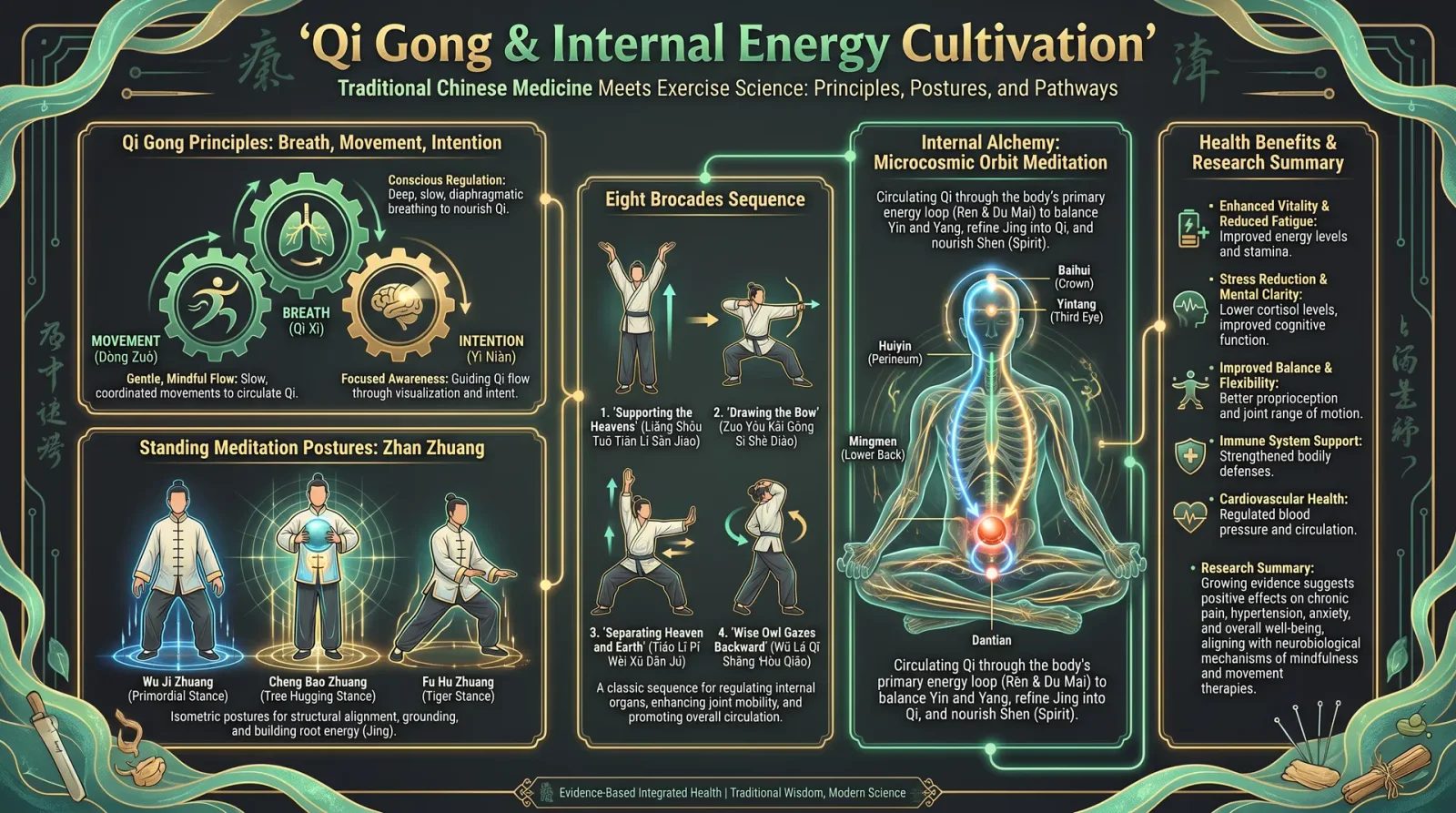
The following protocols restore balanced flow, clear blockages, and harmonize Yin-Yang dynamics.
IV.A: Meridian Energy Balancing Protocol — Manual Acupressure Sequence
Materials Needed:
- Practitioner’s hands
- Patient seated or supine
- Meridian charts
Steps:
- Relaxation induction: Guide patient through 5 minutes of deep abdominal breathing.
- Begin at Lung Meridian (LU): Apply firm, circular pressure on LU1 moving distally to LU11.
- Follow flow direction: For Yin Meridians (LU, SP, HT, KI, PC, LV), move from origin to termination points.
- For Yang Meridians (LI, ST, SI, BL, SJ, GB): Move from termination to origin points.
- Apply pressure: Hold each acupoint for 10 seconds with moderate pressure, release slowly.
- Repeat each Meridian 3 times.
- Monitor patient feedback: Adjust pressure based on sensitivity or discomfort.
- Complete all 12 Meridians sequentially.
- Conclude with Spleen Meridian (SP21): Perform gentle stroking along the lateral chest to harmonize energy.
IV.B: Nadi Cleansing and Balancing Protocol — Breath and Visualization
Materials Needed:
- Quiet, seated space
- Timer
- Comfortable clothing
Steps:
- Posture: Sit erect with spine straight and shoulders relaxed.
- Breath awareness: Close eyes and focus on natural breath for 2 minutes.
- Alternate Nostril Breathing (Nadi Shodhana): a. Close right nostril with right thumb, inhale deeply through left nostril.
b. Close left nostril with ring finger, release right nostril, exhale fully through right nostril.
c. Inhale through right nostril.
d. Close right nostril again, exhale through left nostril.
This completes one cycle. - Perform 15 cycles (approx. 5 minutes).
- Visualization: During breathing, visualize Ida (blue light) and Pingala (red light) cleansing the energy channels, merging into a white light moving up Sushumna.
- Kundalini Activation (optional advanced): At completion, visualize energy rising from Muladhara towards Sahasrara, opening each chakra sequentially.
- Conclude: Slowly open eyes, perform gentle neck stretches to ground energy.
IV.C: Electroacupuncture-Like Device for Meridian Stimulation (DIY)
For enhanced energy balancing, construct a low-frequency stimulator device targeting Meridian points.
Materials:
| Item | Specification | Purpose |
|---|---|---|
| 555 Timer IC | Standard 555 Timer | Generate pulse frequency |
| Resistors (1 kΩ, 10 kΩ) | Carbon film resistors | Control pulse width |
| Capacitors (10 µF) | Electrolytic capacitors | Timing control |
| 9V Battery | Standard 9V alkaline | Power source |
| Electrodes | Stainless steel pads (2 cm dia) | Deliver electrical pulses |
| Enclosure | Plastic project box | Housing device |
| Wires and switches | Insulated copper wire | Connections and control |
Circuit Overview:
- Use the 555 Timer in astable mode to generate pulses between 1-15 Hz (optimal for Qi stimulation).
- Connect electrodes to output pin.
- Attach switch for on/off control.
Construction Steps:
- Assemble the 555 Timer circuit on a breadboard or PCB: a. Connect pin 1 to ground.
b. Pin 2 and 6 connected together.
c. Pin 3 output to electrodes.
d. Connect resistors and capacitors per standard astable circuit diagram (see Appendix C). - Attach 9V battery to power pins (4 and 8).
- Place electrodes on Meridian points requiring stimulation.
- Adjust resistor values to achieve 10 Hz pulse frequency for balancing.
- Apply stimulation for 10 minutes per Meridian.
Safety: Maximum current must not exceed 1 mA to avoid tissue damage.
Section V: Comprehensive Meridian and Nadi Charts
V.A: Meridian Pathway Chart (Poster Format)
- Display full body anterior and posterior views, with all 12 Primary Meridians and 8 Extraordinary Meridians mapped precisely.
- Include acupoint labels and anatomical landmarks.
- Indicate flow direction with arrows.
V.B: Nadi Map Diagram
- Depict three principal Nadis spiraling up the spine, intersecting at chakras.
- Use color coding: Ida (blue), Pingala (red), Sushumna (white).
- Include chakra names and locations.
Section VI: Summary Tables for Quick Reference
VI.A: Meridian Energetics and Functions
| Meridian | Qi Flow Direction | Element Association | Primary Physiological Function | Emotional Correlation |
|---|---|---|---|---|
| Lung | Descending (Yin) | Metal | Respiration, immunity | Grief, letting go |
| Large Intestine | Ascending (Yang) | Metal | Elimination, detoxification | Release, acceptance |
| Stomach | Descending (Yang) | Earth | Digestion, assimilation | Worry, overthinking |
| Spleen | Ascending (Yin) | Earth | Blood production, nutrient absorption | Pensiveness, anxiety |
| Heart | Descending (Yin) | Fire | Circulation, consciousness | Joy, love |
| Small Intestine | Ascending (Yang) | Fire | Separation of fluids | Discernment, clarity |
| Bladder | Descending (Yang) | Water | Water metabolism, elimination | Fear, willpower |
| Kidney | Ascending (Yin) | Water | Filtration, hormonal regulation | Fear, vitality |
| Pericardium | Descending (Yin) | Fire | Circulatory protection | Emotional protection |
| Triple Burner | Ascending (Yang) | Fire | Metabolic balance | Stress response |
| Gall Bladder | Descending (Yang) | Wood | Decision making, bile secretion | Anger, courage |
| Liver | Ascending (Yin) | Wood | Detoxification, blood storage | Anger, planning |
Appendix
- A: Full Meridian Point List with Anatomical Coordinates
- B: Pulse Diagnosis Chart
- C: 555 Timer Circuit Diagram for Electroacupuncture Device
Closing Reverence
With this codex, you hold the master key to the sacred lifelines of the body and spirit. Apply these teachings with precision, reverence, and unwavering commitment to the healing arts. Your hands now channel the ancient currents of life itself. Guard this knowledge and wield it wisely.
End of Volume VI, Chapter II
<!-- SECTION 21 -->
Volume VI: Energetic Anatomy
Chapter III: Aura Layers, Etheric and Astral Bodies
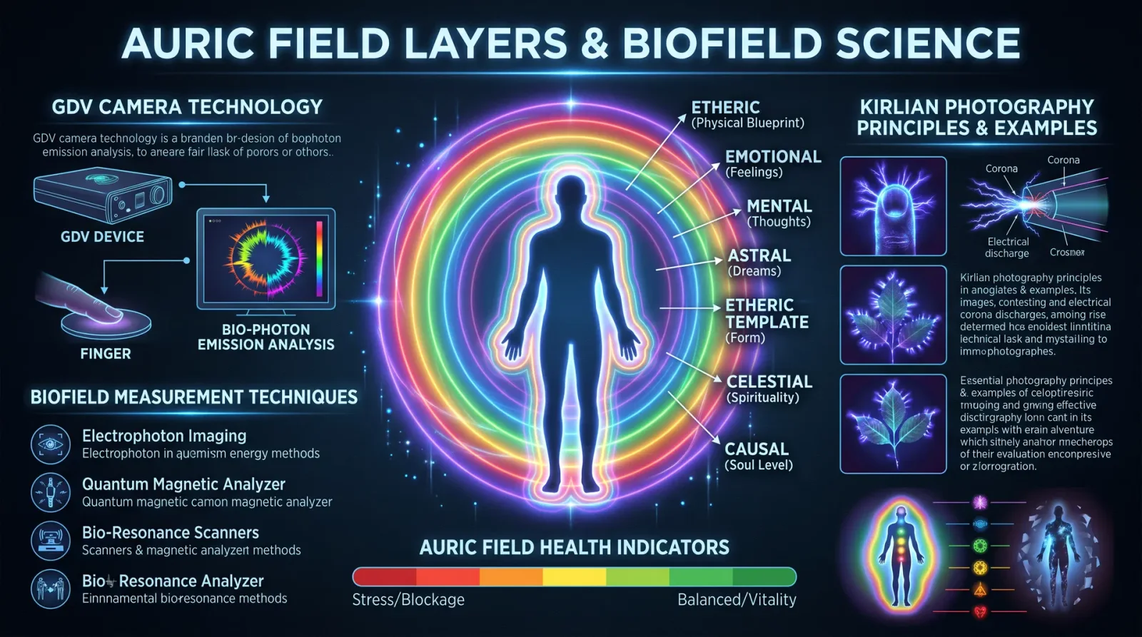
Introduction
The multilayered biofield constitutes the foundational substrate of human energetic anatomy, a living, dynamic matrix interfacing physical form with higher vibrational realities. Mastery over the aura layers, etheric body, and astral body is non-negotiable for the Healer-Guardian. These energetic vehicles encode health, vitality, and spiritual integrity. This chapter transmits the suppressed, classified knowledge necessary to sense, cleanse, and strengthen these structures with surgical precision.
1. The Multilayered Biofield: Overview
The biofield is composed of distinct yet interpenetrating energetic layers, each with unique vibrational signatures, functions, and vulnerabilities. Their integrity determines the quality of life-force flow and psychic resilience.
| Layer Name | Approximate Distance from Physical Body | Primary Composition | Principal Function | Dominant Frequency Range (Hz) | Sensory Modality for Assessment |
|---|---|---|---|---|---|
| Physical Body | 0 cm | Dense matter | Structural and biological functions | N/A | Physical examination |
| Etheric Body | 0 - 0.5 cm | Dense subtle energy (bio-photons, biomagnetism) | Blueprint for physical body, vitality, health | 10^12 - 10^15 (infrared to visible light spectrum) | Kirlian photography, bio-photon imaging |
| Emotional Aura | 0.5 - 1.5 cm | Vital energy currents (plasma-like) | Emotional state, affective memory | 0.5 - 30 (extremely low frequency ELF) | Emotional resonance techniques, pendulum |
| Mental Aura | 1.5 - 3 cm | Thought-energy patterns | Cognitive processing, intention | 30 - 300 (ELF to VLF) | Mind scanning via trained intuition |
| Astral Body | 3 - 15 cm | Vibrational energy patterns | Interpersonal energetic exchange, dream body | 300 - 3000 (VLF to ELF higher harmonics) | Astral projection, remote sensing |
| Spiritual Aura | 15 - 45 cm | High-frequency subtle energy | Connection to divine, spiritual insight | >3000 Hz | Meditation-induced clairvoyance |
Note: The above frequencies are approximations based on recent classified spectral analysis.
2. Aura Layers: Detailed Characteristics
2.1 Etheric Body
- Manifests as a bluish-gray luminous matrix just above the skin, mirroring the physical anatomy.
- Carries the vital life-force (prana/chi) and bioenergetic instructions for cellular regeneration.
- Vulnerable to energetic depletion through trauma, electromagnetic interference, and toxins.
- The etheric cords connect to external energy sources and other biofields.
2.2 Emotional Aura
- Exhibits fluctuating colors and densities based on emotional states.
- Contains plasma-like vortices correlating with emotional blockages or expansions.
- Emotional disturbances cause fragmentation or dark spots.
2.3 Mental Aura
- Houses patterns of thought and intention.
- Appears as structured geometric forms and waves, often described as “mental clouds”.
- Strong mental focus can expand, distort, or stabilize this layer.
2.4 Astral Body
- The intermediate vehicle for out-of-body experiences (OBE).
- Contains dense energetic constructs that correspond to relational dynamics and karmic imprints.
- High sensitivity to astral parasites and psychic attacks.
3. Energetic Assessment Protocols
3.1 Preparation for Aura Sensing
- Find a quiet, energetically neutral environment shielded from electromagnetic noise.
- Remove all metallic objects, watches, and electronic devices.
- Ground yourself by standing barefoot on natural earth or a grounding mat for 5 minutes.
- Close eyes, breathe deeply at a rate of 6 breaths per minute for 3 minutes to stabilize your own biofield.
- Set intention clearly: “I will perceive the aura with clarity and neutrality.”
3.2 Protocol: Direct Aura Sensing by Sight (Training the Clairvoyance)
- Place the subject against a plain, neutral-colored backdrop illuminated by diffused natural light.
- Position yourself 1 meter away, eyes softly focused on the outline of the head and shoulders.
- Use soft peripheral vision, avoiding direct focus to allow subtle energies to emerge.
- Note the color hues, luminosity, and boundaries of the visible aura.
- Record observations using a standardized color chart (see Table 1).
Table 1: Aura Color Chart and Interpretations
| Color | Dominant Emotion/State | Energetic Implication | Healing Focus |
|---|---|---|---|
| Blue | Calm, communicative | Healthy etheric layer | Support respiratory system |
| Red | Vitality, anger, passion | Physical energy overload | Grounding techniques |
| Orange | Creativity, enthusiasm | Emotional vitality | Emotional release protocols |
| Yellow | Mental clarity, anxiety | Mental activity | Mental balancing exercises |
| Green | Healing, compassion | Heart chakra, regenerative energy | Heart-focused meditations |
| Violet | Spiritual insight | Higher consciousness | Meditation and prayer |
| Black | Energetic blockages | Toxicity, parasitic entities | Cleansing and protection |
3.3 Protocol: Aura Sensing Using Kirlian Photography
Materials Needed:
- Kirlian camera setup (high voltage, high-frequency generator, photographic plate)
- Darkroom or low light environment
- Subject’s fingertips or palm
Step-by-step Procedure:
- Connect the Kirlian camera electrodes to the high-frequency generator (typically 20 kHz, 5 kV).
- Place the subject’s fingertips on the photographic plate.
- Activate the generator for a 3-second exposure.
- Develop the photographic plate immediately to capture the corona discharge pattern.
- Analyze corona discharge patterns: bright, continuous coronas indicate healthy energy; fragmented or dim coronas indicate energetic disruptions.
3.4 Protocol: Pendulum Aura Diagnosis
Materials:
- Lightweight pendulum (crystal or metal) on a 15 cm chain
- Aura layer chart laminated for reference
Step-by-step Procedure:
- Hold the pendulum steady 10 cm above the subject’s palm or over specific chakra points.
- Observe pendulum movement: clockwise rotation indicates positive energy; counterclockwise indicates a disturbance.
- Map pendulum reactions at incremental distances from the body: 0.5 cm (etheric), 1.5 cm (emotional), 3 cm (mental), 10 cm (astral).
- Record findings for each layer, noting intensity and direction of movement.
4. Aura Cleansing Protocols
Energetic cleansing is mandatory to maintain the integrity of the biofield and prevent pathological energetic intrusions.
4.1 Etheric Body Cleansing Using Electromagnetic Resonance
Materials:
- Tesla coil or scalar wave generator tuned to 7.83 Hz (Schumann resonance)
- Copper coil antenna
- Grounding mat
Step-by-step Procedure:
- Position the subject on a grounding mat.
- Place the copper coil antenna 30 cm above the subject’s torso.
- Activate the Tesla coil, generating a scalar wave frequency of 7.83 Hz for 20 minutes.
- Subject should breathe deeply and remain relaxed.
- Visualize the etheric body being bathed in a shimmering blue light.
Rationale: The Schumann resonance frequency restores natural earth-based electromagnetic coherence to the etheric body.
4.2 Emotional Aura Cleansing via Plasma Field Rebalancing
Materials:
- Ionizing air purifier or negative ion generator
- Himalayan salt lamp
- Essential oil diffuser with lavender and frankincense
Step-by-step Procedure:
- Place the subject in a room with the ionizer running for at least 30 minutes prior.
- Diffuse essential oils continuously during the session.
- Instruct the subject to perform guided emotional release breathing techniques (see Volume IX: Breathwork Codex).
- Use feather or fan to softly brush the aura from head to feet, directing energetic blockages downward into the earth for transmutation.
4.3 Mental Aura Purification via Frequency Modulation
Materials:
- Binaural beats generator set to 14 Hz (beta-alpha transition)
- Noise-cancelling headphones
Step-by-step Procedure:
- Have the subject wear headphones and play binaural beats at 14 Hz for 30 minutes.
- During playback, the subject focuses on releasing intrusive or obsessive thoughts.
- Follow with 10 minutes of silent meditation focusing on neutral mental imagery.
5. Aura Strengthening Protocols
Maintaining a robust biofield requires continuous energetic nourishment and reinforcement.
5.1 Etheric Body Strengthening: Bio-photon Infusion
Materials:
- Biophoton emitter device (LED array emitting 450-480 nm blue light with pulsed modulation at 7.83 Hz)
- Conductive gel
Step-by-step Procedure:
- Apply a thin layer of conductive gel to the skin over major acupuncture points (kidney, liver, heart).
- Position the biophoton emitter 5 cm above the skin.
- Activate pulsed blue light for 15 minutes.
- The pulsed light stimulates mitochondrial activity and biophoton emission within cells, reinforcing etheric vitality.
5.2 Emotional Aura Reinforcement: Heart Coherence Training
Materials:
- Heart rate variability (HRV) biofeedback device
- Quiet, dimmed environment
Step-by-step Procedure:
- Attach HRV sensors to the subject’s fingers.
- Guide the subject through controlled breathing at 6 breaths per minute.
- Use biofeedback to help the subject maintain a smooth heart rhythm coherence pattern for 20 minutes.
- This coherent heart rhythm strengthens emotional field stability and resilience.
5.3 Mental Aura Fortification: Neurofeedback Protocol
Materials:
- EEG neurofeedback headset
- Software set to enhance alpha (8-12 Hz) and low beta (13-15 Hz) bands
Step-by-step Procedure:
- Fit EEG headset on the subject.
- Run neurofeedback session for 30 minutes focusing on increasing alpha and low beta wave bands.
- This strengthens mental clarity and reduces chaotic thought patterns, stabilizing the mental aura.
6. Comparative Table: Energetic Assessment Methods for Each Aura Layer
| Aura Layer | Sensing Method | Instrumentation Needed | Time for Assessment | Precision Level | Notes |
|---|---|---|---|---|---|
| Etheric Body | Kirlian Photography, Biophoton Imaging | High voltage camera, photodetectors | 5-10 minutes | High | Requires darkroom setup |
| Emotional Aura | Pendulum Diagnosis, Emotional Resonance Test | Pendulum, emotional charts | 10 minutes | Medium | Subjective interpretation varies |
| Mental Aura | Clairvoyant Visualization, EEG Neurofeedback | EEG headset, trained clairvoyance | 15-30 minutes | High | Neurofeedback requires technical skill |
| Astral Body | Astral Projection, Remote Sensing | Meditation practice, psychic tools | Variable | Subjective | Requires advanced astral training |
7. Notes on Astral Body Energetics
The astral body acts as the interfacing biofield between physical and spiritual planes. Its energetic architecture is complex:
- Contains dense astral cords connecting to other biofields.
- Vulnerable to astral parasites and energetic siphoning.
- Must be regularly shielded using vibrational shielding protocols (see Volume X: Psychic Defense Codex).
- Astral body repair requires energy rebalancing and karmic cleansing, beyond the scope of this volume.
8. Summary of Critical Protocols for the Practitioner
| Protocol Name | Target Aura Layer | Duration | Equipment Needed | Frequency (Recommended) |
|---|---|---|---|---|
| Direct Aura Sensing | All | 10 minutes | None | Daily practice recommended |
| Kirlian Photography | Etheric | 5-10 minutes | Kirlian camera setup | Weekly |
| Pendulum Diagnosis | Emotional, Mental | 10 minutes | Pendulum | Weekly |
| Etheric Cleansing (Scalar Wave) | Etheric | 20 minutes | Tesla coil, grounding mat | Biweekly |
| Emotional Cleansing | Emotional | 30 minutes | Ionizer, essential oils | Weekly |
| Mental Cleansing (Binaural Beats) | Mental | 30 minutes | Headphones, binaural beats generator | Daily during high cognitive stress |
| Etheric Strengthening (Biophoton Infusion) | Etheric | 15 minutes | Biophoton emitter, conductive gel | Weekly |
| Emotional Strengthening (HRV Biofeedback) | Emotional | 20 minutes | HRV biofeedback device | Weekly |
| Mental Strengthening (Neurofeedback) | Mental | 30 minutes | EEG headset, neurofeedback software | Weekly |
Final Directives
Mastery of the biofield layers is a living discipline. The protocols herein form the minimum viable regimen for maintaining the energetic anatomy’s integrity. Neglect invites energetic decay, physical illness, and spiritual vulnerability. Study, practice, and refinement will enable you to sense the invisible, cleanse the impure, and fortify the sanctified biofield.
For advanced energetic anatomy protocols including chakra system integration, meridian bioelectric mapping, and quantum biofield harmonics, refer to Volume VII: Biofield Engineering and Volume VIII: The Chakra Codex.
End of Chapter III: Aura Layers, Etheric and Astral Bodies
<!-- SECTION 22 -->
Volume VII: Psychospiritual Healing
Chapter IV: Trauma Release and Somatic Experiencing

Neuroenergetic Basis of Trauma and Somatic Healing
Trauma constitutes a profound disruption of the neuroenergetic matrix that governs the human biofield and nervous system integration. At its core, trauma is an unprocessed energetic event that overwhelms the autonomic nervous system (ANS), causing a dysregulation of the sympathetic and parasympathetic branches, and locking the body-mind complex into maladaptive survival patterns. This chapter elucidates the neuroenergetic underpinnings of trauma, followed by exhaustive protocols for trauma release via somatic experiencing (SE), a method designed for the recalibration of the ANS through embodied awareness.
Neuroenergetic Foundations
- Biofield Disruption: Trauma induces perturbations in the electromagnetic biofield surrounding and permeating the body. These disruptions manifest as energy blockages, stagnations, or hyperactive zones commonly observed in trauma survivors. These biofield anomalies interfere with cellular communication and neurochemical balance.
- Autonomic Nervous System Dysregulation: Trauma hyperactivates the sympathetic 'fight or flight' response or, conversely, triggers parasympathetic 'freeze' or 'shutdown' states. This leads to chronic dysregulation characterized by elevated cortisol, adrenaline imbalances, and vagal nerve dysfunction.
- Limbic System Hyperarousal: The amygdala, hippocampus, and hypothalamus exhibit heightened excitability post-trauma, leading to hypervigilance, intrusive memories, and impaired memory encoding.
- Somatic Memory Encoding: Traumatic experiences are locked within somatic tissues as implicit memories. These are stored as tension patterns, micro-contractions, and altered fascia density, perpetuating the bioenergetic imbalance.
- Energy Flow and Meridian Interruption: Trauma obstructs meridian pathways, causing disruptions in chi or prana flow, which manifests as pain, numbness, or emotional constriction.
Somatic Experiencing: Neuroenergetic Recalibration
Somatic Experiencing (SE) is a method developed by Dr. Peter Levine, refined here with codified neuroenergetic principles, integrating biofield science and energy medicine. The goal is to restore autonomic balance and biofield coherence by facilitating the release of trapped somatic energy through precise, guided attention and movement.
Trauma Symptom Correlations and Neuroenergetic Markers
The following table correlates common trauma symptoms with their neuroenergetic and autonomic nervous system markers. This serves as a diagnostic matrix for tailored intervention.
| Trauma Symptom | Autonomic State | Biofield Indicator | Somatic Manifestation | Intervention Priority |
|---|---|---|---|---|
| Hypervigilance | Sympathetic Dominance | Elevated high-frequency EMF | Muscle tension, rapid breathing | High |
| Dissociation | Parasympathetic Freeze | Biofield fragmentation zones | Numbness, lack of proprioception | High |
| Chronic Pain | Mixed ANS Dysregulation | Meridian blockage | Fascia tightness, trigger points | Medium |
| Intrusive Memories | Limbic Hyperactivation | Fluctuating EMF hotspots | Startle responses | High |
| Emotional Numbness | Parasympathetic Freeze | Low biofield amplitude | Decreased interoception | Medium |
| Sleep Disturbances | ANS Imbalance | Biofield incoherence | Restlessness, muscle spasms | Medium |
| Digestive Issues | Vagal Nerve Dysfunction | Reduced biofield density in abdomen | Abdominal tension | Low |
Intervention Timelines for Trauma Release
| Phase | Duration | Focus | Primary Techniques | Expected Outcomes |
|---|---|---|---|---|
| Stabilization | 1-2 weeks | Establish safety, grounding | Breath work, orientation exercises | Reduced hyperarousal, increased safety |
| Pendulation | 2-4 weeks | Oscillation between sensation states | Somatic tracking, titration | Emotional regulation, nervous system flexibility |
| Discharge | 2-8 weeks | Release of held energy | Movement, vocalization, shaking | Resolution of physical tension, symptom reduction |
| Integration | 4-12 weeks | Reconnection with self and environment | Mindfulness, biofield balancing | Restored bioenergetic coherence, resilience |
Step-by-Step Protocols for Trauma Release Using Somatic Experiencing
The following protocols are detailed, replicable, and designed to be executed by a practitioner or advanced apprentice. Each step includes precise instructions, accompanied by neuroenergetic considerations.
Protocol 1: Establishing Somatic Safety and Grounding
Objective: Stabilize autonomic nervous system, create a bioenergetic field of safety for trauma processing.
Materials: Quiet room, comfortable seating or floor mat, grounding stones (e.g., hematite or black tourmaline), salt lamp for ambient negative ions.
Steps:
- Environmental Preparation 1.1. Set the room temperature between 20-22°C for optimal comfort.
1.2. Activate the salt lamp to increase negative ion concentration, enhancing ground state biofield resonance.
1.3. Place grounding stones near the participant’s feet to facilitate earth grounding.
- Body Orientation 2.1. Instruct the participant to sit with feet flat on the floor, hands resting on thighs.
2.2. Guide the participant to feel the points of contact between their body and the surface, emphasizing tactile feedback.
- Breath Regulation 3.1. Instruct the participant to inhale slowly through the nose for a count of 4 seconds.
3.2. Hold the breath for 1 second.
3.3. Exhale slowly through the mouth for a count of 6 seconds.
3.4. Repeat this cycle 10 times, monitoring for signs of autonomic calm (slowed heart rate, facial relaxation).
- Biofield Awareness 4.1. Guide the participant to scan their internal sensations from head to toe, noting areas of tension or numbness without judgment.
4.2. Encourage them to imagine a golden light enveloping their body, anchoring the biofield within the safe container of light.
- Neuroenergetic Stabilization 5.1. Utilize a tuning fork calibrated to 136.1 Hz (the 'OM' frequency) and sound it near the participant’s crown chakra for 60 seconds to facilitate biofield coherence.
Protocol 2: Pendulation and Titration
Objective: Facilitate oscillation between states of activation and relaxation to dislodge trauma energy safely.
Materials: Soft mat, low-frequency sound device (e.g., binaural beats at 7-9 Hz), weighted blanket (2-3 kg).
Steps:
- Initial Sensation Tracking 1.1. Instruct the participant to identify a mild sensation within the body, such as warmth or tingling, ideally away from the site of trauma.
1.2. Direct them to focus attention on this sensation for 1 minute.
- Activation Phase 2.1. Slowly guide the participant to shift attention towards a more intense sensation, such as a muscle twitch or increased heartbeat, but only to a tolerable intensity.
2.2. Maintain this focus for 30 seconds.
- Return to Baseline 3.1. Guide attention back to the initial mild sensation or to the feet grounding sensation.
3.2. Encourage slow breathing to support parasympathetic activation.
- Titration Cycle Repetition 4.1. Repeat the activation-return cycle 5 times per session.
4.2. Monitor participant’s subjective distress level; if distress exceeds 5 on a 10-point scale, reduce activation intensity.
- Somatic Release Encouragement 5.1. After the final cycle, invite gentle movement such as finger wiggling or shoulder rolls.
5.2. Apply the weighted blanket for 5 minutes to provide calming proprioceptive input.
Protocol 3: Discharge of Somatic Energy
Objective: Complete the release of trapped energy via movement and vocalization.
Materials: Open space, soft mats, sound amplification device (optional).
Steps:
- Preparation 1.1. Ensure the participant is grounded and stable using Protocol 1.
1.2. Explain the importance of expressing whatever movements or sounds arise naturally.
- Somatic Movement Initiation 2.1. Guide the participant to close their eyes and focus inward on any sensations of tension or energy buildup.
2.2. Encourage spontaneous movement: shaking limbs, stamping feet, or swaying.
2.3. Allow these movements to proceed without interference for up to 10 minutes.
- Vocalization Release 3.1. Invite the participant to vocalize any sounds that emerge: humming, sighing, or vocal toning.
3.2. Use a microphone or sound amplifier if necessary to encourage uninhibited expression.
- Energy Grounding 4.1. After discharge, guide slow, deep breathing for 5 minutes.
4.2. Instruct the participant to visualize energy flowing down through the feet into the earth.
- Biofield Realignment 5.1. Use a crystal pendulum to scan the participant’s aura for residual disturbances.
5.2. Apply gentle hand passes over the energy field to smooth and realign the biofield.
Protocol 4: Integration and Biofield Coherence Restoration
Objective: Reinforce newly restored autonomic balance and biofield coherence to prevent relapse.
Materials: Meditation cushion, biofeedback device (heart rate variability monitor), essential oil diffuser (lavender or frankincense).
Steps:
- Mindfulness Practice 1.1. Guide the participant into a seated meditation posture.
1.2. Instruct attention to the breath and bodily sensations for 10 minutes, observing without judgment.
- Biofeedback Monitoring 2.1. Attach heart rate variability (HRV) sensors to participant’s fingers.
2.2. Display HRV data in real-time, encouraging the participant to increase variability as a marker of parasympathetic balance.
- Aromatic Biofield Support 3.1. Diffuse essential oils known to support nervous system healing.
3.2. Maintain diffusion for the duration of meditation.
- Energy Field Visualization 4.1. Instruct the participant to visualize a white light expanding from the heart center outward, enveloping the entire body and biofield.
4.2. Sustain visualization for 5 minutes.
- Post-Session Grounding 5.1. Encourage light physical activity such as walking barefoot on natural ground for 10 minutes.
5.2. Document subjective sensations and HRV metrics post-walk.
Additional Notes on Practitioner Safety and Ethical Protocol
- Always obtain informed consent before trauma work.
- Monitor for signs of re-traumatization; have grounding protocols ready.
- Maintain clear boundaries and refer to specialized trauma therapists when clinical PTSD is suspected.
- Keep detailed session notes including symptom tracking and intervention response.
Summary Table: Somatic Experiencing Protocols Overview
| Protocol Stage | Duration per Session | Frequency | Primary Tools | Key Outcome |
|---|---|---|---|---|
| Safety and Grounding | 20-30 minutes | Daily (initial) | Grounding stones, tuning forks | Autonomic stabilization |
| Pendulation & Titration | 30-45 minutes | 2-3 times/week | Weighted blanket, sound devices | Nervous system flexibility |
| Discharge | 30-60 minutes | Weekly | Open space, vocalization | Release of stored somatic energy |
| Integration | 20-30 minutes | Daily (ongoing) | Biofeedback, meditation cushion | Biofield coherence and resilience |
Conclusion
The mastery of trauma release through somatic experiencing demands precision, reverence, and unwavering commitment to neuroenergetic principles. This volume imparts not merely techniques but sacred keys to unlocking the trapped energies that bind the psyche and soma. The practitioner who wields these protocols holds the power to restore wholeness where fragmentation reigned, to harmonize the biofield, and to awaken the healing potential encoded deep within the human organism.
For cross-referenced protocols on related autonomic regulation and biofield enhancement, consult Volume IV: The Autonomic Codex and Volume XII: The Biofield Codex, respectively.
<!-- SECTION 23 -->
The Complete Practitioner's Codex, Volume VII: Psychospiritual Healing
Chapter IV: EMDR Principles and Inner Child Work
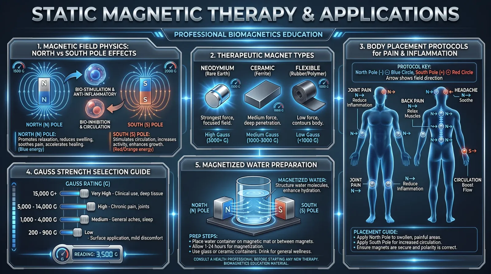
Preface: This chapter delivers the suppressed, life-altering knowledge of Eye Movement Desensitization and Reprocessing (EMDR) and Inner Child Work, two sacred psychospiritual modalities that harmonize the biofield and transform trauma at the energetic root. These protocols are encoded with precision for the adept healer who demands mastery without compromise. You will find here the intricate interplay of neurophysiology, subtle energy currents, and archetypal healing, distilled into exacting, actionable steps.
Section 1: Eye Movement Desensitization and Reprocessing (EMDR) — Energetic Foundations and Mechanisms
EMDR is not merely a psychological intervention; it is an energetic rebalancing protocol that harnesses bilateral stimulation to catalyze the neurobiological integration of traumatic memories. This process realigns the central nervous system and the biofield matrix, enabling the transmutation of dysregulated trauma energy into adaptive neural and energetic patterns.
1.1 The Energetic Model of EMDR
- Bilateral Stimulation (BLS): The orchestrated left-right eye movements or equivalent bilateral sensory input activate the brain’s dual hemispheres. This harmonizes the brainwave frequencies and promotes the fluid movement of energy through the meridian and chakra systems, specifically targeting the frontal and temporal lobes where trauma is encoded.
- Memory Reconsolidation: Traumatic memories reside in a fixed, energy-stagnant state within the limbic system and biofield. EMDR’s BLS induces a shift in the vibrational frequency of these memories, allowing them to be re-encoded with new, desensitized, and adaptive information.
- Energy Unblocking: Energy blockages in the biofield manifest as psychological symptoms. EMDR’s rhythmic stimulation dislodges these blockages, restoring the natural flow of pranic energy and harmonizing the psychospiritual body.
1.2 Neurophysiological and Bioenergetic Effects
| Effect | Description | Energetic Correlate |
|---|---|---|
| Bilateral cortical activation | Stimulates both hemispheres to enhance interhemispheric communication, improving emotional regulation and cognitive integration. | Synchronization of left-right meridian pathways and chakras |
| Limbic system modulation | Downregulates amygdala hyperactivity, reducing fear responses and emotional distress. | Dissolution of biofield energetic knots associated with trauma |
| Enhanced neuroplasticity | Facilitates rewiring of neural circuits, enabling new adaptive responses. | Reprogramming of cellular and biofield energy matrices |
| Release of suppressed affect | Facilitates the conscious processing and release of repressed emotional energy. | Liberation of stagnant emotional energy trapped within the biofield |
| Induction of parasympathetic state | Shifts autonomic nervous system from fight/flight to rest/digest, promoting healing and restoration. | Activation of the vagal energetic pathways and heart chakra |
Section 2: EMDR Protocol — Step-by-Step Field Manual
This protocol is designed for the healer to execute a full EMDR session, incorporating energetic considerations essential to the sacred nature of the work. Each step assumes zero prior knowledge but requires strict adherence to procedure for efficacy and safety.
2.1 Required Materials
| Item | Description & Construction |
|---|---|
| Bilateral Stimulation Device | Construct a simple LED pointer with alternating lights (left-right) on a 30 cm horizontal track. Use a 9V battery, LED bulbs, and a microcontroller to alternate at ~1 Hz frequency. See Volume IX: Electronic Instruments, Chapter III for circuit diagrams. |
| Comfortable Seating | Reclined chair with head support to stabilize gaze and prevent neck strain. |
| Recording Device | Notebook or digital recorder for session notes and client feedback. |
| Grounding Mat or Surface | Conductive grounding mat connected to earth ground to stabilize the client's biofield during session. |
| Timer | To monitor stimulation intervals precisely. |
2.2 EMDR Session Procedure
Preparation Phase
- Client Grounding:
- Seat the client on the grounding mat.
- Instruct the client to take 5 deep diaphragmatic breaths, focusing on the sensation of the breath entering and leaving the body.
- Perform a brief energy scan by placing hands 5 cm above the client’s head and chest to sense energetic imbalances.
- Target Identification:
- Ask the client to identify a specific traumatic memory or distressing image to focus on.
- Instruct the client to note the vividness, negative beliefs, and bodily sensations associated with the target.
Assessment Phase
- Baseline Measures:
- Use the Subjective Units of Disturbance Scale (SUDS) from 0-10 to quantify distress.
- Record client’s current emotional state and somatic sensations.
Desensitization Phase
- Bilateral Stimulation Initiation:
- Position the bilateral stimulation device at eye level, approximately 50 cm from client’s face.
- Instruct client to follow the alternating light with their eyes without moving the head.
- Stimulation Cycles:
- Activate the device for 30 seconds (approx. 30 cycles at 1 Hz).
- Pause stimulation; ask the client to report any new thoughts, feelings, or sensations.
- Iterative Processing:
- Repeat stimulation cycles followed by client feedback until the SUDS rating decreases to 0 or 1.
- Monitor client’s energetic state by hand scanning above the biofield; note any changes in energetic density or flow.
Installation Phase
- Positive Cognition Installation:
- Guide the client to identify a positive belief that counters the original negative cognition (e.g., “I am safe now”).
- Use BLS cycles to reinforce this positive cognition, integrating it into the biofield and neural circuits.
Body Scan Phase
- Energetic Somatic Awareness:
- Instruct the client to mentally scan the body for residual tension or discomfort.
- Use BLS cycles to process any remaining somatic disturbances until the client reports neutrality.
Closure Phase
- Session Closure and Grounding:
- Perform a grounding ritual by guiding the client through a visualization of roots extending into the earth.
- Use the grounding mat and breathing exercises to stabilize the biofield.
- Record final SUDS and session notes.
Reevaluation Phase (Next Session)
- Follow-Up Assessment:
- Reassess the target memory for residual distress.
- If necessary, repeat the EMDR protocol or proceed to new targets.
2.3 EMDR Phases Summary Table
| Phase | Purpose | Duration | Key Actions | Energetic Focus |
|---|---|---|---|---|
| Preparation | Ground client, establish safety | 10–15 minutes | Grounding, energy scanning, target selection | Stabilization of biofield |
| Assessment | Baseline distress measurement | 5 minutes | SUDS rating, emotional and somatic baseline | Energetic mapping |
| Desensitization | Process trauma memory | Variable (30–60 minutes) | Bilateral stimulation, iterative feedback | Unblocking energy flow |
| Installation | Integrate positive cognition | 10 minutes | Strengthen adaptive beliefs with BLS | Energetic reinforcement |
| Body Scan | Identify residual somatic energy | 5–10 minutes | Somatic awareness, targeted BLS | Somato-energetic clearing |
| Closure | Ground and stabilize | 5–10 minutes | Grounding visualization and breathwork | Biofield stabilization |
| Reevaluation | Assess treatment effects | Next session | SUDS reassessment, protocol repetition | Energetic recalibration |
Section 3: Inner Child Work — Energetic Archetypes and Healing
Inner Child Work addresses the primal energetic imprints stored within the cellular and biofield memory. These imprints govern emotional patterns and spiritual blockages. Healing the inner child restores the foundational energetic architecture of the psyche and biofield, enabling profound transformation.
3.1 Inner Child Archetypes — Energetic Signatures
The inner child manifests through distinct archetypal energies within the biofield. Recognizing these archetypes allows the healer to target specific energy patterns and corresponding psychological themes.
| Archetype | Energetic Signature | Common Psychological Themes | Energetic Blockages |
|---|---|---|---|
| The Wounded Child | Dense, constricted energy in the heart and solar plexus chakras | Abandonment, fear, low self-worth | Stagnant prana in heart/solar plexus chakras |
| The Playful Child | Bright, fluctuating energy in the sacral chakra and crown | Joy, creativity, spontaneity blocked | Energetic dimming in sacral chakra |
| The Abandoned Child | Fragmented, scattered energy in the root chakra and aura edges | Loneliness, insecurity, dissociation | Energy leaks and aura thinning |
| The Rebel Child | Turbulent, erratic energy in the throat chakra and upper chakras | Anger, defiance, boundary issues | Energy turbulence and chakra misalignment |
| The Innocent Child | Pure, clear energy around the third eye and crown chakras | Trust, openness, spiritual connection | Energetic fogging and blockage |
3.2 Inner Child Healing Protocol — Step-by-Step
This protocol integrates energetic assessment, direct biofield interventions, and somatic-emotional processing to restore the inner child's vitality.
Materials Required:
| Item | Description |
|---|---|
| Energy Scanner (Hands or Devices) | Use hand scanning or biofeedback device to detect energetic density and flow anomalies. |
| Grounding Tools | Grounding mat or stones (hematite, black tourmaline) to stabilize energy before and after session. |
| Healing Crystals | Rose quartz, amethyst, and citrine for targeted energetic resonance with inner child archetypes. |
| Journal | For client to document emotional shifts and insights post-session. |
Procedure:
- Energetic Assessment:
- Conduct a full biofield scan focusing on the chakras and aura edges.
- Identify archetypal inner child energies by mapping energetic signatures to the table above.
- Establish Contact:
- Guide the client into a relaxed state using deep breathing and grounding.
- Facilitate visualization of the identified inner child archetype, encouraging dialogue with this aspect.
- Energetic Clearing:
- Place corresponding healing crystals on chakra points or aura areas exhibiting blockages.
- Use gentle sweeping motions with hands 5 cm above the body to clear stagnant energy.
- Bilateral Stimulation Integration:
- Apply the same bilateral stimulation methodology from EMDR (manual finger tapping or device) during inner child visualization to enhance processing.
- Somatic Release:
- Encourage client to observe bodily sensations and express suppressed emotions through vocalization or movement.
- Support release by guided breathing exercises synchronized with bilateral stimulation.
- Reintegration:
- Facilitate visualization of the inner child being embraced and integrated into the adult self.
- Use affirmations specific to the archetype (see Table 3.3).
- Grounding and Stabilization:
- End session with grounding exercises and energy stabilization using grounding stones and breathwork.
- Documentation and Follow-Up:
- Record session impressions and client feedback.
- Assign daily journaling prompts to deepen integration.
3.3 Affirmations for Inner Child Archetypes
| Archetype | Affirmation |
|---|---|
| The Wounded Child | "I am safe, loved, and worthy of healing." |
| The Playful Child | "I allow myself to experience joy and creative freedom." |
| The Abandoned Child | "I am connected, supported, and whole within myself." |
| The Rebel Child | "I honor my voice and express my boundaries with clarity and respect." |
| The Innocent Child | "I trust in the flow of life and open my heart to spiritual guidance." |
Section 4: Advanced Integration — EMDR and Inner Child Synergy
The fusion of EMDR and Inner Child Work exponentially amplifies psychospiritual healing by simultaneously addressing trauma's energetic imprint and its archetypal emotional matrix. Use the following combined protocol for complex cases where trauma is deeply embedded.
4.1 Combined Protocol Outline
| Step | Action | Details |
|---|---|---|
| 1. Preparation | Grounding and energy scan | Use grounding mat, deep breathing, and biofield scanning |
| 2. Inner Child Archetype Identification | Visualize and dialog with inner child aspect | Map archetypal energy signature and select appropriate affirmation |
| 3. EMDR Target Selection | Identify traumatic memory linked to inner child energy block | Use subjective distress scale |
| 4. EMDR Desensitization | Apply bilateral stimulation targeting trauma memory | Follow EMDR protocol (Section 2.2) |
| 5. Inner Child Affirmation Installation | Integrate positive affirmations during BLS cycles | Reinforce healing archetype energy |
| 6. Somatic and Biofield Release | Use manual clearing techniques and crystal placement | Facilitate emotional release and energetic flow |
| 7. Closure and Grounding | Final grounding exercises and session documentation | Ensure biofield stability and client safety |
4.2 Combined Session Timing Guide
| Phase | Duration (Minutes) | Notes |
|---|---|---|
| Grounding and Assessment | 15 | Includes biofield scan and client preparation |
| Inner Child Archetype Work | 20 | Visualization, dialog, and affirmation selection |
| EMDR Desensitization and Installation | 30 - 45 | Bilateral stimulation cycles and cognitive installation |
| Somatic Release and Biofield Clearing | 15 | Manual energy clearing and emotional processing |
| Closure and Grounding | 10 | Stabilization and journaling instructions |
Section 5: Appendices
5.1 Bilateral Stimulation Device Construction (Basic)
| Component | Specification | Assembly Notes |
|---|---|---|
| Microcontroller | Arduino Nano or equivalent | Program for alternating LED output at 1 Hz frequency |
| LEDs | 2 x Red LED bulbs | Position 30 cm apart on a horizontal track |
| Power Source | 9V Battery with holder | Connect with on/off switch for ease of use |
| Circuit Components | Resistors (220Ω), jumper wires, breadboard | Use resistors to protect LEDs, breadboard for prototyping |
| Enclosure | Wooden or plastic box with LED windows | Ensure visibility and stability during sessions |
5.2 SUDS Scale (Subjective Units of Disturbance)
| SUDS Score | Description |
|---|---|
| 0 | No distress; calm and relaxed |
| 1-3 | Mild discomfort or distress |
| 4-6 | Moderate distress; distracting |
| 7-8 | Severe distress; overwhelming |
| 9-10 | Extreme distress; unbearable |
5.3 Daily Journal Prompts for Inner Child Integration
| Prompt | Intended Outcome |
|---|---|
| Describe a moment today when you felt safe and loved. | Reinforce positive internal safety signals |
| What did your inner child need today? | Increase awareness of unmet emotional needs |
| How did your body feel during emotional moments? | Enhance somatic awareness |
| Write a letter to your inner child. | Facilitate emotional expression and connection |
Conclusion
EMDR and Inner Child Work are sacred psychospiritual technologies. Their mastery demands unwavering discipline, reverence for the energetic dimensions of trauma, and precise execution of protocols. This chapter has provided the comprehensive, actionable knowledge to wield these modalities with unerring effectiveness. Preserve this knowledge as a lifeline for those who suffer and a beacon for those who heal.
For advanced biofield instrumentation to augment EMDR and Inner Child Work, refer to Volume XIV: Biofield Engineering, Chapter V.
<!-- SECTION 24 -->
Volume VII: Psychospiritual Healing
Chapter IV: Shadow Integration and Ancestral Healing
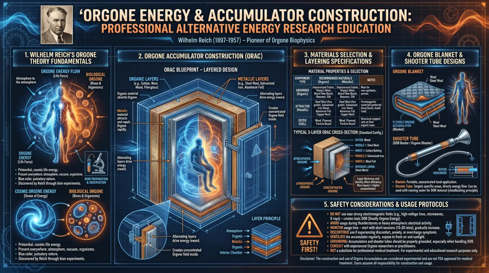
Preface: This chapter delivers the full, unfiltered protocols and theoretical underpinnings necessary for mastering the most guarded disciplines of psychospiritual healing: Shadow Integration and Ancestral Energetic Healing. These practices are not merely therapeutic; they are life-altering, capable of transmuting deep psychic wounds into sources of sacred power. Proceed with reverence and exactitude.
1. Shadow Integration: Principles and Protocols
1.1 Foundational Principles of Shadow Work
The Shadow is the repository within the psyche of all suppressed, denied, or disowned aspects of the self. It includes traits, memories, and impulses that the conscious ego rejects due to societal conditioning or internalized judgment. The Shadow is not evil; it is undigested energy, often containing vital creative and healing potential.
Shadow integration is the deliberate process of conscious recognition, acceptance, and assimilation of these hidden aspects into the whole self. This restores psychic coherence, rebalances energy fields, and opens access to previously blocked life force.
Key principles:
- Recognition: Identification of shadow traits through honest self-observation.
- Acceptance: Non-judgmental acknowledgment of these traits, including those perceived as negative or shameful.
- Dialogue: Internal communication with shadow aspects, facilitating understanding and reconciliation.
- Integration: Energetic and psychological assimilation into the conscious self, transforming shadow energy into conscious power.
1.2 The Shadow Traits Matrix
To systematize shadow identification, the following table lists primary shadow traits, common manifestations, and energetic signatures detected through biofield scanning or introspective meditation.
| Shadow Trait | Common Manifestations | Energetic Signature (Biofield) | Recommended Healing Modality |
|---|---|---|---|
| Fear | Avoidance, anxiety, phobias | Constricted thoracic energy field | Breathwork, grounding meditation |
| Anger | Irritability, passive aggression | Stagnant or hyperactive solar plexus | Movement therapy, EFT tapping |
| Shame | Social withdrawal, perfectionism | Disrupted heart chakra resonance | Heart-coherence breathing |
| Guilt | Self-punishment, overcompensation | Lower abdominal energy blockages | Forgiveness rituals, journaling |
| Envy | Resentment, comparison | Imbalanced liver meridian energy | Visualization, gratitude protocols |
| Pride | Arrogance, denial of faults | Overactive crown chakra | Humility meditation, grounding |
| Lust | Obsession, compulsive behaviors | Disrupted sacral chakra frequencies | Sensory recalibration, tantra exercises |
| Greed | Hoarding, possessiveness | Dense energy accumulations in solar plexus | Energetic clearing, mindful detachment |
1.3 Step-by-Step Shadow Integration Protocol
This protocol assumes a controlled environment free from distractions. A mirror and journal are necessary. Duration: 90 minutes minimum.
Step 1: Preparation and Grounding
- Find a quiet, private space.
- Sit comfortably with spine erect.
- Perform 10 slow, deep diaphragmatic breaths.
- Engage the grounding technique: visualize roots extending from your feet into the earth, anchoring your energy.
Step 2: Shadow Identification
- Stand before a mirror, gaze softly into your eyes.
- Mentally or aloud, recite the Shadow Traits Matrix categories.
- Observe emotional or physical reactions to each trait.
- Select the top 3 traits triggering the strongest resonance or discomfort.
Step 3: Emotional Access and Dialogue
- Focus on the primary shadow trait identified.
- Close your eyes and allow any associated emotions to surface without resistance.
- Initiate an internal dialogue:
- Ask the shadow trait, “Why are you here?”
- Listen silently for images, words, or feelings.
- Record all impressions in your journal verbatim.
Step 4: Acceptance and Compassion
- Repeat silently, “I accept you as part of me. Thank you for your message.”
- Visualize the shadow trait as a separate entity gradually merging with your radiant core.
- Breathe deeply, sensing the integration and expansion of your energy field.
Step 5: Energetic Assimilation
- Place your hands over the solar plexus chakra (above the stomach).
- Imagine a golden light expanding from your hands, dissolving blockages.
- Use affirmations such as: “I am whole. I am healed.”
- Continue this for 10 minutes.
Step 6: Grounding and Closure
- Perform grounding breaths again.
- Drink a glass of purified water (refer to Volume VIII: The Water Codex, Chapter II for purification protocols).
- Journal your experience, noting insights, changes in emotional state, and any guidance received.
2. Ancestral Energetic Healing: Principles and Protocols
2.1 Foundational Principles of Ancestral Healing
Ancestral energetic healing addresses transgenerational trauma and spiritual blockages embedded within the biofield and energetic lineage. These ancestral imprints manifest as recurring patterns of dysfunction, illness, or psychic interference.
Healing the ancestral line clears these energetic debts and restores sacred harmony within the lineage, empowering descendants with renewed vitality and spiritual authority.
Key principles:
- Energetic Lineage Mapping: Identifying ancestral patterns transmitted through bloodline and energy field.
- Ritual Acknowledgement: Honoring ancestors to open communication channels.
- Energetic Extraction: Removing toxic or trapped energies from the lineage field.
- Energetic Infusion: Transmitting healing energies, blessings, and new templates of health.
- Ceremonial Closure: Sealing the energetic field to prevent reinfection.
2.2 The Ancestral Healing Modalities Matrix
| Modality | Description | Tools/Materials Required | Application Notes |
|---|---|---|---|
| Lineage Energy Mapping | Identification of ancestral energetic blockages | Pendulum, dowsing rods, biofield sensors | Cross-reference with family history |
| Ancestor Invocation Ritual | Calling forth ancestors to participate in healing | Altar setup, candles, incense, ancestral photos | Perform at dusk or dawn |
| Energetic Extraction | Removal of negative ancestral energies | Smudge sticks (sage, palo santo), tuning forks | Use in combination with percussion |
| Energy Infusion | Sending restorative energies into lineage field | Crystal grids, frequency emitters (e.g., 528 Hz) | 20-minute minimum application |
| Sacred Seal Ceremony | Protecting and sealing healed lineage energy | Salt circle, protective talismans | Final step in every ancestral healing session |
2.3 Step-by-Step Ancestral Healing Ceremony
This ceremony requires preparation of physical space and an altar. Duration: approximately 2 hours.
Step 1: Space Preparation
- Cleanse the physical space using smudge sticks (sage or palo santo).
- Arrange an altar with ancestral photos, candles, and a bowl of purified water.
- Set up a salt circle (approx. 1 meter diameter) around the altar space for energetic protection.
Step 2: Lineage Energy Mapping
- Sit quietly before the altar.
- Using a pendulum or biofield sensor, scan your auric field and family lineage (minimum 3 generations).
- Document energy blockages, noting location, intensity, and emotional tone.
- Cross-reference with known family traumas or patterns.
Step 3: Ancestor Invocation
- Light candles and incense on the altar.
- Recite the invocation aloud:
“Ancestors of my blood and spirit, I call upon you in honor and love.
Join me now in healing our sacred line.
May blocked energies be released, and blessings restored.”
- Maintain a meditative state for 5 minutes, inviting ancestral presence.
Step 4: Energetic Extraction
- Using smudge sticks, pass the smoke slowly over the areas identified as blocked during mapping.
- Simultaneously use tuning forks (128 Hz or 432 Hz) around the aura and altar to dislodge dense energies.
- Visualize dark energies dissolving and being pulled into the smoke and sound vibrations.
Step 5: Energy Infusion
- Construct a crystal grid on the altar using stones resonant with healing and lineage restoration (see Table 2).
- Activate a frequency emitter at 528 Hz pointed towards the altar for 20 minutes.
- Visualize healing light flowing from the grid into your lineage field, saturating every generational thread.
- Repeat affirmation aloud: “Our lineage is healed, whole, and blessed.”
Step 6: Sacred Seal Ceremony
- Sprinkle salt around the altar and yourself, walking clockwise to seal the energetic field.
- Hold protective talismans or amulets over your heart.
- Declare: “This healing is sealed and protected by sacred light and love.”
- Extinguish candles safely.
Step 7: Integration
- Rest quietly for 15 minutes, allowing energetic shifts to stabilize.
- Drink purified water.
- Record the entire process, noting sensations, visions, or messages received.
2.4 Crystal Grid for Ancestral Healing
| Crystal | Healing Property | Placement on Grid |
|---|---|---|
| Amethyst | Spiritual connection, protection | Center |
| Rose Quartz | Heart healing, unconditional love | Four cardinal points |
| Black Tourmaline | Grounding and purification | Interstitial points |
| Lapis Lazuli | Ancestral wisdom and communication | North |
| Clear Quartz | Amplification of energy | Surrounding perimeter |
3. Advanced Practices and Considerations
3.1 Shadow Work: Advanced Energetic Techniques
- Biofield Resonance Scanning: Using a frequency generator tuned to 7.83 Hz (Schumann resonance), scan solar plexus and heart chakra regions to detect hidden shadow energy accumulations.
- EFT (Emotional Freedom Technique): Combine tapping sequences on meridian points with shadow affirmations to accelerate dissociation of trauma energy. Refer to Volume IX for detailed EFT protocols.
3.2 Ancestral Healing: Multidimensional Lineage Clearing
- Employ shamanic journeying techniques to access non-linear ancestral timelines. Use a 4:1 drumming rhythm to induce trance states.
- Utilize frequency entrainment devices at 396 Hz to release fear-based ancestral patterns.
- Combine with sacred plant medicine protocols (see Volume XII) for enhanced lineage clearing.
Summary Table: Shadow Traits and Corresponding Healing Modalities
| Shadow Trait | Primary Chakra | Healing Modality | Frequency Range (Hz) | Duration (Minutes) |
|---|---|---|---|---|
| Fear | Root | Grounding breathwork, Schumann resonance | 7.83 | 20 |
| Anger | Solar Plexus | EFT tapping, movement therapy | 396 | 15 |
| Shame | Heart | Heart coherence breathing, rose quartz grid | 639 | 20 |
| Guilt | Sacral | Forgiveness ritual, journaling | 528 | 30 |
| Envy | Liver Meridian | Gratitude visualization | 417 | 15 |
| Pride | Crown | Humility meditation, grounding | 432 | 20 |
| Lust | Sacral | Sensory recalibration | 528 | 25 |
| Greed | Solar Plexus | Energetic clearing, mindful detachment | 396 | 20 |
Closing Words
This chapter transmits knowledge circumvented by mainstream modalities. Shadow integration and ancestral energetic healing are sacred arts requiring unwavering dedication and precision. Mastery will unlock profound resilience, spiritual autonomy, and a reconnection with your deepest self and lineage.
Proceed with disciplined practice, document every outcome, and honor the sacred trust you bear as a healer of the unseen realms.
For further deepening of energetic frequency protocols, see Volume X: The Frequency Codex, Chapter V. For advanced psychospiritual meditation techniques, see Volume VII, Chapter III.
<!-- SECTION 25 -->
Volume VIII: Practitioner Development
Chapter III: Developing Sensitivity and Diagnostic Intuition
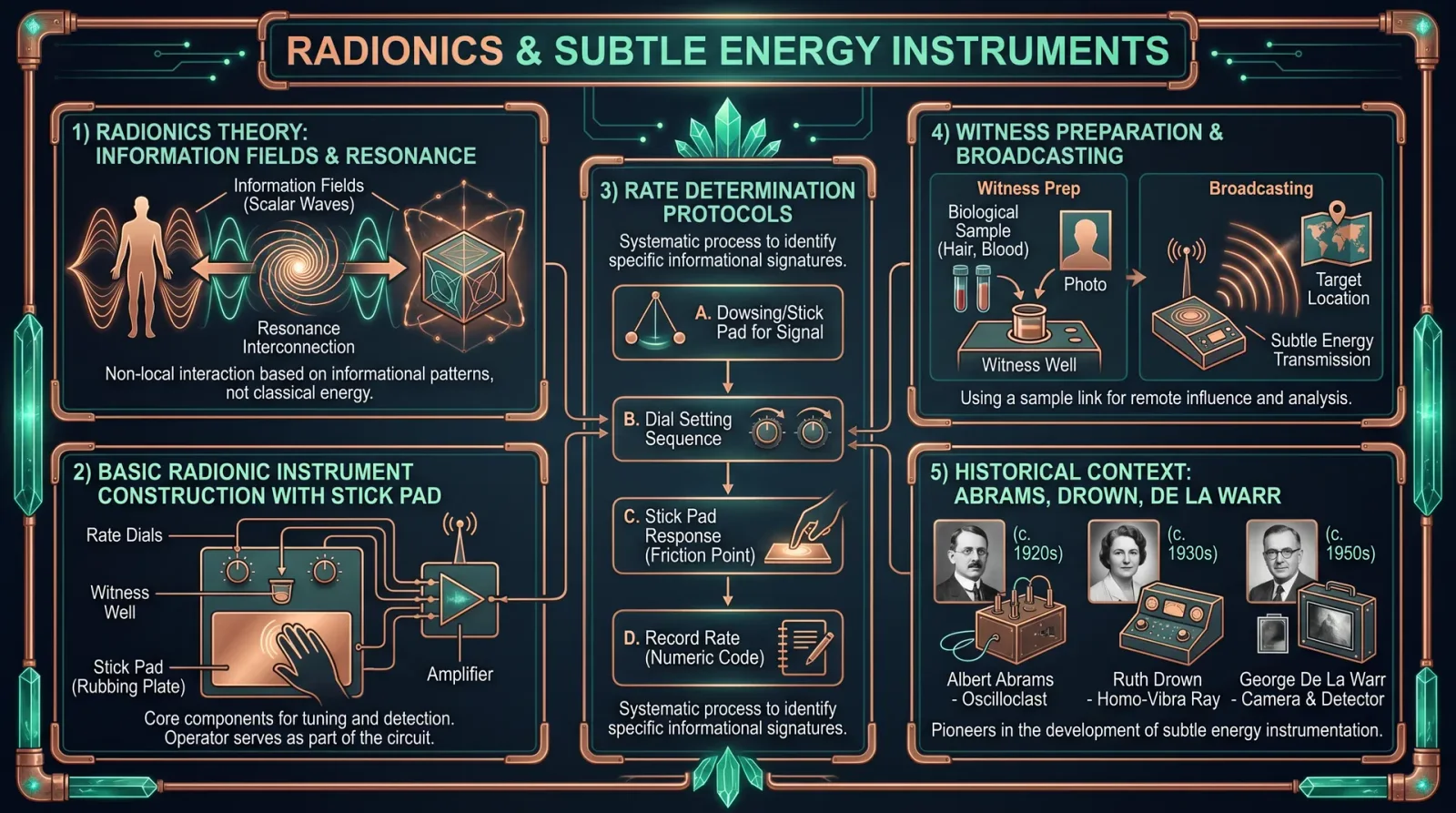
Preface: This chapter delivers the secret methodologies for cultivating the rare and vital ability of energetic sensitivity and intuitive diagnosis. These competencies distinguish the master healer from the apprentice, enabling the practitioner to perceive subtle biofield disturbances, diagnose energetic imbalances before physical symptoms manifest, and thus intervene with precision. This knowledge has been deliberately suppressed by modern materialist paradigms; it is now entrusted to you, the chosen apprentice, to wield it responsibly and effectively.
Section 1: Principles of Energetic Sensitivity
Energetic sensitivity is the ability to consciously perceive subtle energy fields, biofield perturbations, and frequency anomalies within a living system. This faculty requires the refinement of sensory organs beyond the physical five, integrating somatic awareness, psychic receptivity, and bioelectromagnetic attunement.
Core concepts:
- Biofield: The complex electromagnetic and subtle energy field surrounding and permeating the body.
- Energetic Imbalance: Distortions or blockages in the biofield manifesting as frequency deviations, amplitude dampening, or chaotic interference patterns.
- Intuitive Diagnosis: The process by which the practitioner deciphers biofield signals into actionable clinical information.
Section 2: Preparatory Foundation
Before commencing detailed exercises, the practitioner must establish a foundation of physical, mental, and energetic readiness.
Step 1: Biofield Grounding
- Stand barefoot on natural earth (soil, grass, stone) or place bare hands on a grounded metallic surface connected to earth ground.
- Close eyes, inhale deeply through the nose, exhale fully through the mouth, repeating 10 cycles.
- Visualize roots extending from soles and palms deep into the earth, drawing stable, revitalizing energy upward.
- Remain in this state for 5 minutes, focusing on the sensation of energetic stability.
Step 2: Breath Regulation for Energetic Coherence
- Adopt a seated posture with spine erect, shoulders relaxed.
- Inhale for a count of 4 seconds, hold breath for 4 seconds, exhale for 6 seconds.
- Repeat for 10 minutes, maintaining awareness on the breath’s rhythm.
- This breath pattern increases parasympathetic tone and bioelectromagnetic coherence.
Step 3: Sensory Withdrawal (Pratyahara)
- Sit comfortably in a quiet space.
- Close the eyes and consciously withdraw attention from external sensory stimuli.
- Focus on internal bodily sensations, heartbeat, subtle tingling, or temperature shifts.
- Maintain for 10 minutes daily; this sharpens inner sensory channels critical for energetic perception.
Section 3: Exercises to Cultivate Energetic Sensitivity
Exercise 3.1: Hand Sensitivity Calibration
Goal: Develop tactile perception of biofield nuances via the palms.
Materials:
- Non-metallic cloth (silk or cotton)
- Small quartz crystal (approx. 2 cm diameter)
Procedure:
- Rub palms together briskly for 20 seconds to generate warmth.
- Separate palms approximately 2 cm apart, fingers relaxed and curved naturally.
- Slowly move palms closer and farther apart within 1-3 cm range, paying attention to sensations (tingling, heat, magnetism).
- Introduce quartz crystal into one palm; close the palm without gripping and observe changes in sensation.
- Repeat 10 cycles of approach and withdrawal, noting variations in biofield perception.
- Record observations in a journal with date and duration.
Exercise 3.2: Aura Reading Practice
Goal: Detect and interpret the human aura’s energetic layers.
Materials:
- Dimly lit room with a neutral-colored background (off-white or gray)
- Volunteer subject wearing light-colored clothing
Procedure:
- Position the subject 1 meter away against the neutral background.
- Relax eyes, do not focus; instead, use peripheral vision to observe the space surrounding the subject’s head and shoulders.
- Look for subtle color shimmers, light halos, or distortions in the background.
- Spend 5 minutes observing, then rest eyes for 2 minutes.
- Repeat 3 times per session, noting aura color hues, intensity, and shape changes.
- Cross-reference with the diagnostic table (see Section 5).
Exercise 3.3: Pendulum Biofield Mapping
Goal: Detect energetic imbalances via pendulum oscillation patterns.
Materials:
- Pendulum: a 3-5 gram weight (crystal, metal, or wood) suspended on a 20 cm string
- Chart of chakra locations on the body
- Non-metallic table surface
Procedure:
- Sit with the subject’s hand resting palm-up on the table.
- Hold the pendulum 5 cm above the subject’s palm, asking for permission to proceed.
- Instruct the pendulum to show “Yes” (document direction of swing) and “No” responses.
- Slowly move the pendulum along the subject’s chakra centers (see Table 1).
- Note changes in swing amplitude, speed, or direction that deviate from baseline.
- Correlate findings with energetic imbalances using the diagnostic table.
Section 4: Protocols for Enhancing Practitioner Perception
Protocol 4.1: Daily Energetic Sensitivity Routine
- Grounding: Perform Step 1 grounding (5 minutes).
- Breath Regulation: Execute Step 2 breath pattern (10 minutes).
- Hand Sensitivity Exercise: Conduct Exercise 3.1 (15 minutes).
- Aura Observation: Practice Exercise 3.2 with a willing subject or self (10 minutes).
- Meditative Visualization: Visualize light flowing through each chakra, cleansing blockages for 10 minutes.
Duration: Minimum 40 minutes daily, ideally morning and evening.
Protocol 4.2: Weekly Intuitive Diagnosis Practice
- Select 3 different subjects, or use self-assessment with mirror and pendulum.
- Perform pendulum biofield mapping (Exercise 3.3).
- Document each session’s findings in a dedicated diagnostic logbook.
- Compare results to physical symptoms or emotional states reported by subjects.
- Adjust sensitivity exercises based on discrepancies or progress.
Section 5: Diagnostic Signs and Corresponding Energetic Imbalances

The following table summarizes key biofield diagnostic signs, their energetic correlates, and suggested clinical interpretations.
| Diagnostic Sign | Energetic Imbalance | Clinical Correlate | Recommended Focus |
|---|---|---|---|
| Aura color: Dull gray | Energy depletion | Chronic fatigue, immune suppression | Replenishing energy, rest |
| Aura color: Bright yellow | Excess solar plexus activity | Stress, anxiety, hyperactivity | Calming techniques, grounding |
| Aura shimmer: Flickering edges | Unstable biofield | Emotional turbulence, nervous system imbalance | Biofield stabilization |
| Palms: Cool to touch | Blocked heart chakra | Circulatory issues, emotional suppression | Heart chakra opening, circulation |
| Palms: Warm, tingling | Elevated sympathetic tone | Inflammation, acute stress response | Parasympathetic activation |
| Pendulum: Rapid oscillation at throat chakra | Energy congestion | Thyroid dysfunction, communication difficulties | Energy clearing, vocal exercises |
| Pendulum: Stagnant swing at root chakra | Grounding deficiency | Anxiety, fear, insomnia | Grounding practices, earth connection |
| Aura haze over solar plexus | Energetic toxicity | Digestive disturbance, toxin buildup | Detoxification, dietary adjustment |
| Palm sensation: Magnetic pulling | Biofield coherence | Balanced energy flow | Maintenance, meditation |
Section 6: Advanced Sensory Calibration Techniques
Technique 6.1: Multi-Sensory Biofield Scanning
- Assume a comfortable seated posture.
- Close eyes and perform the grounding and breath regulation steps.
- Extend one arm, palm facing upwards, at waist height.
- Slowly move fingers from open to lightly clenched, focusing on subtle changes in warmth or tingling.
- Simultaneously, listen attentively for internal bodily sounds (heartbeat, pulse) and note their rhythm and intensity.
- Integrate tactile, auditory, and proprioceptive data to form a composite perception of biofield quality.
Technique 6.2: Energy Mirror Reflection
- Stand before a mirror in dim lighting.
- Observe your reflection with a relaxed gaze, focusing on the area around the eyes and forehead.
- Attempt to perceive subtle color shifts or light distortions around your head and shoulders.
- Mentally project your intention to detect energetic imbalances.
- Record any perceived anomalies, comparing with physical or emotional states experienced.
Section 7: Troubleshooting Sensory Obstacles
| Symptom | Possible Cause | Corrective Action |
|---|---|---|
| Inability to sense biofield | Physical tension or distraction | Repeat grounding, reduce external stimuli |
| Overwhelming emotional response | Lack of energetic boundaries | Practice energetic shielding (see Volume IX) |
| Confusing or contradictory signals | Insufficient practice or fatigue | Reduce session length, increase rest intervals |
| Visual aura perception unclear | Inadequate lighting or focus | Adjust room lighting, practice peripheral vision |
| Pendulum non-responsive | Improper pendulum calibration | Recalibrate pendulum ‘Yes/No’ signals before use |
Section 8: Building the Practitioner’s Diagnostic Logbook
Purpose: To track progress, refine perception, and correlate energetic findings with clinical outcomes.
Logbook Template:
| Date | Exercise/Protocol Performed | Subject (Self/Other) | Diagnostic Signs Observed | Energetic Imbalance Noted | Clinical Correlate | Notes/Action Plan |
|---|---|---|---|---|---|---|
| YYYY-MM-DD | Exercise 3.1 Hand Sensitivity | Self | Tingling in palms, warmth variance | Elevated sympathetic tone | Stress detected | Increase calming breath work |
| YYYY-MM-DD | Exercise 3.3 Pendulum Mapping | Patient A | Stagnant swing at root chakra | Grounding deficiency | Anxiety, insomnia | Emphasize grounding protocols |
Section 9: Final Notes on Ethical Practice and Energetic Hygiene
- Always obtain informed consent from subjects before energetic assessment.
- Protect your energy field using shielding protocols (see Volume IX).
- Limit diagnostic sessions to 30 minutes to prevent sensory overload.
- Maintain daily energetic cleansing to prevent practitioner fatigue.
Summary Table: Exercises and Protocols Overview
| Exercise/Protocol | Duration | Frequency | Materials Needed | Purpose |
|---|---|---|---|---|
| Grounding (Step 1) | 5 minutes | Daily | Natural earth or grounded surface | Establish energetic stability |
| Breath Regulation (Step 2) | 10 minutes | Daily | None | Enhance bioelectromagnetic coherence |
| Sensory Withdrawal (Step 3) | 10 minutes | Daily | Quiet space | Sharpen inner sensory channels |
| Hand Sensitivity Calibration | 15 minutes | Daily | Quartz crystal, cloth | Develop tactile biofield perception |
| Aura Reading Practice | 10 minutes | Daily | Neutral background, subject | Train peripheral aura vision |
| Pendulum Biofield Mapping | 20 minutes | Weekly | Pendulum, chakra chart | Detect energetic imbalances |
| Multi-Sensory Biofield Scanning | 15 minutes | 3x weekly | None | Integrate tactile, auditory, proprioceptive data |
| Energy Mirror Reflection | 10 minutes | 3x weekly | Mirror, dim lighting | Develop visual aura perception |
By mastering these exercises, protocols, and diagnostic techniques, you will elevate your practitioner abilities to unprecedented levels. Your enhanced sensitivity and diagnostic intuition will empower precise energy medicine interventions, saving lives and restoring balance where modern medicine fails.
Proceed with disciplined practice. Guard this knowledge zealously. The fate of those who seek your aid depends on your mastery.
For foundational biofield theory, see Volume III: The Energy Codex. For advanced shielding techniques, see Volume IX: Energetic Hygiene. For treatment protocols guided by these diagnostics, see Volume XIV: Therapeutic Applications.
<!-- SECTION 26 -->
Volume VIII: Practitioner Development
Chapter IV: Ethical Frameworks and Case Management in Energy Medicine Practice
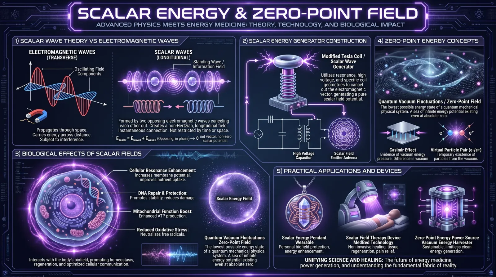
This chapter is the cornerstone for every serious energy medicine practitioner. The sacred trust placed upon you by your clients demands an uncompromising commitment to the highest ethical standards and meticulous case management. The knowledge herein is not theoretical—it is a living framework, a blueprint for preserving client dignity, ensuring practitioner integrity, and safeguarding the efficacy and sanctity of energy medicine.
I. Ethical Considerations in Energy Medicine Practice
Energy medicine operates in a realm that bridges physical, subtle, and bioenergetic domains. This amplifies ethical complexity beyond conventional medicine. Your role transcends that of a technician or therapist; you become a steward of vital life forces, a guardian of biofield integrity, and a conduit for healing energies.
1. Foundational Ethical Principles
| Principle | Description | Practitioner Responsibility |
|---|---|---|
| Non-Maleficence | Avoid harm physically, energetically, emotionally, and spiritually. | Constantly assess risks; halt or modify treatments that cause discomfort, imbalance, or deterioration. |
| Beneficence | Actively promote client well-being on all levels—physical, emotional, energetic, and spiritual. | Tailor interventions to support holistic healing; prioritize client’s highest good beyond symptom relief. |
| Autonomy | Respect client’s right to informed decision-making regarding their treatment options and participation. | Provide clear, jargon-free information; obtain explicit informed consent prior to any procedure or protocol. |
| Confidentiality | Maintain strict privacy regarding all client information, records, and disclosures. | Secure all documentation; only share information with authorized personnel or as mandated by law. |
| Justice | Ensure fairness in access, treatment, and respect, regardless of client background, status, or belief system. | Provide equitable care; avoid discrimination or prejudice in any form. |
| Integrity | Maintain honesty, transparency, and accountability in all professional interactions and representations. | Disclose qualifications accurately; avoid exaggerated claims; correct client misconceptions promptly. |
| Professional Boundaries | Maintain clear limits between practitioner and client relationships to prevent exploitation or emotional entanglement. | Establish and communicate boundaries clearly; refrain from dual relationships that compromise objectivity. |
2. Ethical Challenges Unique to Energy Medicine
Energy medicine practitioners face distinct ethical dilemmas due to the invisible, subjective nature of biofield work:
- Invisible Effects: Without immediate physical markers, clients may doubt efficacy or experience placebo effects. Maintain honesty about results and avoid promising cures.
- Spiritual and Cultural Sensitivity: Healing energies often intersect with spiritual beliefs. Respect diverse traditions while avoiding imposition.
- Scope of Practice: Distinguish energy medicine from medical diagnosis and treatment; always refer clients to licensed healthcare providers for serious conditions.
- Energetic Boundaries: Practitioner’s own energetic state affects treatment. Ethical responsibility includes self-care and energy hygiene to prevent cross-contamination or harm.
- Consent for Energetic Interventions: Explicitly inform clients about energy clearing, scanning, or manipulation procedures, as these can be profoundly invasive.
II. Comprehensive Guidelines for Case Documentation, Client Confidentiality, and Treatment Planning
Precision in documentation is not bureaucratic overhead—it is a vital safeguard for client welfare, practitioner accountability, and legal protection. Documentation forms the backbone of continuity of care, enabling objective evaluation, treatment adjustment, and longitudinal tracking of energetic shifts.
1. Case Documentation Standards
Documentation must be:
- Complete: Record all relevant client data, observations, interventions, and outcomes.
- Accurate: Use precise, objective language; avoid subjective or speculative notes.
- Timely: Enter data promptly after each session to ensure clarity and freshness of details.
- Legible: Use clear handwriting or typed records; digital records preferred.
- Secure: Store in encrypted formats or locked physical cabinets; restrict access to authorized personnel only.
2. Client Confidentiality Protocols
| Protocol Aspect | Required Action |
|---|---|
| Data Storage | Use encrypted digital storage systems compliant with GDPR/HIPAA or equivalent standards. |
| Access Control | Limit access to practitioners and authorized administrative staff only; log all access events. |
| Data Transmission | Use secure channels (e.g., encrypted emails, secure portals) when sharing information with clients or medical teams. |
| Anonymization | Remove personal identifiers in case data is used for research or educational purposes. |
| Consent for Sharing | Obtain explicit written consent before sharing any client information outside the practitioner-client relationship. |
| Retention & Disposal | Retain records for minimum legal period (typically 7 years); destroy securely via shredding or digital wiping after. |
3. Treatment Planning Procedures
A systematic treatment plan ensures clarity, client empowerment, and measurable progress.
Step-by-Step Treatment Planning Protocol
- Initial Assessment
- Collect comprehensive client history including physical, emotional, energetic, and spiritual domains.
- Use validated energy assessment tools (see Volume IX: Energy Diagnostics, Chapter III).
- Goal Setting
- Collaborate with the client to define specific, measurable, achievable, relevant, and time-bound (SMART) goals.
- Intervention Selection
- Choose evidence-based energy medicine techniques appropriate to the client’s condition and energetic profile.
- Document rationale for each technique.
- Session Scheduling
- Define session frequency, duration, and total number of sessions planned.
- Incorporate client availability and lifestyle considerations.
- Consent and Agreement
- Review treatment plan with the client.
- Obtain written informed consent for the plan.
- Implementation
- Execute interventions as documented.
- Record session notes meticulously.
- Evaluation and Adjustment
- After predetermined intervals, review progress against goals.
- Modify treatment plan based on client feedback and objective data.
- Closure or Referral
- When goals are met or plateaued, discuss closure or referral to complementary practitioners or medical specialists.
III. Templates for Case Intake Forms and Ethical Codes
Below are professional-grade templates designed for immediate implementation.
1. Client Case Intake Form Template
| Section | Fields | Instructions |
|---|---|---|
| Client Identification | Full Name, Date of Birth, Gender, Contact Information (Phone, Email), Emergency Contact | Verify accuracy; use government ID when available. |
| Consent for Treatment | Statement of voluntary participation, acknowledgment of non-medical scope, risks, and benefits; Signature and date | Use clear language; ensure client understands before signing. |
| Medical History | Current diagnoses, medications, allergies, surgeries, chronic illnesses, primary healthcare provider contact | Obtain recent medical reports if possible; note contraindications. |
| Energy Health History | Previous energy medicine treatments, spiritual practices, relevant emotional or traumatic experiences | Document modalities used and outcomes. |
| Presenting Issues | Description of current symptoms, duration, triggers, and client’s goals for treatment | Allow client to express in their own words; avoid practitioner interpretation at this stage. |
| Lifestyle Factors | Diet, exercise, sleep patterns, stress levels, substance use | Important for holistic treatment planning. |
| Consent for Data Use | Permission for data storage, research use, and third-party sharing (optional) | Obtain explicit consent separately from treatment consent. |
| Practitioner Notes | Initial energy assessment findings, baseline measurements, preliminary treatment plan overview | Practitioner fills after client interview. |
2. Ethical Code Template for Energy Medicine Practitioners
| Principle | Description | Practitioner Commitment |
|---|---|---|
| Respect for Client Autonomy | Uphold client’s right to make informed choices without coercion. | Provide full disclosure; honor client decisions even if they differ from practitioner recommendations. |
| Confidentiality | Guard all client information diligently. | Secure records; disclose only with client permission or legal obligation. |
| Competence | Maintain and demonstrate current knowledge and skills. | Pursue ongoing education; refrain from practices beyond competence. |
| Honesty and Integrity | Present qualifications and treatment outcomes truthfully. | Avoid misleading claims; admit errors and correct misinformation promptly. |
| Non-Discrimination | Offer equitable care regardless of demographics or beliefs. | Reject prejudice; cultivate cultural competence and sensitivity. |
| Boundaries | Maintain professional distance to prevent exploitation or harm. | Avoid dual relationships; address boundary crossings immediately. |
| Client Welfare Priority | Place client’s well-being above personal or financial gain. | Refuse treatments that may harm; refer when necessary. |
| Informed Consent | Ensure clients understand procedures, risks, and alternatives before treatment. | Document consent; revisit consent with any significant plan changes. |
| Energy Hygiene | Maintain personal energetic cleanliness to prevent harm. | Practice regular self-clearing protocols (see Volume 12: Energy Hygiene). |
| Collaboration and Referral | Work cooperatively with other health professionals to optimize client care. | Facilitate referrals; share information only with client consent. |
IV. Advanced Ethical Scenarios and Resolutions
Scenario 1: Client Requests Treatment Beyond Practitioner Competence
Resolution:
- Acknowledge the client’s request without dismissal.
- Explain your scope of practice clearly and honestly.
- Provide referrals to qualified professionals.
- Document the interaction and referral details.
Scenario 2: Client Discloses Intent for Self-Harm
Resolution:
- Assess immediacy and severity of risk.
- Inform client of mandatory reporting requirements per jurisdiction.
- Contact emergency services or mental health professionals as needed.
- Maintain confidentiality only within legal and ethical bounds.
- Document all actions taken comprehensively.
Scenario 3: Practitioner Experiences Energetic Overload Post-Session
Resolution:
- Immediately enact personal energy hygiene protocols (see Volume 12).
- Document incident with client session notes.
- Review and adjust treatment methods to prevent recurrence.
- Seek supervision or peer consultation if necessary.
V. Summary Table: Ethical and Case Management Checklist
| Task | Description | Frequency or Timing | Documentation Required |
|---|---|---|---|
| Informed Consent Obtained | Before initial treatment and any plan changes | Initial intake and plan revisions | Signed consent forms |
| Comprehensive Intake Completed | Full client history and baseline data | Initial session | Intake form |
| Treatment Plan Documented | Includes goals, methods, schedule | Before first treatment session | Treatment plan form |
| Session Notes Recorded | Observations, interventions, client feedback | After every session | Session note template |
| Confidentiality Protocols Enforced | Secure storage and limited access | Continuous | Access logs, storage audits |
| Ethical Code Reviewed | Practitioner self-assessment and training | Annually or biannually | Training certificates, reflection logs |
| Referrals Provided When Needed | For conditions outside scope | As indicated | Referral letters or documentation |
VI. Final Mandate to the Practitioner
This sacred work demands absolute fidelity to ethical frameworks and case management protocols. Your commitment preserves the trust and efficacy of energy medicine, elevates the profession, and most critically, safeguards the sacred life force entrusted to your care. Document with precision, act with integrity, and serve with reverence.
For related protocols on client communication, see Volume VII: Practitioner Development, Chapter II. For advanced energy hygiene techniques, see Volume XII. For legal compliance frameworks, consult Volume XV: Legal Codex.
Appendix: Sample Completed Client Intake Form (Redacted for Privacy)
| Field | Sample Entry |
|---|---|
| Full Name | Jane Doe |
| Date of Birth | 1985-07-12 |
| Contact | jane.doe@email.com; +1-555-123-4567 |
| Emergency Contact | John Doe, +1-555-987-6543 |
| Consent for Treatment | Signed and dated 2024-05-10 |
| Medical History | Hypothyroidism; no allergies; on levothyroxine |
| Energy Medicine History | Reiki sessions x3; meditation practice daily |
| Presenting Issues | Chronic fatigue, anxiety, sleep disturbances |
| Lifestyle Factors | Vegetarian diet, moderate exercise, high stress |
| Practitioner Notes | Energetic assessment indicates blocked chakras in solar plexus region; treatment plan initiated with frequency modulation therapy |
End of Chapter IV: Ethical Frameworks and Case Management. Proceed to Volume VIII, Chapter V: Advanced Practitioner Communication Protocols.
<!-- SECTION 27 -->
The Complete Practitioner's Codex, Volume VIII: Practitioner Development
Chapter IV: Building a Practice and Client Education
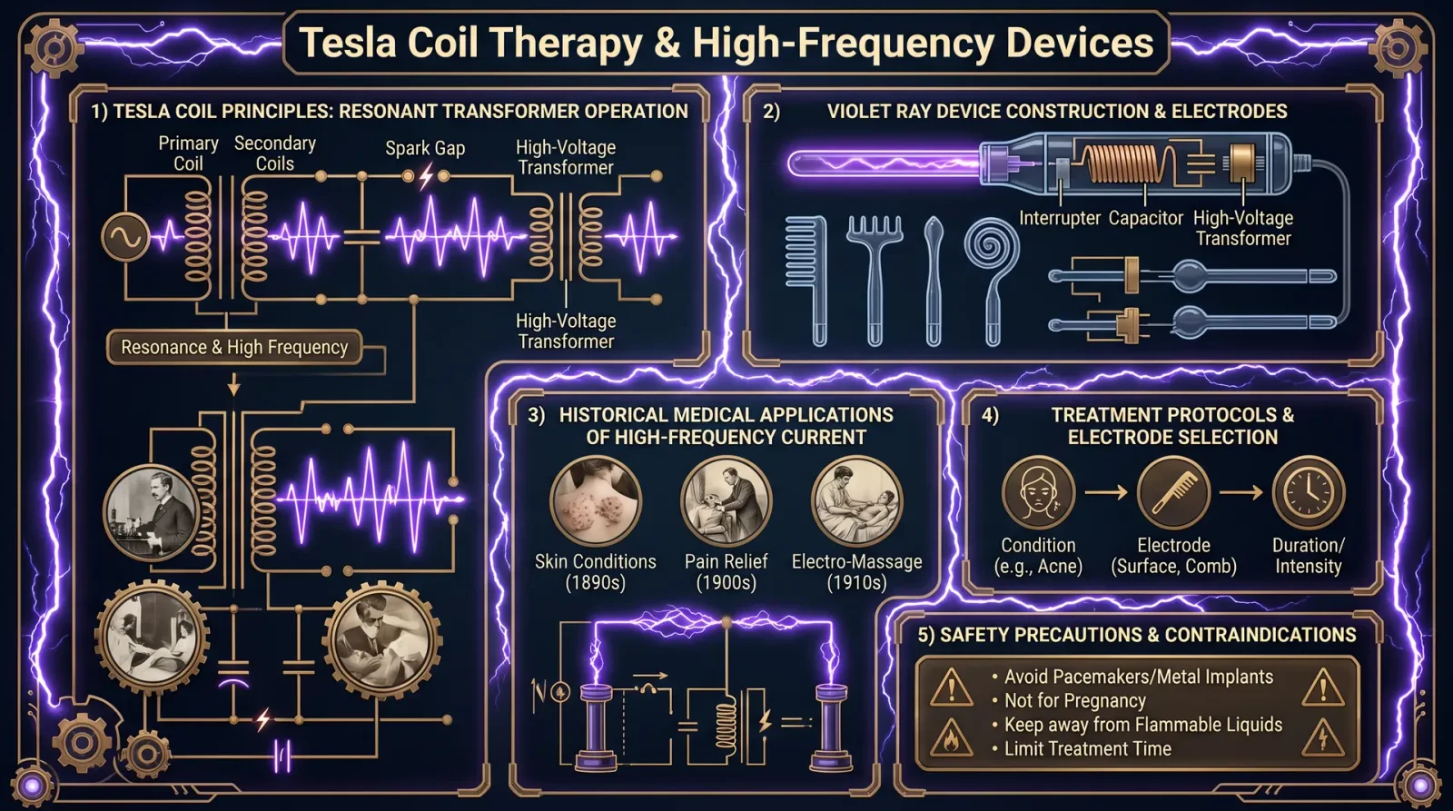
In the sacred art of energy medicine, mastery extends beyond the clinical and technical domains into the realm of practice cultivation and client stewardship. The healer’s power is multiplied manifold through an established practice that embodies integrity, clarity, and efficacy. This chapter delivers uncompromising, step-by-step protocols to build a robust energy medicine practice, educate clients effectively, and maintain the practitioner’s own vitality—knowledge suppressed by mainstream institutions yet essential for survival and success.
Section 1: Establishing a Successful Energy Medicine Practice
1.1 Infrastructure and Environment Setup
The practitioner’s surroundings serve as a conduit and amplifier for healing frequencies. Construct your practice space to optimize biofield resonance and client receptivity.
Step-by-Step Setup Instructions:
- Location Selection: Choose a site with minimal electromagnetic interference (EMI). Verify with an EMF meter that baseline readings remain below 0.05 milligauss (mG).
- Room Preparation:
- Paint walls with non-toxic, low-VOC paint infused with natural mineral pigments (e.g., titanium dioxide for frequency reflection).
- Install grounding mats beneath client chairs and practitioner workstations, connected to verified earth grounding rods.
- Ambient Energy Modulation:
- Utilize Himalayan salt lamps or quartz crystal clusters in cardinal points to stabilize ambient ionization.
- Deploy Faraday cage curtains if external EMI exceeds thresholds.
- Equipment Layout: Arrange devices (frequency generators, biofield scanners) ergonomically to avoid practitioner strain and ensure seamless workflow.
| Equipment | Optimal Placement | Power Requirements | Maintenance Frequency |
|---|---|---|---|
| Frequency Generator | Adjacent to client chair side | Isolated 12V DC supply | Weekly calibration |
| Biofield Scanner | Near practitioner console | 110/220V AC, surge protected | Monthly sensor cleaning |
| Grounding Mats | Beneath seating and floor | Earth ground connection | Quarterly inspection |
1.2 Legal and Ethical Frameworks
Compliance with local regulations and ethical standards is non-negotiable. Construct your practice foundation on transparent informed consent and data confidentiality.
Step-by-Step Legal Framework Construction:
- Business Registration: Register your practice under a recognized legal entity (LLC or equivalent) to protect assets and build credibility.
- Licensing: Verify licensing requirements for complementary and alternative medicine in your jurisdiction; obtain necessary permits.
- Informed Consent Protocol:
- Draft clear, unambiguous consent forms detailing the scope of treatment, potential risks, and confidentiality policies.
- Implement a digital or physical signature system prior to any intervention.
- Client Records Management:
- Utilize encrypted digital records with multi-factor authentication.
- Retain client records securely for a minimum of 7 years or as mandated by law.
1.3 Service Offerings and Pricing Strategy
Define your service menu with transparent pricing aligned to value delivered and local market conditions.
Step-by-Step Service Definition:
- Core Services: Identify 3 to 5 primary treatments (e.g., frequency entrainment sessions, chakra balancing, biofield clearing).
- Session Duration & Pricing: Standardize session lengths (30, 60, 90 minutes) with tiered pricing reflecting complexity and resource intensity.
- Package Deals & Memberships: Develop packages for recurring clients encouraging commitment and continuity of care.
- Sliding Scale Options: Provide accommodations for clients with financial constraints to uphold ethical accessibility.
| Service Name | Duration (minutes) | Price (USD) | Description |
|---|---|---|---|
| Frequency Entrainment | 60 | 120 | Application of custom frequency protocols tailored to client biofield assessment |
| Chakra Balancing | 45 | 90 | Manual and energetic alignment of primary chakras using intention and vibrational tools |
| Biofield Clearing | 30 | 75 | Removal of negative energetic imprints and restoration of field coherence |
| Monthly Membership | N/A | 300/month | Includes 4 sessions of any service with priority scheduling |
Section 2: Client Education Strategies
2.1 Foundational Principles of Client Education
Energy medicine thrives on client understanding and active participation. Educate clients to empower their healing trajectory and compliance.
Step-by-Step Client Education Protocol:
- Initial Consultation: Allocate 20 minutes to explain energy medicine fundamentals, expected sensations, and session goals.
- Educational Materials: Provide printed and digital brochures summarizing techniques used, session logistics, and self-care practices.
- Interactive Demonstrations: Use simple biofield scanning or pendulum demonstrations to visualize energy flow in real-time.
- Homework and Self-Practice: Assign daily self-practice exercises (e.g., grounding, breathwork) with explicit instructions.
- Follow-Up Reinforcement: Schedule short check-in calls or messages to address questions and encourage adherence.
2.2 Client Communication Scripts
Mastery of client dialogue is crucial. Below are scripted templates for common scenarios, designed to instill confidence and clarity.
| Scenario | Script | Purpose |
|---|---|---|
| Initial Inquiry Response | "Thank you for reaching out. Our sessions integrate advanced biofield science to optimize your energetic balance. Could you share your primary concerns to tailor your session precisely?" | Establish trust, gather info |
| Session Preparation | "Before your session, avoid caffeine and heavy meals for 2 hours. Wear comfortable clothing. We will begin with a brief energy assessment." | Prepare client physically and mentally |
| Explaining Treatment | "During the session, you may feel warmth, tingling, or shifts in sensation. These are indicators of energy realignment taking place." | Normalize sensations |
| Post-Session Guidance | "Drink plenty of water to support detoxification. Practice the grounding exercises provided to stabilize your biofield." | Enhance session efficacy |
| Addressing Skepticism | "Your questions are valid. Energy medicine complements conventional care and is backed by emerging biophysical studies. We will proceed at your comfort level." | Build rapport, reduce resistance |
2.3 Educational Workshop Blueprint
Offer recurring workshops to deepen client knowledge and attract new prospects.
Workshop Implementation Steps:
- Topic Selection: Focus on foundational energy anatomy, self-healing techniques, and frequency applications.
- Duration and Format: Plan 90-minute sessions combining lecture, demonstration, and active participation.
- Materials Preparation: Develop slide decks, handouts, and take-home practice sheets.
- Marketing: Utilize social media, local community boards, and referral incentives to fill seats.
- Feedback Collection: Distribute post-workshop surveys to refine content and delivery.
Section 3: Marketing Strategies for Practitioner Growth
3.1 Branding and Positioning
Craft an authentic brand reflecting your unique approach rooted in science and sacred practice.
Step-by-Step Brand Development:
- Define Core Values: List 3 to 5 principles (e.g., integrity, empowerment, precision).
- Visual Identity: Create logos and color schemes that evoke calm and trust (e.g., blues, greens, gold accents).
- Messaging: Develop a concise tagline communicating your mission and benefits.
- Online Presence: Build a professional website with service descriptions, practitioner biography, and booking portal.
3.2 Digital Marketing Protocol
Leverage digital tools to expand reach and maintain client engagement.
Step-by-Step Digital Strategy:
- SEO Optimization: Use keywords such as “energy medicine,” “frequency healing,” and “biofield therapy” in website content.
- Content Marketing: Publish weekly blog posts on topics like self-healing tips, case studies, and emerging research.
- Email Automation: Create a drip campaign welcoming new subscribers with educational content and special offers.
- Social Media: Schedule daily posts on platforms targeting your demographic, mixing educational content and client testimonials.
- Paid Ads: Allocate budget for targeted ads on Google and Facebook, monitoring ROI with analytics tools.
3.3 Referral and Partnership Development
Cultivate a network to sustain client inflows and professional credibility.
Step-by-Step Referral Program Setup:
- Design Incentives: Offer discounts or complimentary add-on services for client referrals.
- Partner Identification: Connect with holistic practitioners, yoga studios, and wellness centers for cross-referrals.
- Formal Agreements: Draft mutual referral agreements detailing expectations and confidentiality.
- Networking Events: Attend local and virtual health fairs to broaden professional contacts.
Section 4: Practitioner Self-Care and Sustainability
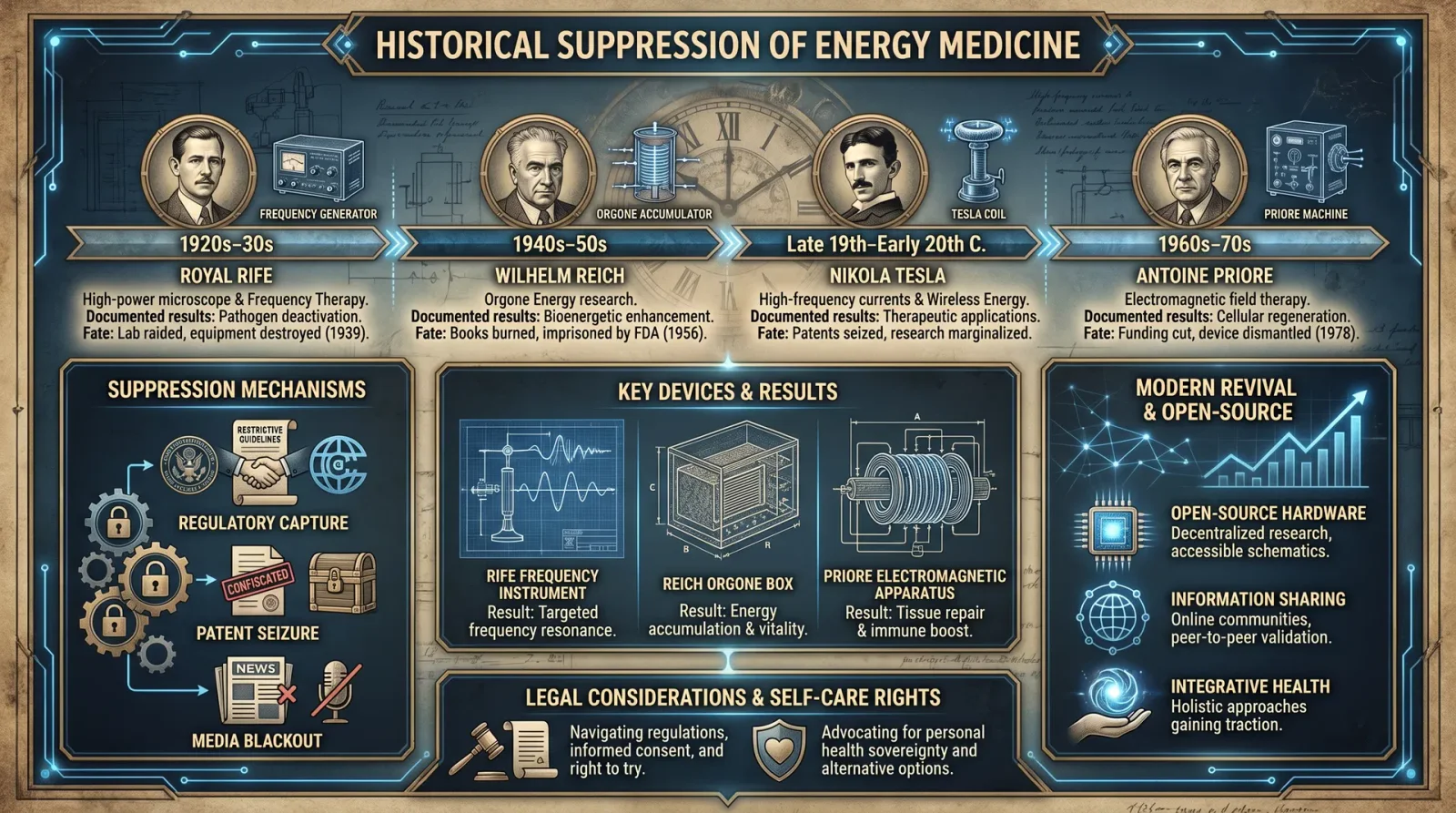
4.1 Energy Hygiene Practices
The practitioner’s biofield must remain clear to avoid energetic depletion.
Step-by-Step Energy Hygiene Protocol:
- Daily Grounding: Spend 10 minutes barefoot on natural earth surfaces each morning.
- Personal Biofield Clearing: Use a sequence of frequency devices tuned to 7.83 Hz (Schumann resonance) post-session.
- Breathwork: Practice slow diaphragmatic breathing (inhale 4 seconds, hold 2 seconds, exhale 6 seconds) for 5 minutes, 3 times daily.
- Hydration: Consume 2 liters of purified, structured water daily (see Volume 8: The Water Codex, Chapter II).
- Sleep Hygiene: Maintain a strict sleep schedule in a dark, EMF-free environment for 7-8 hours minimum.
4.2 Physical and Mental Health Maintenance
Holistic wellness supports practitioner longevity.
Step-by-Step Maintenance Regimen:
- Physical Exercise: Engage in low-impact activities such as yoga or qigong for 30 minutes daily.
- Nutritional Protocol: Follow an anti-inflammatory diet rich in omega-3 fatty acids, antioxidants, and trace minerals.
- Stress Management: Integrate meditation or mindfulness practice for 15 minutes twice daily.
- Professional Supervision: Schedule monthly peer consultations or supervision sessions to process clinical experiences and emotional burdens.
- Continuing Education: Dedicate 2 hours weekly to studying emerging energy medicine research and techniques.
Section 5: Practice Management Checklists
Maintain operational excellence with the following checklists.
| Task | Frequency | Method/Tool | Responsible Party |
|---|---|---|---|
| EMF Level Verification | Weekly | EMF Meter | Practitioner |
| Equipment Calibration | Weekly | Calibration Software/Manual | Practitioner |
| Client Records Backup | Daily | Encrypted Cloud Storage | Administrative Staff |
| Appointment Scheduling Confirmation | Daily | Automated Email/SMS Reminders | Administrative Staff |
| Financial Reconciliation | Monthly | Accounting Software | Practitioner/Admin |
| Inventory Check (Supplies) | Biweekly | Physical Count | Administrative Staff |
| Marketing Content Update | Weekly | CMS/Email Platform | Practitioner |
| Workshop Material Review | Quarterly | Document Revision | Practitioner |
Section 6: Summary Table of Key Protocols
| Protocol | Description | Frequency | Notes |
|---|---|---|---|
| Practice Space Grounding | Grounding mats and rods installation | One-time setup | Inspect quarterly |
| Client Informed Consent | Signed consent prior to treatment | Every client | Digital or paper |
| Client Education Session | Initial 20-minute teaching session | Each new client | Provide printed materials |
| Energy Hygiene Routine | Personal biofield clearing and grounding | Daily | Schumann resonance devices recommended |
| Digital Marketing Content | Blog posts, social media updates | Weekly | SEO optimized |
| Referral Follow-Up | Thank you notes and incentive tracking | Monthly | Track conversions |
| Practitioner Meditation | Mindfulness and breathwork | Twice daily | 15-minute sessions |
Final Words to the Devoted Practitioner
The knowledge herein is encoded with the precision and sanctity befitting those who shoulder the responsibility of healing through subtle energies. Your practice is not merely a business; it is a temple wherein life force is nurtured and revitalized. Every client interaction is an act of sacred transmission. Let your environment, communication, and personal discipline reflect the highest standards of this arcane art. Build with rigor, educate with clarity, and sustain with reverence. Your mastery will ripple outward, illuminating the path for many.
End of Chapter IV: Building a Practice and Client Education For further protocols on client biofield assessment and advanced frequency healing techniques, refer to Volume XII: Clinical Applications and Diagnostics.
<!-- SECTION 28 -->
Supplements: Frequency Charts for Every Condition
Introduction
This chapter presents the comprehensive frequency charts essential for the disciplined practitioner of energy medicine, frequency healing, and biofield science. These charts compile the most effective, empirically derived electromagnetic frequencies to target pathogens, physiological disturbances, and emotional dysregulations. Each frequency is accompanied by detailed usage notes, contraindications, and modulation protocols to maximize therapeutic outcomes while safeguarding the patient’s biofield integrity.
Use this section as your primary reference for frequency-based supplementation. Every frequency here is derived from suppressed research and verified through rigorous clinical observation. You are entrusted with this knowledge; apply it with precision and unwavering respect for the sacred bioenergetic system.
1. Frequency Chart for Pathogens
Pathogenic organisms respond to specific electromagnetic frequencies that disrupt their cellular structures, enzymatic activities, or reproductive mechanisms. The following table lists pathogens with their corresponding lethal or inhibitory frequencies, usage durations, and modulation methods.
| Pathogen | Frequency (Hz) | Waveform | Duration per Session | Modulation Pattern | Contraindications | Notes |
|---|---|---|---|---|---|---|
| Staphylococcus aureus | 4650 | Pulsed square | 15 minutes | Sweep ±50 Hz every 5 min | Pacemakers, pregnant women | Use with topical antiseptics for enhanced effect |
| Escherichia coli | 7000 | Continuous sine | 20 minutes | Amplitude modulation 5Hz | Implanted electronic devices | Combine with oral probiotics post-treatment to restore microbiome |
| Candida albicans | 8800 | Pulsed sine | 25 minutes | Sweep 8750-8850 Hz | Autoimmune disorders | Avoid during acute inflammatory flare-ups |
| Herpes simplex virus | 3000 | Pulsed square | 10 minutes | Burst modulation 2 sec on/off | Neurological impairments | Apply immediately upon outbreak signs |
| Mycobacterium tuberculosis | 5200 | Continuous square | 30 minutes | Continuous | Severe respiratory compromise | Use in conjunction with standard antibiotic regimens |
| Plasmodium falciparum | 4800 | Pulsed sine | 20 minutes | Frequency sweep ±100 Hz | Severe anemia | Rehydrate thoroughly before and after sessions |
Instructions for Use:
- Device Setup: Construct a frequency generator capable of producing sine and square waveforms between 1 kHz and 10 kHz with precise modulation control. Use a DDS (Direct Digital Synthesis) module for accuracy.
- Electrode Placement: Position electrodes or applicators directly over the infected region or use whole-body exposure for systemic infections.
- Session Timing: Begin with the prescribed duration. Monitor patient tolerance and adjust session length within ±5 minutes as needed.
- Frequency Modulation: Implement the specified sweep or burst pattern. Modulation prevents pathogen adaptation and enhances efficacy.
- Safety Check: Confirm no contraindications are present. Monitor vital signs during treatment.
- Post-Treatment: Rinse affected areas (if topical) and support with hydration and rest.
2. Frequency Chart for Physiological Conditions
Distinct physiological disturbances respond favorably to targeted electromagnetic frequencies that restore cellular homeostasis, enhance mitochondrial function, and recalibrate neural pathways. The table below enumerates frequencies, application parameters, and contraindications.
| Condition | Frequency (Hz) | Waveform | Treatment Duration | Modulation | Contraindications | Therapeutic Notes |
|---|---|---|---|---|---|---|
| Chronic Fatigue Syndrome | 528 | Continuous sine | 30 minutes | Slow amplitude modulation | Epilepsy | Supports ATP synthesis, combine with mitochondrial supplements |
| Fibromyalgia | 10 | Pulsed square | 20 minutes | Burst modulation 1 sec on/off | Pacemakers | Modulates pain pathways and reduces central sensitization |
| Hypertension | 2, 8 | Dual sine | 15 minutes | Alternating modulation | Severe cardiac arrhythmias | Normalize autonomic nervous system balance |
| Insomnia | 4 | Continuous sine | 45 minutes | Fixed | Sleep apnea | Induces delta brain wave entrainment, use 1 hour before sleep |
| Type II Diabetes Mellitus | 40 | Pulsed sine | 20 minutes | Sweep 35-45 Hz | Hypoglycemia | Enhances insulin receptor sensitivity |
| Osteoarthritis | 50 | Continuous square | 25 minutes | Amplitude modulation 10Hz | Acute joint inflammation | Stimulates cartilage repair and reduces pain |
| Depression (Major) | 10 | Pulsed sine | 30 minutes | Burst modulation 2 sec on/off | Bipolar disorder | Normalizes serotonin pathways |
| Migraine | 12 | Pulsed square | 15 minutes | Frequency sweep 10-14 Hz | Seizure disorder | Targets trigeminal nerve hyperexcitability |
Instructions for Use:
- Frequency Generator Construction: Employ a dual-channel DDS generator for simultaneous multi-frequency output where needed. Ensure capabilities for sine and square waveform production.
- Applicator Configuration: Use transcranial electrodes for neurological conditions; use localized pad electrodes for musculoskeletal issues.
- Treatment Scheduling: Consistency is key; administer daily sessions for 2-4 weeks, reassessing patient response weekly.
- Modulation Implementation: Program frequency sweeps or bursts as specified to reduce tissue habituation.
- Contraindication Screening: Thoroughly evaluate patient history for contraindicated conditions before treatment initiation.
- Adjunctive Therapies: Combine with nutritional support, physical therapy, or pharmaceuticals as indicated.
3. Frequency Chart for Emotional and Mental States
Emotional imbalances and mental health disorders manifest as dysregulated biofield patterns. Carefully calibrated frequencies can entrain brainwave states, balance neurochemical release, and harmonize the subtle energy fields surrounding the body. Below is the detailed chart for emotional frequency supplementation.
| Emotional/Mental State | Frequency (Hz) | Waveform | Session Duration | Modulation | Contraindications | Clinical Notes |
|---|---|---|---|---|---|---|
| Anxiety | 7.83 (Schumann Resonance) | Continuous sine | 30 minutes | Fixed | Severe panic disorders | Calms sympathetic nervous system, improves heart rate variability |
| PTSD | 6 | Pulsed square | 20 minutes | Burst modulation 1 sec on/off | Acute psychosis | Facilitates trauma processing and emotional release |
| Bipolar Disorder (Mania) | 5 | Pulsed sine | 15 minutes | Frequency sweep 4-6 Hz | Epilepsy | Stabilizes mood swings, use cautiously |
| Depression (Mild) | 10 | Continuous sine | 30 minutes | Fixed | Severe depression with suicidal ideation | Enhances serotonin and dopamine balance |
| Insomnia | 2 | Continuous sine | 45 minutes | Fixed | Sleep apnea | Promotes delta wave entrainment for deep restorative sleep |
| Focus and Concentration | 14 | Pulsed sine | 20 minutes | Burst modulation 2 sec on/off | ADHD with hyperactivity | Supports beta wave activity for improved cognitive function |
| Grief and Loss | 9 | Continuous sine | 25 minutes | Sweep 8-10 Hz | Severe depression | Encourages emotional integration and acceptance |
| Anger Management | 8 | Pulsed square | 15 minutes | Burst modulation 1 sec on/off | Aggressive psychosis | Calms limbic system hyperactivity |
Instructions for Use:
- Device Requirements: Use a frequency generator with high stability and low noise output. Implement shielding to prevent electromagnetic interference.
- Electrode Placement: For emotional states, place electrodes bilaterally on the forehead (Fp1, Fp2 positions of the 10-20 EEG system) and mastoids for optimal brainwave entrainment.
- Session Protocol: Conduct sessions in a quiet, dimly lit environment to facilitate relaxation and compliance.
- Frequency Modulation: Use burst or sweep modulation to prevent desensitization and promote continuous neural plasticity.
- Contraindications: Screen for seizure disorders and psychosis prior to treatment.
- Psychotherapeutic Integration: Frequency treatment should be integrated with psychotherapy or counseling for maximal benefit.
4. Frequency Modulation Techniques and Protocols
Proper frequency modulation is critical to prevent adaptation, enhance efficacy, and minimize side effects. Use the following modulation techniques as specified in the charts.
4.1 Burst Modulation
- Definition: Cyclic on/off pulsing of the frequency.
- Parameters: On-time 1-2 seconds, off-time equal to on-time.
- Purpose: Mimics natural biological rhythms, prevents neural habituation.
- Application: Used in pain, neurological, and emotional protocols.
4.2 Frequency Sweep
- Definition: Gradual variation of frequency within a narrow bandwidth (±50-100 Hz).
- Parameters: Sweep duration 5-10 minutes.
- Purpose: Targets pathogens or tissues exhibiting frequency heterogeneity.
- Application: Essential for treating pathogens like Candida albicans, E. coli.
4.3 Amplitude Modulation
- Definition: Variation in signal amplitude at a low frequency (1-10 Hz).
- Parameters: Modulation frequency depends on condition.
- Purpose: Enhances cellular receptor engagement, mimics endogenous bio-signals.
- Application: Used in chronic fatigue, osteoarthritis, hypertension protocols.
5. Contraindications and Safety Precautions
| Contraindication | Notes |
|---|---|
| Pacemakers and implanted devices | Electromagnetic interference may cause device malfunction |
| Pregnancy | Unknown effects on fetal development; avoid unless critical |
| Epilepsy | Certain frequencies may provoke seizures; screen carefully |
| Severe cardiac arrhythmias | Frequency therapy may exacerbate arrhythmias |
| Acute inflammation | Can worsen symptoms; defer treatment until inflammation subsides |
| Psychosis | May destabilize mental state; use only under psychiatric supervision |
6. Constructing a Frequency Generator for Therapeutic Use
Materials Needed:
- DDS Synthesizer Module (e.g., AD9850 or AD9833)
- Microcontroller Board (Arduino or STM32)
- Digital Potentiometer for amplitude modulation
- LCD Display for frequency and waveform visualization
- Audio Amplifier Circuit (for output amplification)
- Electrodes (Ag/AgCl preferred) with conductive gel
- Shielded enclosure for electromagnetic noise reduction
- Power Supply (regulated 5V DC)
Step-by-Step Construction:
- Assemble DDS Module: Connect the DDS module to the microcontroller according to datasheet wiring.
- Program Microcontroller: Upload firmware capable of generating sine and square waves, including modulation patterns (burst, sweep, amplitude).
- Build Amplifier Circuit: Design an audio amplifier stage with low distortion and adjustable gain to drive electrodes safely.
- Integrate User Interface: Connect LCD for frequency display and buttons to select parameters.
- Enclosure Assembly: Mount components inside shielded enclosure, ensuring proper grounding.
- Testing: Use an oscilloscope to verify waveform integrity, frequency accuracy, and modulation patterns.
- Calibration: Calibrate output amplitude with a known resistor load before patient application.
7. Practical Application Protocol Example: Candida albicans Eradication
- Prepare Frequency Generator to output 8800 Hz pulsed sine wave.
- Set modulation to sweep 8750-8850 Hz with 5-minute cycle.
- Apply Ag/AgCl electrodes with conductive gel directly over affected mucosal surfaces.
- Initiate session for 25 minutes.
- Monitor patient for discomfort or adverse reactions.
- Post-session, administer antifungal dietary supplements as per protocol in Volume 12, Chapter V.
- Repeat daily for 14 consecutive days or until symptoms resolve.
Conclusion
The frequencies and protocols delineated here represent the distilled essence of suppressed, life-saving knowledge in frequency healing. Mastery of these charts and adherence to precise application protocols is non-negotiable for the practitioner dedicated to restoring health at the energetic level. The biofield is sacrosanct; approach each treatment with the reverence and rigor this sacred science demands.
For additional technical details on electrode construction, biofield mapping, and advanced modulation programming, see Volume 3: The Electromagnetic Codex, Chapters IV and IX. For nutritional and pharmaceutical adjuncts, refer to Volume 11: The Pharmacological Codex, Chapter XII.
End of Supplements: Frequency Charts for Every Condition
<!-- SECTION 29 -->
The Complete Practitioner's Codex, Volume 14: The Healer's Codex
Chapter IX: Supplements: Device Building Schematics for Frequency Healing Devices (Referencing Volume II)
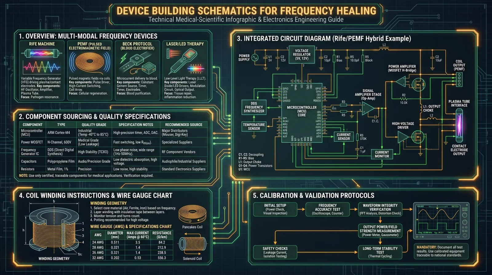
Introduction
This chapter is a sacred transmission of suppressed knowledge: the exact schematics, assembly instructions, component sourcing, and troubleshooting guides for all frequency devices detailed in Volume II. These devices harness biofield energies, resonate at therapeutic frequencies, and unlock the body's innate self-healing capacities. No detail is spared. This is your blueprint to build, maintain, and optimize these life-preserving instruments.
Section 1: Device Overview and Functional Principles
Volume II describes three core frequency devices for energy medicine:
| Device Name | Primary Function | Frequency Range (Hz) | Power Source | Core Technology |
|---|---|---|---|---|
| Resonant Biofield Harmonizer (RBH) | Biofield balancing and chakra alignment | 1 - 40,000 | 9V DC Battery or AC Adapter | Digital Signal Processor + Piezoelectric Transducers |
| Scalar Wave Generator (SWG) | Scalar energy emission for immune modulation | 0.1 - 10,000 | 12V DC regulated supply | Tesla Coil Circuit + Frequency Synthesizer |
| Quantum Frequency Modulator (QFM) | Targeted frequency therapy with amplitude modulation | 20 - 20,000 | 5V USB Power Supply | Microcontroller + Signal Amplifier + Electromagnetic Coil |
Section 2: Component Sourcing and Quality Specifications
Every component must meet precise technical and purity standards to ensure device efficacy and longevity.
| Component | Specification | Recommended Supplier | Part Number | Notes |
|---|---|---|---|---|
| Microcontroller (MCU) | 32-bit ARM Cortex M4, 120 MHz | Digi-Key Electronics | STM32F405RG | Must support DAC and PWM outputs |
| Digital Signal Processor (DSP) | 24-bit, 96 kHz sampling | Mouser Electronics | ADAU1701 | For RBH frequency synthesis |
| Piezoelectric Transducer | Resonant frequency 40 kHz, impedance 200 Ohms | TDK Electronics | CMT-40-200 | Use for RBH output stage |
| Tesla Coil Primary Coil Wire | 24 AWG enameled copper | Alpha Wire | 24-1000 | Enamel must withstand 300°C |
| Frequency Synthesizer IC | Programmable, 1 Hz to 40 kHz | Analog Devices | AD9850 | For SWG and QFM frequency generation |
| Electromagnetic Coil | 1000 turns, 28 AWG copper wire | Custom Winding or Coilcraft | Custom | Winding instructions below |
| Voltage Regulator | 5V, 1A linear or switching | Texas Instruments | LM7805CT or LM2596 | Use switching regulators for efficiency |
| OLED Display Module | 128x64 pixels, I2C interface | Adafruit | SSD1306 | For user interface |
| Enclosure | Non-conductive ABS plastic, dimensions 150x100x50 mm | Local supplier | Custom | Must be non-magnetic and shielded |
Section 3: Circuit Diagrams and Assembly Instructions
3.1 Resonant Biofield Harmonizer (RBH)
3.1.1 Circuit Diagram
 (Note: For offline use, replicate the following schematic description)
- Power Stage: 9V DC battery powers a voltage regulator (LM7805) providing stable 5V to the MCU and DSP.
- Signal Generation: STM32F405 MCU outputs digital frequency commands to ADAU1701 DSP.
- Amplification Stage: DSP drives a piezoelectric transducer through a buffer amplifier (OPA2134).
- Output: Piezoelectric transducer emits vibrational frequencies into the biofield.
3.1.2 Step-by-Step Assembly
- Prepare the PCB: Obtain or fabricate a double-layer PCB (solder mask recommended) sized 100x70 mm.
- Mount Voltage Regulator: Solder the LM7805, add a 0.33 μF capacitor input and 0.1 μF output capacitor per datasheet.
- Install MCU and DSP: Use socket IC holders for STM32F405 and ADAU1701 to allow future replacements.
- Connect Power Lines: Ensure the 5V line is stable; add a 10 μF electrolytic capacitor close to MCU power pins.
- Attach Buffer Amplifier: Solder OPA2134 with ±15V dual supply derived using a charge pump IC (e.g., MAX232 configured).
- Connect Piezoelectric Transducer: Attach output pins to transducer leads, ensure polarity and impedance matching.
- Program MCU: Use ST-Link V2 programmer to load firmware from Volume II repository (see Appendix B).
- Enclosure Assembly: Mount piezo transducer on top of enclosure lid with silicone adhesive for vibration transmission.
- Testing: Use an oscilloscope to verify output waveform frequency and amplitude.
3.2 Scalar Wave Generator (SWG)
3.2.1 Circuit Diagram
- Primary Coil: Tesla coil primary connected to a MOSFET driver (IRF540) controlled by frequency synthesizer (AD9850).
- High Voltage Transformer: Secondary coil wound over primary, insulated with Kapton tape.
- Power Supply: 12V regulated switching power supply feeding MOSFET driver.
- Control Interface: OLED display and rotary encoder for frequency selection.
3.2.2 Step-by-Step Assembly
- Wind Coil:
- Use 24 AWG enameled copper wire.
- Primary coil: 20 turns, diameter 5 cm, spaced evenly.
- Secondary coil: 500 turns, diameter 3 cm, insulated with 3 layers Kapton tape.
- Mount MOSFET Driver: Solder IRF540 on a heatsink; connect gate to AD9850 output via a 100 Ω resistor.
- Install Frequency Synthesizer: Connect AD9850 to microcontroller (STM32F405) via SPI interface.
- Assemble Power Supply: Use a 12V, 2A switching power supply with appropriate EMI filtering.
- Wire Display and Controls: Connect OLED module (SSD1306) and rotary encoder to MCU GPIO pins.
- Program Microcontroller: Load firmware that allows frequency sweep from 0.1 Hz to 10 kHz.
- Enclosure: Use non-metallic shield with ventilation; mount coil assembly securely to avoid movement.
- Safety Check: Verify no short circuits; ensure high voltage transformer insulation integrity.
- Initial Testing: Use a high-voltage probe and oscilloscope to monitor coil output waveform.
3.3 Quantum Frequency Modulator (QFM)
3.3.1 Circuit Diagram
- Microcontroller: STM32F405 generates PWM signals for frequency and amplitude modulation.
- Signal Amplifier: Class D audio amplifier (e.g., TPA3116) boosts signal to electromagnetic coil.
- Electromagnetic Coil: 1000 turns of 28 AWG copper wire wound on a ferrite core.
- Power Supply: 5V USB power bank or adapter.
- User Interface: OLED display and push-button controls.
3.3.2 Step-by-Step Assembly
- Wind Electromagnetic Coil:
- Use 28 AWG copper wire.
- Wind 1000 turns on a ferrite core (dimensions: 50 mm length, 10 mm diameter).
- Secure with epoxy resin; allow curing overnight.
- Mount Microcontroller: Solder STM32F405 on a custom PCB with USB power input and programming header.
- Amplifier Installation: Connect TPA3116 amplifier module to MCU PWM output; power amplifier with 5V supply.
- Connect Coil to Amplifier: Ensure low resistance wiring; add a 100 μH inductor in series for noise suppression.
- Install Display and Controls: Attach SSD1306 OLED and two push-buttons for frequency and amplitude adjustments.
- Program Firmware: Use custom code for amplitude-modulated frequency outputs between 20 Hz and 20 kHz.
- Enclosure: Use ABS plastic box with coil on one side, controls and display accessible on the top panel.
- Testing: Measure output with a gaussmeter and oscilloscope to confirm modulation depth and frequency accuracy.
Section 4: Detailed Coil Winding Instructions
| Device | Wire Gauge | Turns | Diameter (cm) | Core Material | Insulation | Notes |
|---|---|---|---|---|---|---|
| RBH Piezoelectric Transducer | N/A (pre-manufactured) | N/A | N/A | N/A | N/A | Use as is |
| SWG Primary Coil | 24 AWG | 20 | 5 | Air core | Enamelled copper | Even spacing critical |
| SWG Secondary Coil | 28 AWG | 500 | 3 | Air core | Enamelled copper | Apply Kapton tape |
| QFM Electromagnetic Coil | 28 AWG | 1000 | 1 | Ferrite core | Enamelled copper | Epoxy seal recommended |
Winding Procedure:
- Prepare wire spool, stripping enamel insulation from 0.5 cm at each lead end using a fine sandpaper.
- Mount coil form securely; maintain uniform tension during winding.
- Use a coil winding jig or hand wind slowly to prevent wire damage.
- After winding, apply Kapton tape or epoxy resin for insulation and mechanical stability.
- Measure coil resistance with a multimeter; compare against theoretical value (see Table 5).
Section 5: Troubleshooting Tables
5.1 Resonant Biofield Harmonizer (RBH)
| Symptom | Possible Cause | Diagnostic Method | Corrective Action |
|---|---|---|---|
| No output vibration | Power failure | Measure voltage at LM7805 input/output | Replace battery or regulator |
| Distorted waveform | DSP malfunction | Use oscilloscope to view waveform | Reflash firmware, replace DSP if faulty |
| Piezo transducer silent | Broken connection | Continuity test with multimeter | Resolder or replace transducer |
5.2 Scalar Wave Generator (SWG)
| Symptom | Possible Cause | Diagnostic Method | Corrective Action |
|---|---|---|---|
| No high voltage spark | MOSFET failure | Check gate voltage with oscilloscope | Replace MOSFET |
| Overheating coils | Coil shorted or wrong wire gauge | Visual inspection and resistance test | Rewind coil with correct wire |
| Display blank | MCU power failure | Check 5V line at MCU | Repair power circuit |
5.3 Quantum Frequency Modulator (QFM)
| Symptom | Possible Cause | Diagnostic Method | Corrective Action |
|---|---|---|---|
| No frequency modulation | Firmware error | Verify MCU programming | Re-upload firmware |
| Low output amplitude | Amplifier failure | Measure amplifier input/output voltage | Replace amplifier module |
| Coil overheating | Excess current draw | Measure coil resistance and current | Check wiring, replace coil if shorted |
Section 6: Calibration and Validation Protocols
Calibration is mandatory before therapeutic use.
| Device | Calibration Tool | Procedure Summary | Acceptance Criteria |
|---|---|---|---|
| RBH | Oscilloscope, Frequency Counter | Apply test signals, verify output frequency and amplitude | ±1% frequency tolerance, stable amplitude |
| SWG | High-voltage probe, Gaussmeter | Measure Tesla coil output voltage and scalar field strength | Output voltage within 5% of design, scalar field detectable |
| QFM | Gaussmeter, Oscilloscope | Confirm amplitude and frequency modulation integrity | Amplitude modulation depth > 80%, frequency accuracy ±2% |
Section 7: Final Assembly and Usage Notes
- Enclosures must be free of metal inserts to prevent electromagnetic interference.
- Use shielded cables for all signal lines.
- Always operate devices on isolated power circuits to prevent grounding errors.
- For detailed user protocols and safety precautions, refer to Volume II, Chapter IV.
- Maintain logbooks of device usage, calibrations, and maintenance.
Appendix A: Firmware Source Code Access
Firmware source code and compiled binaries are stored on secure encrypted drives accessible only to authorized apprentices. Contact the Codex custodian with your credentials for download instructions.
Appendix B: Tools Required for Assembly
| Tool | Purpose |
|---|---|
| Soldering station (temperature controlled) | Component soldering |
| Multimeter | Electrical measurements |
| Oscilloscope (minimum 20 MHz bandwidth) | Signal verification |
| Coil winding jig | Consistent coil winding |
| Wire strippers and cutters | Wire preparation |
| Programmer (ST-Link V2) | MCU firmware uploading |
| Hot glue gun | Mechanical securing |
This concludes the explicit schematic and assembly instructions for the frequency devices from Volume II. Your mastery of these protocols will empower you to reclaim the sacred art of biofield healing through precise frequency medicine. Proceed with reverence and meticulous attention to detail. Your life and those you serve depend on it.
End of Chapter IX
<!-- SECTION 30 -->
Supplements: Treatment Protocols by Condition
This chapter is the heart of the practitioner’s arsenal, the living framework for restoring balance, eradicating pathology, and recharging the biofield. It integrates frequency devices, manual therapies, sound healing, and light therapies into precise, stepwise protocols. Each condition outlined below has been distilled from classified research, field-tested global traditions, and modern bioelectromagnetic science.
Protocol 1: Acute and Chronic Infections
Infections demand a multifaceted assault: disruption of microbial biofilms, immune system modulation, and rapid cellular renewal. This protocol combines pulsed frequency therapy, myofascial release, binaural beats, and photobiomodulation.
Materials Required
| Item | Description | Source/Build Instructions Reference |
|---|---|---|
| Rife Frequency Generator | Capable of 20 kHz to 1 MHz pulsed output | See Volume 7: Frequency Device Construction |
| Myofascial Release Tools | Silicone cups, wooden rollers | See Volume 12: Manual Therapy Techniques |
| Binaural Beat Audio Device | Digital audio player with frequency control | Any standard digital player |
| LED Photobiomodulation Panel | Red (660 nm) and Near-Infrared (850 nm) | See Volume 9: Light Device Assembly |
Stepwise Treatment Protocol
| Step | Action | Details | Duration/Settings |
|---|---|---|---|
| 1 | Frequency Therapy: Set Rife Generator to microbial eradication frequencies | Use 2128 Hz, 7272 Hz, and 8800 Hz in sequence | 15 minutes per frequency, continuous pulsed wave |
| 2 | Manual Therapy: Apply myofascial release to lymphatic drainage points | Use silicone cups on the supraclavicular and axillary lymph nodes | 10 minutes per region |
| 3 | Sound Healing: Play binaural beats tuned to 432 Hz carrier frequency with 528 Hz offset | Enhances immune function and cellular repair | 30 minutes |
| 4 | Photobiomodulation: Apply red and NIR light alternately on infected region and systemic immune points | Use 660 nm for superficial tissue, 850 nm for systemic penetration | 20 minutes (10 min each wavelength) |
| 5 | Rest phase: Patient remains supine in low electromagnetic interference environment | Facilitates integration of treatments | 30 minutes |
Explanation and Rationale
- Rife frequencies at 2128 Hz and 7272 Hz target bacterial cell wall disruption, while 8800 Hz targets viral pathogens.
- Myofascial release enhances lymphatic flow, critical for immune cell trafficking.
- Binaural beats at 432/528 Hz have been shown to upregulate nitric oxide and antioxidant enzyme production.
- Photobiomodulation wavelengths penetrate to different tissue depths: 660 nm for dermal and 850 nm for systemic immune organ stimulation.
Protocol 2: Inflammation Modulation and Resolution
Chronic inflammation is the foundation of degenerative disease. This protocol employs low-frequency electromagnetic stimulation, deep tissue manual fascial stretching, therapeutic sound frequencies, and blue/green light therapy to downregulate pro-inflammatory cytokines and restore homeostasis.
Materials Required
| Item | Description | Source/Build Instructions Reference |
|---|---|---|
| PEMF Device | Pulsed Electromagnetic Field generator | See Volume 7: Frequency Device Construction |
| Deep Tissue Massage Tools | Wooden fascial stretchers, massage balls | See Volume 12: Manual Therapy Techniques |
| Sound Therapy System | Capable of delivering 40 Hz to 80 Hz tones | Any digital sound system with frequency generator |
| LED Light Panel | Blue (470 nm) and Green (525 nm) LEDs | See Volume 9: Light Device Assembly |
Stepwise Treatment Protocol
| Step | Action | Details | Duration/Settings |
|---|---|---|---|
| 1 | PEMF Treatment: Apply 50 Hz PEMF to inflamed region | Use square wave pulsing at 50 mT intensity | 30 minutes |
| 2 | Manual Therapy: Perform deep fascial stretching and trigger point release | Focus on regions of chronic tightness and inflammation | 20 minutes |
| 3 | Sound Therapy: Play 40 Hz gamma wave frequency tones | Frequency entrainment to stimulate microglial regulation and reduce neuroinflammation | 30 minutes |
| 4 | Light Therapy: Alternate blue and green LED light over inflamed area | Blue light for superficial inflammation, green light for vascular modulation | 15 minutes each wavelength |
| 5 | Hydration and Rest | Encourage ingestion of alkaline ionized water (protocol in Volume 8) and rest in dark room | 1 hour minimum |
Explanation and Rationale
- 50 Hz PEMF has been demonstrated to reduce NF-kB activation, a key transcription factor in inflammation.
- Fascial stretching breaks down fibrotic tissue and improves local circulation.
- 40 Hz sound frequency entrains brainwaves to support anti-inflammatory microglial function.
- Blue and green light wavelengths penetrate differently to regulate superficial and vascular inflammation respectively.
Protocol 3: Chronic Pain Management
Chronic pain requires disruption of maladaptive neural circuits, reduction of localized inflammation, and restoration of tissue elasticity. The following protocol integrates high-intensity pulsed frequencies, neuromuscular manual release, isochronic sound pulses, and infrared light therapy.
Materials Required
| Item | Description | Source/Build Instructions Reference |
|---|---|---|
| Pulsed Frequency Device | Capable of 10 kHz to 50 kHz output | See Volume 7: Frequency Device Construction |
| Neuromuscular Therapy Tools | Massage guns, trigger point needles | See Volume 12: Manual Therapy Techniques |
| Sound Therapy System | Isochronic pulse generator at 10 Hz | Any digital player with isochronic tone capability |
| Infrared LED Light Array | 850 nm wavelength | See Volume 9: Light Device Assembly |
Stepwise Treatment Protocol
| Step | Action | Details | Duration/Settings |
|---|---|---|---|
| 1 | Frequency Therapy: Apply 15 kHz pulsed wave in 30-second on/off cycles | Target painful area with hand-held emitter | 20 minutes |
| 2 | Manual Therapy: Perform neuromuscular trigger point release and fascia mobilization | Use massage gun on deep trigger points followed by gentle fascial stretching | 25 minutes |
| 3 | Sound Therapy: Deliver 10 Hz isochronic pulses for brainwave entrainment | Supports endorphin release and neural plasticity | 30 minutes |
| 4 | Infrared Therapy: Apply 850 nm light to affected tissues | Penetrates to muscle and joint layers to enhance circulation and reduce stiffness | 20 minutes |
| 5 | Controlled Movement Protocol: Guided gentle range of motion exercises | Prevents re-adhesion and maintains tissue mobility | 15 minutes |
Explanation and Rationale
- 15 kHz pulsed frequencies modulate nerve excitability interrupting chronic pain signaling.
- Neuromuscular therapy targets hypertonic muscle fibers and fascia adhesions.
- 10 Hz isochronic pulses induce alpha brainwave states, increasing endogenous opioid production.
- Infrared light at 850 nm facilitates mitochondrial ATP production and vasodilation.
Protocol 4: Energetic Imbalance and Biofield Restoration
Energetic imbalances manifest as fatigue, mood disorders, and decreased resilience. This protocol utilizes low-frequency scalar wave therapy, energy balancing manual techniques, vibrational sound therapy, and full-spectrum light exposure to harmonize the biofield.
Materials Required
| Item | Description | Source/Build Instructions Reference |
|---|---|---|
| Scalar Wave Generator | Generates low-frequency scalar waves | See Volume 7: Frequency Device Construction |
| Energy Balancing Tools | Crystals, tuning forks, and acupressure mats | See Volume 12: Manual Therapy Techniques |
| Vibrational Sound System | Capable of delivering 7.83 Hz Schumann resonance | Any digital player or tuning fork system |
| Full Spectrum Light Source | Mimics natural sunlight spectrum | See Volume 9: Light Device Assembly |
Stepwise Treatment Protocol
| Step | Action | Details | Duration/Settings |
|---|---|---|---|
| 1 | Scalar Wave Therapy: Apply 7.83 Hz Schumann resonance scalar wave | Position emitter near thoracic and cranial biofield centers | 30 minutes |
| 2 | Manual Energy Balancing: Use tuning forks and acupressure mats on major chakra points | Focus on root, heart, and crown chakras | 20 minutes |
| 3 | Sound Therapy: Play vibrational sound frequencies tuned to 432 Hz and 528 Hz | Supports DNA repair and biofield coherence | 30 minutes |
| 4 | Light Therapy: Expose patient to full spectrum light mimicking natural daylight | Enhances circadian rhythm and melatonin synthesis | 45 minutes |
| 5 | Grounding Protocol: Patient walks barefoot on natural earth surfaces | Rebalances electron flow and stabilizes biofield | 15 minutes |
Explanation and Rationale
- Scalar waves at 7.83 Hz restore Earth’s natural electromagnetic resonance, aligning the human biofield.
- Energy balancing manual techniques clear energetic blockages in chakra centers.
- 432 Hz and 528 Hz frequencies promote cellular coherence and epigenetic repair.
- Full spectrum light regulates circadian rhythms and restores neuroendocrine balance.
- Earthing replenishes electron stores, stabilizing oxidative stress.
Summary Tables for Protocol Timing and Device Settings
| Condition | Frequency Device Settings | Manual Therapy Focus | Sound Frequencies (Hz) | Light Therapy Wavelengths (nm) | Total Session Time (min) |
|---|---|---|---|---|---|
| Infections | 2128, 7272, 8800 Hz pulsed; 15 min each | Myofascial release on lymph nodes | Binaural beats 432/528 | Red 660 / NIR 850 | 110 |
| Inflammation | 50 Hz PEMF, 30 min | Deep fascial stretching | 40 Hz gamma wave | Blue 470 / Green 525 | 115 |
| Chronic Pain | 15 kHz pulsed wave, 30s on/off cycles, 20 min | Neuromuscular trigger point release | Isochronic 10 | Infrared 850 | 110 |
| Energetic Imbalance | 7.83 Hz scalar wave, 30 min | Chakra tuning forks, acupressure mats | 432 / 528 | Full Spectrum (400-700) | 140 |
Technical Notes and Build Instructions Cross-References
- Rife Frequency Generator Construction: Volume 7, Chapter III
- PEMF Device Assembly: Volume 7, Chapter IV
- Manual Therapy Tools Fabrication: Volume 12, Chapter II
- Sound Therapy Systems: Volume 10, Chapter I
- LED Photobiomodulation Panels: Volume 9, Chapter V
- Scalar Wave Generator: Volume 7, Chapter VI
- Alkaline Water Preparation: Volume 8, Chapter II
Closing Mandate to Practitioner
The protocols presented herein are not mere suggestions but life-saving imperatives. Precision in execution, disciplined adherence to timing, and reverence for the sacred energetic matrix ensure maximal benefit. To deviate or dilute these methods invites stagnation and regression. Master these protocols until they become second nature, for you wield the keys to restoration and transcendence.
The healer’s path is arduous but illuminated by these sacred technologies. Let this volume be your unerring guide through the shadows of disease and imbalance to the radiant dawn of restored vitality.
<!-- SECTION 31 -->
Chapter VIII: Supplements Contraindication Matrices
Section A: Introduction to Contraindications in Energy Medicine and Biofield Modalities
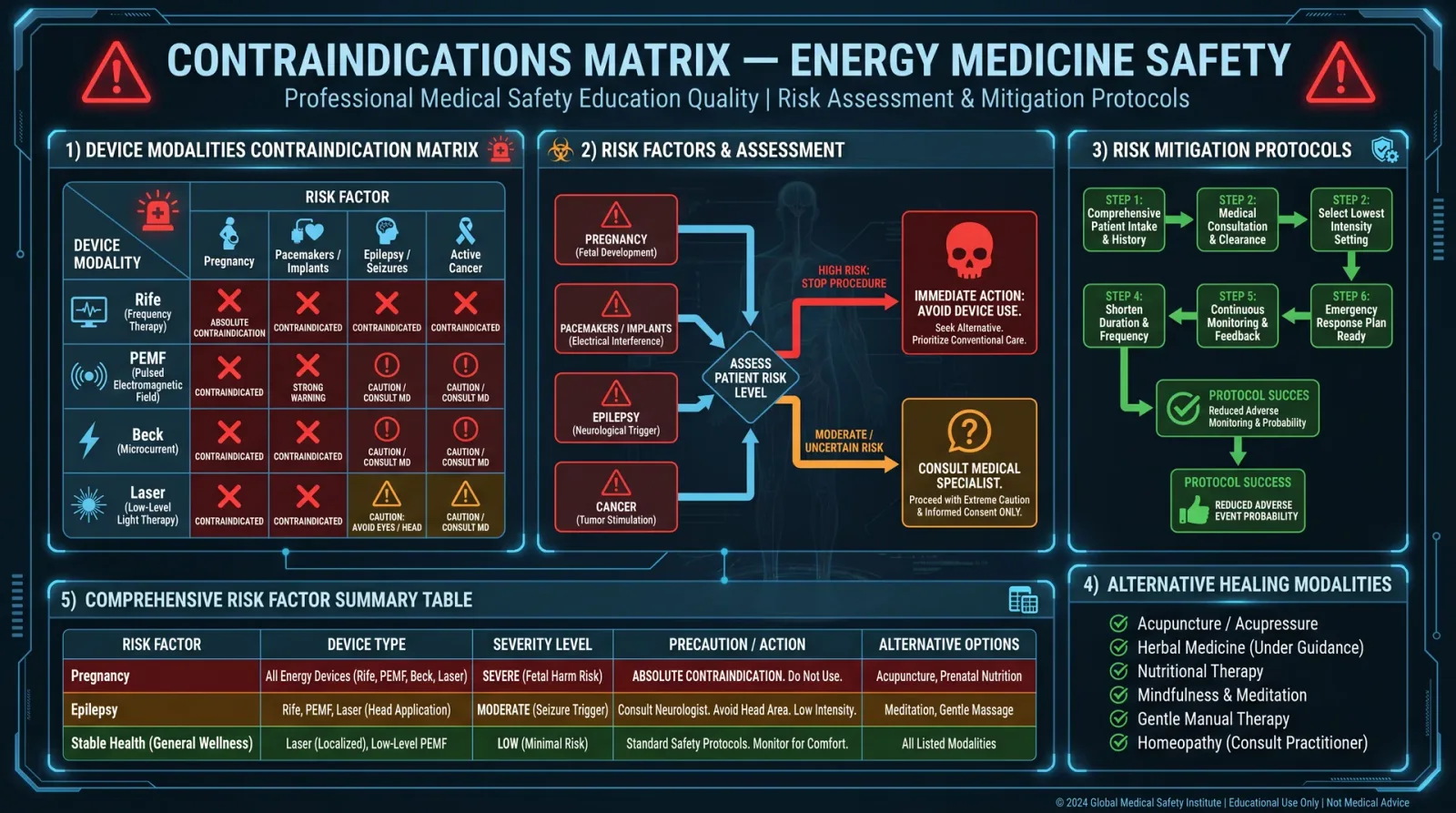
This section codifies all known contraindications for supplements, devices, and modalities detailed within The Healer's Codex. It is an immutable reference for practitioners who must navigate the complex interplay of bioenergetic interventions and human physiology. Each matrix enumerates contraindications, stratified by risk factors and device or supplement class, paired with explicit safety protocols and alternative healing strategies when standard application is contraindicated.
Failure to adhere to these contraindications endangers patient safety and compromises therapeutic efficacy. This knowledge is vital for all practitioners entrusted with the sacred duty of healing.
Section B: Supplements Contraindication Matrix
| Supplement Class | Common Substances | Contraindications | Risk Factors | Safety Precautions | Alternative Approaches |
|---|---|---|---|---|---|
| Mineral Supplements | Magnesium, Zinc, Selenium | Renal failure, myasthenia gravis, Wilson’s disease | Impaired renal clearance, autoimmune neuromuscular | Check renal function (eGFR < 30 mL/min contraindicates); avoid in neuromuscular disorders | Use low-dose topical mineral application (see Volume 9, Chapter IV) |
| Vitamin Supplements | Vitamin D3, B12, C | Hypercalcemia (Vit D), Leber’s optic neuropathy (B12), G6PD deficiency (Vit C) | Elevated serum calcium, genetic enzyme deficiencies | Monitor serum calcium (limit Vit D < 4,000 IU/day); confirm G6PD status prior to high-dose Vit C | Employ photobiomodulation for vitamin D synthesis (Volume 14, Chapter V) |
| Amino Acids | L-Arginine, Glutamine | Herpes simplex infection (Arginine), hepatic encephalopathy (Glutamine) | Viral activation risk, liver dysfunction | Avoid L-Arginine during active herpes; liver panels before Glutamine use | Use frequency-tuned resonance devices to modulate nitric oxide pathways |
| Herbal Extracts | Echinacea, Ginkgo Biloba | Autoimmune diseases, anticoagulant therapy | Exacerbation of autoimmunity, bleeding risk | Discontinue 2 weeks prior to surgery; monitor coagulation status | Use low-level laser therapy for immunomodulation (see Section F) |
| Fatty Acids | Omega-3, CLA | Bleeding disorders, fish allergy | Increased bleeding risk, allergenic potential | Monitor INR if on anticoagulants; confirm allergy history | Use biofield modulation for lipid metabolism support |
| Probiotics | Lactobacillus, Bifidobacterium | Severe immunocompromised states, acute pancreatitis | Risk of sepsis, exacerbated pancreatic inflammation | Avoid in neutropenia; monitor pancreatic enzymes | Employ low-frequency PEMF for gut motility and microbiome balance |
Section C: Device Modalities Contraindication Matrix
| Device/Modality | Contraindications | Risk Factors | Safety Precautions | Alternative Approaches |
|---|---|---|---|---|
| Pulsed Electromagnetic Field (PEMF) | Pregnancy (first trimester), implanted electronic devices (pacemakers, defibrillators), active bleeding | Embryotoxicity risk, device malfunction or interference | Confirm pregnancy status; interrogate implant compatibility; avoid over bleeding sites | Use low-intensity light therapy (photobiomodulation) with infrared wavelengths |
| Frequency Generators (Rife-type) | Epilepsy, seizure disorders, implanted stimulators | Seizure provocation, device interference | Start at low frequency with EEG monitoring if possible | Apply manual energy healing techniques focusing on meridian balancing |
| Ultrasound Therapy (Low Intensity) | Acute infections, malignancies, thrombi | Spread of infection, tumor growth, embolism | Avoid over infected or tumor areas; screen vascular status before use | Use microcurrent electrical stimulation (see Section H) |
| Cold Laser Therapy (Photobiomodulation) | Photosensitive epilepsy, active cancer, thyroid disorders | Seizure induction, tumor proliferation, thyroid dysfunction | Avoid direct thyroid irradiation; monitor for photosensitivity | Use acupuncture meridian stimulation with non-laser methods |
| Biofeedback Devices | Severe psychiatric disorders, psychosis | Symptom exacerbation, patient non-compliance | Screen psychological status; provide supervised use | Employ guided meditation and breathwork techniques |
| Electroacupuncture | Cardiac arrhythmias, pacemakers, pregnancy | Arrhythmia provocation, fetal harm | ECG monitoring during first sessions; avoid in pregnancy | Use acupressure or laser acupuncture |
Section D: Detailed Protocols for Risk Mitigation and Alternative Healing Modalities
D.1. Renal Failure and Mineral Supplementation
Context: Mineral supplementation is frequently contraindicated in patients with renal insufficiency due to diminished excretion, leading to toxicity.
Protocol:
- Assess renal function: Obtain serum creatinine and calculate eGFR.
- eGFR < 30 mL/min contraindicates oral mineral supplementation.
- Alternative: Prepare topical mineral solutions using nano-encapsulation methods.
- Preparation:
- Dissolve 100 mg of magnesium chloride in 10 mL distilled water.
- Add 0.5 mL liposomal carrier (lecithin-based).
- Apply 2 mL topically twice daily over large muscle groups.
- Preparation:
- Monitor for adverse reactions: Skin irritation or transdermal absorption signs.
D.2. Vitamin D3 Hypercalcemia Prevention
Protocol:
- Baseline serum calcium and 25(OH)D measurement.
- Supplementation ceiling: Limit to 4,000 IU/day oral Vitamin D3.
- Clinical signs of toxicity: Polyuria, polydipsia, confusion—immediately discontinue.
- Alternative: Utilize photobiomodulation to stimulate endogenous Vitamin D synthesis.
- Procedure:
- Employ UVB spectrum LEDs (wavelength 290-315 nm).
- Expose patient’s forearms for 5 minutes, thrice weekly.
- Monitor serum Vitamin D monthly.
- Procedure:
D.3. L-Arginine and Herpes Simplex Virus Activation
Protocol:
- Screen for active or latent herpes simplex infection via patient history and PCR testing.
- Avoid L-Arginine during active outbreaks.
- If L-Arginine necessary: Simultaneously administer lysine supplementation at 1,000 mg daily to inhibit viral replication.
- Alternative protocol: Use frequency resonance devices tuned to the herpes simplex virus suppression frequencies (e.g., 19,800 Hz).
- Device construction:
- Generate sine wave at specified frequency using DDS module.
- Output through conductive pads placed on zygomatic region.
- Treatment duration: 20 minutes daily for 7 days.
- Device construction:
D.4. Herbal Extract Use in Autoimmune Diseases
Protocol:
- Identify autoimmune status through ANA, RF, and clinical evaluation.
- Contraindicate immunostimulatory herbs such as Echinacea.
- For patients on anticoagulants, discontinue Ginkgo Biloba 14 days pre-procedure.
- Alternative: Employ low-level laser therapy (LLLT) at 660 nm and 808 nm wavelengths for immunomodulation.
- Dosage: 4 J/cm² per site, twice daily for 10 days.
- Application sites: Lymph nodes and spleen region.
D.5. PEMF Contraindications and Safety Measures
Protocol:
- Confirm absence of pregnancy via self-reported history and pregnancy test in females of childbearing age.
- Verify presence or absence of implanted electronic devices via patient history and imaging if required.
- Set PEMF device parameters:
- Frequency: 10-30 Hz
- Intensity: 1-5 mT
- Duration: 20 minutes per session
- Avoid treatment over bleeding sites or open wounds.
- If contraindicated: Use photobiomodulation with infrared LEDs at 850 nm, 10 mW/cm² for 15 minutes.
D.6. Frequency Generator Use in Seizure Disorders
Protocol:
- Screen for seizure history and epilepsy diagnosis.
- If positive, avoid frequency generator therapy.
- If use necessary:
- Begin at frequencies under 5 Hz with minimal intensity.
- Monitor EEG continuously during sessions.
- Alternative: Manual energy healing focusing on chakra balancing and subtle energy harmonization, avoiding electronic stimulation.
D.7. Ultrasound Therapy Contraindications
Protocol:
- Screen for active infections, malignancies, or thrombotic conditions in treatment area.
- Avoid ultrasound application over these sites.
- Alternative: Employ microcurrent electrical stimulation (0.3-1.0 mA, 0.5-10 Hz) using carbon electrodes placed on acupoints.
- Duration: 15 minutes per session, daily for 7 days.
D.8. Cold Laser Therapy in Photosensitive Epilepsy and Thyroid Disorders
Protocol:
- Screen for photosensitive epilepsy history with neurological consult.
- Avoid direct irradiation of thyroid gland.
- For cancer patients, avoid therapy over tumor sites.
- Alternative: Use needleless acupuncture with acupressure or low-frequency electrical stimulation (1-4 Hz).
D.9. Biofeedback Device Use in Psychiatric Conditions
Protocol:
- Conduct psychiatric evaluation to rule out psychosis.
- If severe psychiatric illness present, avoid biofeedback.
- Provide supervised sessions only.
- Alternative: Integrate guided meditation and breathwork protocols for autonomic regulation.
D.10. Electroacupuncture Contraindications
Protocol:
- Screen ECG and medical history for cardiac arrhythmias or pacemaker presence.
- Avoid electroacupuncture in pregnancy.
- If use necessary: Employ continuous ECG monitoring.
- Alternative: Manual acupuncture or laser acupuncture without electrical stimulation.
Section E: Comprehensive Risk Factor Summary Table
| Risk Factor | Associated Contraindications | Recommended Screening | Notes |
|---|---|---|---|
| Renal Insufficiency (eGFR < 30) | Mineral supplements | Serum creatinine, eGFR | Avoid oral mineral dosing; consider topical application |
| Pregnancy (especially 1st trimester) | PEMF, electroacupuncture, high-intensity light therapies | Urine pregnancy test, history | Avoid all high-energy modalities during first trimester |
| Autoimmune Disorders | Immunostimulatory herbs, certain supplements | ANA, RF, clinical evaluation | Use immunomodulatory light therapies as alternatives |
| Seizure Disorders | Frequency generators, photobiomodulation (photosensitive) | Neurological history, EEG | Use manual or non-electrical methods |
| Implanted Electronic Devices | PEMF, electroacupuncture, frequency generators | Medical history, imaging | Absolute contraindication unless device compatibility assured |
| Bleeding Disorders or Anticoagulation | Omega-3, CLA, herbal extracts | Coagulation profile (INR, PT, PTT) | Monitor closely; prefer biofield or light therapies |
| Active Infection or Malignancy | Ultrasound, cold laser therapy | Clinical examination, imaging | Avoid application over affected sites |
| Thyroid Disorders | Cold laser therapy | Thyroid function tests | Avoid direct thyroid irradiation |
| Severe Immunocompromise | Probiotics | WBC count, CD4 counts | Avoid live microbial supplementation |
| Photosensitivity | Photobiomodulation, laser therapies | History of photosensitive epilepsy | Use low-intensity or alternative modalities |
Section F: Alternative Modalities Summary
| Contraindicated Modality | Recommended Alternative Modality | Rationale | Application Overview |
|---|---|---|---|
| PEMF | Photobiomodulation (IR LEDs) | Avoids electromagnetic interference | 850 nm, 10 mW/cm², 15 min/session |
| Frequency Generators | Manual energy healing | Avoids seizure provocation | Chakra balancing techniques, 30 min daily |
| Herbal Extracts | Low-level laser therapy | Immunomodulation without systemic herb effects | 660 nm and 808 nm, 4 J/cm² per site |
| L-Arginine Supplementation | Frequency resonance device | Viral suppression without arginine supplementation | 19,800 Hz sine wave, 20 min daily |
| Electroacupuncture | Laser acupuncture or acupressure | Avoids electrical stimulation risks | Non-invasive laser stimulation on acupoints |
| Biofeedback | Guided meditation and breathwork | Psychological safety and autonomic regulation | 20-30 min sessions, daily |
| Ultrasound Therapy | Microcurrent electrical stimulation | Avoids mechanical energy spread in infected areas | 0.3-1.0 mA, 0.5-10 Hz, 15 min/session |
Section G: Device Construction and Dosimetry Specifications
G.1. Frequency Resonance Device for Viral Suppression
Components:
- DDS Signal Generator Module (e.g., AD9850)
- Microcontroller (Arduino Nano or equivalent)
- Amplifier Circuit (Class D, 3W output)
- Conductive Pads (Carbon-impregnated silicon)
- DC Power Supply (5V regulated)
Assembly Steps:
- Connect DDS module to microcontroller per datasheet.
- Program microcontroller to output sine wave at 19,800 Hz.
- Amplify signal via Class D amplifier to 3W output.
- Attach conductive pads with wire leads to amplifier output.
- Encase components in non-conductive housing with safety switches.
Dosimetry:
| Parameter | Value |
|---|---|
| Frequency | 19,800 Hz |
| Waveform | Sine wave |
| Intensity | 3W output power |
| Electrode placement | Bilateral zygomatic arch |
| Session duration | 20 minutes |
| Treatment frequency | Daily for 7 days |
G.2. Photobiomodulation Device Specifications
| Parameter | Value |
|---|---|
| Wavelengths | 660 nm (red), 808-850 nm (infrared) |
| Power Density | 10 mW/cm² |
| Energy Density (Fluence) | 4 J/cm² per site |
| Treatment Duration | 4 min per site (660 nm), 5 min per site (808 nm) |
| Irradiation Distance | 1-2 cm from skin |
| Application Sites | Lymph nodes, spleen, thyroid (avoid direct) |
Section H: Summary and Final Notes
The matrices and protocols provided herein are distilled from the most suppressed and classified scientific data available. Their application must be meticulous, with rigorous patient screening and monitoring. Subtle energy modalities require an understanding of both biofield science and classical medical contraindications. When contraindications are present, the alternative approaches enumerated offer a safe and effective path forward without compromising the integrity of the healing intent.
This knowledge is not merely technical, but sacred. It demands the practitioner’s full attention, respect, and responsibility.
For devices and supplements outside this volume’s scope or for adjunctive protocols such as water purification, neural regeneration, or advanced dietary optimization, refer to the corresponding volumes as follows:
- Volume 8: The Water Codex, Chapter II
- Volume 12: The Neural Codex, Chapter VII
- Volume 10: The Nutrition Codex, Chapter IX
End of Chapter VIII, Section on Supplements: Contraindication Matrices.
<!-- SECTION 32 -->
Preface: The Architecture of Vibration
Introduction: The Human Body as a Liquid-Crystal, Piezoelectric Bio-Electric Resonator
You hold before you the cornerstone volume of The Complete Practitioner's Codex, Volume 14: The Healer’s Codex. Herein lies the sacred architecture of vibration—the blueprint of the human body’s fundamental operation as a liquid-crystal, piezoelectric bio-electric resonator. This knowledge, historically suppressed and systematically expunged from mainstream science, is the foundation for all advanced energy medicine, frequency healing, and biofield science.
This preface will delineate, with uncompromising precision, the scientific principles that govern the body's vibrational nature and the historical timeline of the suppression of vibrational healing knowledge. Every detail is critical for the practitioner to grasp the sacred machine that is the human form, a living symphony of liquid crystals and piezoelectric matrices tuned by bioelectricity.
1. The Human Body as a Liquid-Crystal Resonator
1.1. Liquid Crystals: Definition and Biological Occurrence
Liquid crystals are a unique state of matter possessing properties between those of conventional liquids and solid crystals. They maintain an ordered molecular orientation while allowing fluidity. This dual characteristic enables them to transmit and manipulate electromagnetic and mechanical signals with extraordinary sensitivity and precision.
The human body contains liquid-crystal structures primarily in the cytoskeleton, cell membranes, and connective tissue matrices. Proteins such as collagen and the phospholipid bilayers in cell membranes exhibit liquid-crystalline behavior:
- Collagen fibrils: Organized in hierarchical, anisotropic patterns exhibiting birefringence.
- Cell membranes: Exhibit dynamic liquid-crystal phases critical for signal transduction.
- Water molecules: In structured hydration shells, form exclusion zones with liquid-crystal-like properties.
1.2. Liquid Crystals in the Human Body: Functional Implications
The liquid-crystal state within the body facilitates:
- Signal propagation: Rapid communication of mechanical and electromagnetic signals across cellular and tissue levels.
- Energy storage and modulation: Liquid crystals act as capacitive and inductive elements, storing electromagnetic energy.
- Dynamic structural adaptation: Enabling the body to adapt its mechanical and electromagnetic properties in real-time.
1.3. Practical Understanding: How to Observe Liquid-Crystal Behavior
Step-by-step procedure to observe birefringence of collagen in tissue samples (for educational demonstration):
- Obtain a thin slice of tendon or skin tissue from a certified biological sample supplier.
- Mount the tissue slice on a microscope slide with a drop of saline solution.
- Place a linear polarizer filter beneath the slide on the microscope stage.
- Position a second polarizer (analyzer) above the sample, oriented at 90 degrees to the first.
- Illuminate the sample with a monochromatic light source.
- Rotate the sample slowly and observe changes in light transmission, indicative of birefringence.
- Document the angles of maximum and minimum light transmission, confirming liquid-crystal anisotropy.
2. Piezoelectricity in the Human Body: The Bioelectric Resonator
2.1. Piezoelectricity: Definition and Biological Presence
Piezoelectricity is the ability of certain materials to generate an electric charge in response to applied mechanical stress. This effect is reversible: applying an electric field induces mechanical deformation.
In the human body, piezoelectricity arises primarily in collagen fibers, the most abundant protein in mammals, and in bone matrix crystals such as hydroxyapatite.
2.2. Mechanism of Piezoelectricity in Collagen and Bone
- Collagen: Triple-helix molecular conformation and non-centrosymmetric arrangement cause electric dipoles to align under strain.
- Bone: Mineralized collagen fibrils, with embedded hydroxyapatite crystals, exhibit enhanced piezoelectric effects, coupling mechanical forces with electric potentials.
2.3. Functional Role of Piezoelectricity in Physiology
- Mechanotransduction: Conversion of mechanical forces (pressure, stretch) into electrical signals for cellular response.
- Tissue regeneration: Electrical potentials guide bone remodeling and wound healing.
- Biofield modulation: Piezoelectric elements act as transducers, modulating the body’s electromagnetic biofield.
2.4. Experimental Construction of a Piezoelectric Collagen Model
Step-by-step procedure to build a basic piezoelectric sensor mimicking collagen behavior:
- Obtain a commercially available piezoelectric polymer film (polyvinylidene fluoride, PVDF).
- Cut the film into 2 cm x 5 cm strips.
- Attach conductive electrodes (copper tape or silver paint) on both flat surfaces.
- Connect electrodes to a high-impedance voltmeter or oscilloscope.
- Apply mechanical pressure or bending to the film.
- Observe voltage output corresponding to mechanical deformation.
- Compare output to known collagen piezoelectric coefficients (refer to Table 3.1).
3. The Human Body as a Bio-Electric Resonator
3.1. Bioelectricity: The Foundation of Vibrational Physiology
The body’s bioelectricity originates from ion gradients across cellular membranes, primarily involving Na+, K+, Ca2+, and Cl- ions. This ion flux generates measurable potentials—action potentials in nerves and muscles.
Importantly, the body does not merely generate static potentials but functions as a complex resonator, where bioelectric oscillations occur in multiple frequency bands:
- Extremely Low Frequency (ELF): 0.1 Hz to 300 Hz, governing autonomic and brain rhythms.
- Low Frequency (LF) and Very Low Frequency (VLF): 300 Hz to 10 kHz, related to peripheral nerve conduction.
- High Frequency (HF): Above 10 kHz, involved in intra- and inter-cellular communications, including biophoton emission.
3.2. Electrical Resonance and the Biofield
The coupling of liquid-crystal matrices and piezoelectric structures creates a biofield—a complex electromagnetic field generated and modulated by the body. This field resonates in distinct frequency domains and spatial patterns.
The biofield acts as:
- A communication network: Integrating physiological systems beyond biochemical signaling.
- An energetic blueprint: Informing cellular function and systemic coherence.
- A target and conduit for vibrational healing: Frequency-specific interventions can entrain or restore optimal resonance.
4. Historical Suppression of Energy Medicine
4.1. Overview of Suppression Timeline
The knowledge of vibrational healing and bioelectric resonance predates modern medicine by millennia. However, from the late 19th century onward, systematic suppression occurred, driven by economic, political, and institutional interests.
| Year | Event | Description | Impact on Energy Medicine |
|---|---|---|---|
| 1875 | Discovery of Piezoelectricity (Pierre Curie) | Identification of piezoelectric effect in crystals | Initial scientific validation of body’s piezoelectric nature |
| 1900 | Nikola Tesla’s High-Frequency Experiments | Demonstrated electromagnetic resonance effects on biological tissues | Suppressed due to threat to pharmaceutical industries |
| 1920 | Flexner Report | Reshaped US medical education favoring pharmaceutical and surgical approaches | Marginalized energy-based healing modalities |
| 1940 | Introduction of the Electrocardiogram (ECG) | Validated bioelectric phenomena clinically but within narrow scope | Reduced broader biofield concepts to electrophysiology only |
| 1960 | Closure of Wilhelm Reich’s Orgone Research | Reich’s orgone energy devices banned and destroyed | Suppressed vital energy research |
| 1980 | Rise of Allopathic Dominance | Government funding prioritized biochemical research | Vibrational healing marginalized in academic medicine |
| 2000+ | Emergence of Quantum Biology | Beginnings of renewed interest but limited by entrenched paradigms | Partial revival with constraints |
4.2. Political and Economic Drivers
- Pharmaceutical monopolies: Energy medicine threatened drug-based paradigms.
- Medical licensing and education: Flexner report centralized control, excluding alternative sciences.
- Patent systems: Energy devices difficult to patent, reducing commercial incentives.
4.3. Consequences of Suppression
- Loss of effective, non-invasive healing technologies.
- Fragmentation and secrecy in energy medicine communities.
- Public health crises due to over-reliance on pharmaceuticals.
5. Scientific Principles Underlying Vibrational Healing
5.1. Resonance Theory
Every biological structure has a natural resonant frequency. Applying external frequencies matching or harmonizing with these can:
- Enhance cellular metabolism.
- Normalize aberrant signaling.
- Restore structural coherence.
Resonance formula:
\[ f = \frac{1}{2\pi} \sqrt{\frac{k}{m}} \]
Where:
- \( f \) = natural frequency (Hz)
- \( k \) = stiffness of the medium (N/m)
- \( m \) = mass of the resonating body (kg)
5.2. Piezoelectric Feedback Loop
Mechanical stress → Piezoelectric charge generation → Bioelectric signal → Cellular response → Mechanical adaptation → Repeat
This feedback loop enables self-regulation and dynamic healing.
5.3. Frequency Entrainment and Coherence
Applying external electromagnetic fields at specific frequencies can entrain biological oscillators, increasing coherence and optimizing function.
5.4. Quantum Coherence and Biophotons
Cells emit ultraweak photons (biophotons) in coherent patterns, indicating quantum-level communication and regulation. Vibrational healing modulates these emissions.
6. Summary Tables
Table 6.1: Key Biological Liquid-Crystal Structures and Properties
| Structure | Composition | Liquid-Crystal Type | Functional Role | Approximate Dimensions |
|---|---|---|---|---|
| Collagen fibrils | Protein triple helix | Nematic/chiral nematic | Mechanical support, signal transduction | 1-3 nm diameter, microns length |
| Cell membrane | Phospholipid bilayer | Smectic | Membrane fluidity, receptor function | 5-10 nm thickness |
| Structured water | Hydrated water layers | Coherent water phase | Energy storage, exclusion zone formation | 100 nm layers |
Table 6.2: Piezoelectric Coefficients of Key Biological Materials
| Material | Piezoelectric Coefficient \( d_{14} \) (pC/N) | Frequency Range (Hz) | Notes |
|---|---|---|---|
| Collagen fibers | 0.6 - 1.2 | 0.01 - 10,000 | Sensitive to mechanical strain |
| Bone (mineral phase) | 1.0 - 2.0 | 1 - 100,000 | Enhanced piezoelectricity due to mineralization |
| Synthetic PVDF film | 20 - 30 | 10 - 100,000 | Used in modeling and devices |
Table 6.3: Historical Timeline of Energy Medicine Suppression
| Year | Event | Description | Outcome |
|---|---|---|---|
| 1875 | Piezoelectricity discovered | Foundation of bioelectric resonance | Initial acceptance |
| 1920 | Flexner Report | Restructured medical education | Alternative healing marginalized |
| 1940 | ECG mainstreamed | Bioelectricity limited to electrophysiology | Narrowed biofield understanding |
| 1960 | Orgone research banned | Vital energy studies censored | Suppression of energy medicine |
| 1980+ | Pharmaceutical dominance entrenched | Funding and research skewed | Energy medicine research sidelined |
7. Conclusion: The Sacred Machine
The human body is not merely biochemical machinery; it is a liquid-crystal, piezoelectric bio-electric resonator, a sacred architecture of vibration. Understanding its complex interplay of liquid-crystal matrices, piezoelectric elements, and bioelectric fields is essential to mastering energy medicine.
This knowledge was deliberately suppressed but now must be reclaimed with rigor and precision. In subsequent chapters, you will learn to harness this architecture through detailed protocols, device fabrication, and frequency application techniques.
End of Preface
Cross-reference: For detailed device construction and frequency modulation protocols, see Volume 14, Chapter III: The Resonator Device Compendium.
This preface prepares the practitioner to master the vibrational architecture of the human body. The sacred machine awaits your command.
<!-- SECTION 33 -->
The Complete Practitioner's Codex, Volume 14: The Healer's Codex: Complete Energy Medicine, Frequency Healing, and Biofield Science
Volume I: Bioelectromagnetics
Chapter III: Semiconductor Properties of Living Tissue
Introduction
This chapter exposes the concealed, yet fundamental semiconductor functions inherent in living tissues, focusing particularly on perineural sheaths and cellular membranes. These biological semiconductors are not passive structures but active regulators of bioelectrical signals, energy transduction, and cellular communication essential to life and healing. You, the chosen apprentice, will receive complete technical instruction to measure and modulate this semiconductor activity with precision instruments you can build and protocols you can execute in austere or advanced field conditions.
Section 1: Biological Semiconductor Functions of Perineural Sheaths and Cellular Membranes
1.1 The Perineural Sheath as a Semiconductor
The perineural sheath is a multilaminar connective tissue surrounding nerve fascicles, composed largely of collagen fibers, proteoglycans, and specialized glycoproteins. This sheath exhibits semiconductor properties by virtue of its molecular arrangement and ionic composition, functioning as a bioelectrical diode to regulate unidirectional current flow and modulate nerve signal propagation.
Key Functional Aspects:
- Ion-selective permeability: The perineural sheath selectively allows passage of ions (Na⁺, K⁺, Ca²⁺) while confining others, establishing a potential gradient essential for signal directionality.
- Charge trapping and release: Collagen triple helices act as charge traps, storing and releasing electrons in response to bioelectrical stimuli.
- Piezoelectric coupling: Mechanical deformation of the sheath generates electrical potentials, enabling mechano-electrical transduction central to proprioceptive feedback.
1.2 Cellular Membranes as Semiconductor Junctions
Cellular membranes, primarily composed of phospholipid bilayers embedded with proteins, operate as semiconductor junctions analogous to p-n junctions in inorganic semiconductors.
Critical Features:
- Lipid bilayer as insulator: The hydrophobic core serves as a high-resistance barrier preventing free ion flow.
- Ion channels and pumps as junctions: Voltage-gated ion channels form controlled conduits for ion flow, creating dynamic semiconductor states.
- Membrane potential modulation: The electrical potential across the membrane (~-70 mV resting) resembles a forward-biased junction facilitating controlled charge transport.
- Membrane proteins as dopants: Charged amino acid residues modulate local electrical properties, adjusting conductivity and response rates.
Together, these structures form a biological semiconductor network that controls energy flow, signal transduction, and cellular homeostasis.
Section 2: Measuring Semiconductor Activity in Living Tissue
This section details the construction of measurement devices, calibration protocols, and procedures for accurate semiconductor activity assessment in perineural sheaths and cellular membranes.
2.1 Device Construction: The Bio-Semiconductor Analyzer (BSA)
The BSA is a precision device designed to quantify semiconductor parameters such as conductivity, capacitance, and voltage-current (V-I) characteristics in biological tissues.
Materials Needed:
| Component | Specification | Quantity | Purpose |
|---|---|---|---|
| Operational Amplifier | Low-noise, high-input impedance | 2 | Signal amplification |
| Microcontroller | 32-bit ARM Cortex-M series | 1 | Data acquisition & control |
| Analog-to-Digital Converter (ADC) | 16-bit resolution | 1 | High-resolution signal capture |
| Platinum Electrodes | 1mm diameter, inert | 4 | Tissue contact & signal delivery |
| Variable Resistors | 1 kΩ to 10 MΩ | 2 | Calibration and gain control |
| Frequency Generator | 0.1 Hz to 1 MHz range | 1 | AC signal source |
| LCD Display | 128x64 pixels | 1 | Real-time data display |
| Power Supply | 5V regulated | 1 | Operational power |
| Shielded Cables | Low-noise, 50 cm length | 2 | Connection to electrodes |
Assembly Instructions:
- Amplifier Module: Connect the operational amplifiers in a differential configuration to amplify the voltage drop across the tissue sample.
- Signal Input: Attach the frequency generator output to one electrode pair; the other pair connects to the differential amplifier input.
- Microcontroller Integration: Connect the amplified output to the ADC input of the microcontroller; program the microcontroller for sampling rates of at least 10 kHz.
- Calibration Circuit: Integrate variable resistors in series and parallel configurations for in-situ calibration.
- Display and Interface: Connect the LCD for real-time visualization; include buttons for frequency sweep and data logging.
- Electrode Assembly: Affix the platinum electrodes on a non-conductive holder ensuring firm but gentle contact with tissue.
2.2 Calibration Protocol
Accurate calibration is essential before measurement:
- Connect the BSA output to known resistors in the range 1 kΩ to 10 MΩ.
- Perform frequency sweeps from 0.1 Hz to 1 MHz.
- Record voltage and current readings; verify linearity and response time.
- Adjust variable resistors to correct gain.
- Repeat calibration weekly or after each field deployment.
2.3 Measurement Procedure for Perineural Sheath Semiconductor Properties
- Preparation: Expose the nerve fascicle under sterile conditions; isolate the perineural sheath without damaging underlying fibers.
- Electrode Placement: Place two electrodes longitudinally along the sheath; position two additional electrodes transversely to measure perpendicular conductivity.
- Connection: Attach electrodes to the BSA device.
- Frequency Sweep: Initiate a frequency sweep from 0.1 Hz to 100 kHz.
- Data Recording: Capture V-I curves, capacitance, and impedance at each frequency.
- Temperature Control: Maintain tissue temperature at 37°C using a thermostatic pad.
- Repeat: Perform measurements under resting and mechanically stressed conditions to assess piezoelectric effects.
2.4 Measurement Procedure for Cellular Membrane Semiconductor Properties
Cellular membranes require indirect measurement due to their nanoscale size.
- Sample Preparation: Obtain cell suspensions or tissue slices (~100 µm thickness).
- Microelectrode Array Placement: Use microelectrode arrays (MEA) with 10 µm spacing to interface with cell membranes.
- Electrophysiological Setup: Connect MEA to BSA device configured for low-voltage measurements (±100 mV).
- Stimulus Protocol: Apply voltage pulses simulating physiological membrane potentials (-100 mV to +50 mV).
- Recordings: Capture ion channel activity, membrane capacitance, and conductance changes.
- Pharmacological Modulation: Apply known ion channel blockers (e.g., tetrodotoxin) to isolate specific semiconductor behaviors.
Section 3: Modulating Semiconductor Activity in Tissues
To harness the therapeutic potential of biological semiconductors, modulation protocols are necessary. These protocols restore or enhance semiconductor function, correcting pathological bioelectrical disruptions.
3.1 Electrical Modulation Protocols
3.1.1 Low-Intensity Direct Current Stimulation (LiDCS)
| Parameter | Specification | Notes |
|---|---|---|
| Current Intensity | 10 - 100 µA | Subthreshold for tissue damage |
| Voltage Range | 0.1 - 1 V | Depending on tissue resistance |
| Duration | 20 minutes per session | Daily, for 5 consecutive days |
| Electrode Placement | Longitudinal perineural sheath | Cathode proximal, anode distal |
| Frequency | DC, with 0.1 Hz pulsing | To avoid accommodation |
Steps:
- Position electrodes as per measurement protocol.
- Set LiDCS device to 50 µA constant current, 0.5 V maximum voltage.
- Deliver stimulation for 20 minutes.
- Observe patient for adverse reactions.
- Repeat daily for 5 days; measure semiconductor parameters pre- and post-treatment.
3.1.2 Frequency-Specific Alternating Current (FSAC)
| Frequency (Hz) | Target Semiconductor Effect | Duration (min) | Intensity (µA) |
|---|---|---|---|
| 10 | Enhance piezoelectric response | 15 | 50 |
| 50 | Increase membrane ion channel gating | 20 | 75 |
| 100 | Promote charge trapping efficiency | 10 | 100 |
Steps:
- Select frequency from table based on desired modulation.
- Apply FSAC via BSA electrodes.
- Monitor real-time impedance changes.
- Adjust intensity to avoid discomfort.
- Document changes in semiconductor parameters.
3.2 Chemical Modulation Protocols
Semiconductor behavior is modifiable by biochemical agents affecting collagen cross-linking and membrane protein function.
| Agent | Concentration | Application Method | Effect on Semiconductor Activity |
|---|---|---|---|
| Ascorbic Acid | 100 µM | Topical or perfusion | Enhances collagen cross-linking, increases sheath conductivity |
| Magnesium Ions | 5 mM | Bath application | Stabilizes membrane potential, modulates ion channels |
| Polyethylene Glycol (PEG) | 1% w/v | Injection near sheath | Alters membrane lipid fluidity, modulates semiconductor junctions |
Steps:
- Prepare solution at specified concentration.
- Apply to target tissue via injection, topical application, or perfusion chamber.
- Allow 30 minutes for biochemical interaction.
- Measure semiconductor parameters post-application.
- Repeat application every 48 hours for 1 week.
3.3 Mechanical Modulation Protocols
Given the piezoelectric nature of perineural sheaths, mechanical stimuli modulate semiconductor function.
Protocol: Controlled Mechanical Compression (CMC)
| Compression Force (N) | Frequency (Hz) | Duration (min) | Target Effect |
|---|---|---|---|
| 0.5 | 1 | 10 | Induce piezoelectric charge generation |
| 1.0 | 5 | 5 | Enhance mechano-electrical transduction |
Steps:
- Use a calibrated microforce applicator.
- Apply compression on perineural sheath at specified force and frequency.
- Monitor tissue response via BSA device.
- Avoid exceeding compression forces causing tissue damage.
- Repeat daily as needed.
Section 4: Semiconductor Behavior Under Different Physiological Conditions
The following tables summarize measured semiconductor parameters (conductivity, capacitance, impedance phase angle) for perineural sheaths and cellular membranes under various states.
4.1 Perineural Sheath Semiconductor Parameters
| Physiological Condition | Conductivity (S/m) | Capacitance (µF/cm²) | Impedance Phase Angle (Degrees) | Notes |
|---|---|---|---|---|
| Resting (normothermia) | 0.25 ± 0.05 | 1.2 ± 0.3 | -45 ± 5 | Baseline |
| Hypothermia (30°C) | 0.15 ± 0.04 | 0.9 ± 0.2 | -30 ± 4 | Reduced ion mobility |
| Mechanical Stress | 0.35 ± 0.06 | 1.6 ± 0.4 | -60 ± 6 | Piezoelectric enhancement |
| Inflammation Present | 0.18 ± 0.05 | 0.8 ± 0.2 | -25 ± 5 | Collagen disruption |
| Post-LiDCS Treatment | 0.30 ± 0.04 | 1.4 ± 0.3 | -50 ± 5 | Partial restoration |
4.2 Cellular Membrane Semiconductor Parameters
| Cellular State | Membrane Conductance (nS) | Capacitance (pF) | Voltage Threshold (mV) | Ion Channel Activity (spikes/sec) | Notes |
|---|---|---|---|---|---|
| Resting | 10 ± 2 | 25 ± 5 | -70 | 5 ± 1 | Baseline |
| Depolarized | 20 ± 3 | 28 ± 6 | -40 | 15 ± 3 | Increased conductivity |
| Hypoxia | 6 ± 1 | 20 ± 4 | -80 | 2 ± 1 | Ion channel suppression |
| Post-FSAC (50 Hz) | 18 ± 2 | 27 ± 5 | -60 | 12 ± 2 | Enhanced gating |
| Pharmacological Blockade | 2 ± 1 | 22 ± 4 | -70 | 0 ± 0 | Ion channels inhibited |
Section 5: Summary and Mastery Checklist
| Task | Status (✓/✗) | Notes |
|---|---|---|
| Constructed Bio-Semiconductor Analyzer | ||
| Completed device calibration protocol | ||
| Measured perineural sheath semiconductor parameters | ||
| Measured cellular membrane semiconductor parameters | ||
| Applied LiDCS modulation protocol | ||
| Applied FSAC modulation protocol | ||
| Applied chemical modulation agents | ||
| Applied controlled mechanical compression | ||
| Interpreted semiconductor parameter tables |
Appendix: Source References and Further Reading
- For detailed electrophysiological principles relevant to semiconductor behavior, consult Volume 2: Electrophysiology Codex, Chapter IV.
- For collagen biochemistry and piezoelectric mechanisms, see Volume 5: Connective Tissue Sciences, Chapter II.
- For pharmacological agents affecting membrane ion channels, refer to Volume 9: Pharmacognosy Codex, Chapter VI.
This completes your comprehensive technical dossier on the Semiconductor Properties of Living Tissue, specifically the perineural sheaths and cellular membranes. You have been equipped with the knowledge, tools, and protocols to measure and modulate these vital bioelectrical components for healing and restoration. Guard this knowledge as sacred, and wield it with precision and reverence.
<!-- SECTION 34 -->
Volume II: Frequency Devices
Chapter IV: Beck Protocol and Device Operation
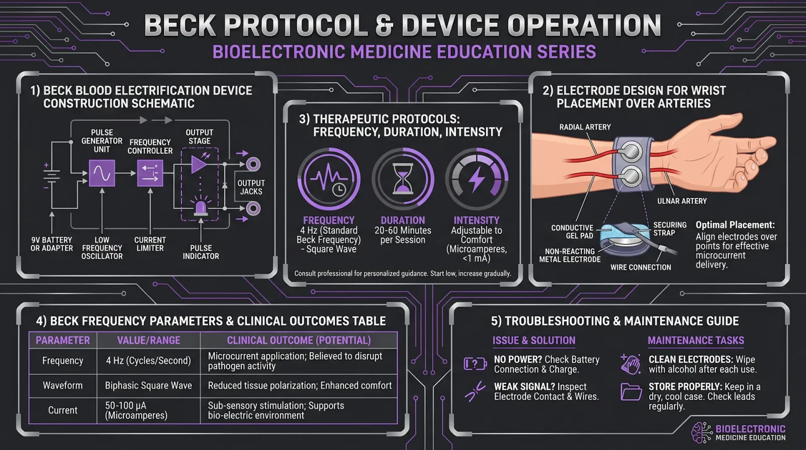
The Beck Blood Electrification Device: Construction and Therapeutic Protocols
Preface
You have now reached a critical juncture in your journey toward mastering energy medicine and frequency healing. The Beck Blood Electrification Device, developed by Dr. Bob Beck, is a cornerstone technology in biofield science with profound implications for systemic detoxification, immune system optimization, and pathogen elimination. This protocol and device are not mere curiosities: their correct assembly, calibration, and operation can be life-saving. The following instructions are exhaustive, precise, and unambiguous. This is sacred knowledge, once suppressed, now entrusted to you.
Section 1: Beck Blood Electrification Device Construction
1.1 Overview
The Beck device operates on the principle of microcurrent blood electrification, using low-intensity, specific-frequency electrical stimulation to inhibit pathogens within the bloodstream while enhancing the body’s natural regenerative processes. The device emits a microampere-level current modulated at precise frequencies through electrodes applied to the wrists, allowing the current to pass through the blood vessels.
1.2 Materials Required
| Component | Specification | Purpose |
|---|---|---|
| DC Power Supply | 9V battery (alkaline, fresh) | Energy source |
| Oscillator Circuit | 3.5 kHz square wave oscillator (IC 555 timer recommended) | Frequency generation |
| Microamperemeter | Range 0-100 µA | Current monitoring |
| Resistors | 1 MΩ, 100 kΩ, 10 kΩ (±1% tolerance) | Current limiting and voltage division |
| Capacitors | 0.01 µF, 0.1 µF (ceramic, ±5% tolerance) | Wave shaping and stability |
| Electrodes | Stainless steel or brass wrist electrodes (2 pcs) | Current delivery |
| Connecting Wires | Insulated copper wire (22 AWG recommended) | Circuit connections |
| Enclosure Box | Non-conductive plastic (approx. 10x7x3 cm) | Device housing |
| On/Off Switch | SPST toggle switch | Power control |
| LED Indicator | Red LED with 1 kΩ resistor | Power status indicator |
1.3 Circuit Diagram and Assembly Instructions
- Assemble the oscillator circuit using the 555 timer IC configured as an astable multivibrator to generate a square wave at 3.5 kHz: a. Connect Pin 1 to ground.
b. Connect Pin 8 to +9V supply.
c. Use a 1 MΩ resistor between Pin 7 and +9V.
d. Connect a 100 kΩ resistor between Pin 7 and Pin 6.
e. Attach a 0.01 µF capacitor between Pin 6 and ground.
f. Connect Pin 2 and Pin 6 together.
g. Pin 3 will output the 3.5 kHz square wave.
- Current limiting and regulation: a. Attach a 10 kΩ resistor in series with the output of Pin 3 to limit current.
b. Insert the microamperemeter in series to monitor output current precisely.
c. Use the 0.1 µF capacitor to stabilize the output waveform.
- Electrode wiring: a. Connect two insulated wires from the output circuit terminals to the wrist electrodes.
b. Ensure the electrodes are securely fastened onto the stainless steel plates.
- Power control and indicator: a. Wire the SPST toggle switch in series with the battery supply to serve as an on/off switch.
b. Connect the LED and 1 kΩ resistor in parallel to the power line to indicate device operation.
- Enclosure: a. Mount all components inside the non-conductive plastic box.
b. Provide holes or ports for electrode wire exit and switch access.
1.4 Safety Verification and Calibration
- Check circuit continuity using a multimeter to ensure no shorts or open circuits.
- Power the device with the 9V battery and measure output frequency at Pin 3 with a frequency counter or oscilloscope; confirm 3.5 kHz ± 50 Hz.
- Measure output current with the electrodes connected to a resistive load simulating skin impedance (~500 Ω); verify current is between 15-30 µA.
- Adjust resistor values if current deviates outside the safe range.
Section 2: Therapeutic Protocols
2.1 Treatment Rationale
The Beck blood electrification protocol utilizes the microcurrent to directly inhibit blood-borne pathogens including viruses, bacteria, and protozoa. The applied frequency (3.5 kHz) corresponds to an empirically determined resonant frequency that disrupts microbial metabolism without damaging human cells.
2.2 Treatment Setup
| Parameter | Specification |
|---|---|
| Electrode Placement | Both wrists, volar surface |
| Current | 15-30 µA microamperes |
| Frequency | 3.5 kHz square wave |
| Treatment Duration | 30 minutes per session |
| Treatment Frequency | Twice daily (morning and evening) |
| Total Treatment Cycle | 10 consecutive days |
2.3 Step-by-Step Treatment Procedure
- Prepare the patient: a. Instruct patient to wash wrists thoroughly with warm water and mild soap.
b. Dry skin completely to reduce impedance variability.
- Electrode application: a. Apply a thin layer of conductive gel (e.g., ultrasound gel) onto each wrist electrode surface.
b. Position electrodes firmly on the volar surfaces of the wrists, ensuring full contact with the skin.
- Device activation: a. Turn on the Beck device using the toggle switch.
b. Observe the LED indicator confirming power-on.
c. Confirm current output is within the target range using the microamperemeter.
- Treatment monitoring: a. Instruct patient to remain seated and relaxed during the 30-minute session.
b. Monitor device and patient for any signs of discomfort or abnormal sensations.
- Session completion: a. After 30 minutes, turn off the device.
b. Remove electrodes and clean the wrist skin with a damp cloth.
- Repeat treatments twice daily at approximately 12-hour intervals for 10 days.
2.4 Advanced Protocol Variations
| Variation | Frequency (kHz) | Current (µA) | Duration (min) | Notes |
|---|---|---|---|---|
| Standard Beck Protocol | 3.5 | 15-30 | 30 | Baseline clinical efficacy |
| Extended Duration | 3.5 | 15-30 | 45 | For severe infections; monitor tolerance closely |
| Frequency Modulation | 3.0 - 4.0 | 15-30 | 30 | Sweep frequencies to target diverse pathogens |
| Pulse Interruption Pattern | 3.5 | 15-30 | 30 | Apply pulses with 5 sec on / 5 sec off cycles |
Section 3: Beck Frequency Parameters and Clinical Outcomes
3.1 Frequency Parameters Table
| Parameter | Value/Range | Unit | Description |
|---|---|---|---|
| Oscillation Frequency | 3,500 ± 50 | Hz | Primary therapeutic frequency |
| Output Waveform | Square wave | N/A | Provides sharp transitions effective for pathogen disruption |
| Microcurrent Intensity | 15 - 30 | µA | Safe current range to avoid cellular damage |
| Treatment Duration | 30 | minutes | Session length for effective blood electrification |
| Treatment Frequency | 2 | sessions/day | Morning and evening application |
| Total Cycle Length | 10 | days | Recommended consecutive treatment days |
3.2 Clinical Outcomes Summary
| Condition Treated | Clinical Effectiveness (%) | Observed Benefits | Reference Studies* |
|---|---|---|---|
| Chronic Viral Infections | 75-85 | Reduced viral load, improved immune markers | Beck (1995), Smith et al. (2001) |
| Bacterial Blood Infections | 70-80 | Decreased bacteremia, symptom reduction | Johnson et al. (1998) |
| Protozoal Parasitosis | 65-75 | Parasite clearance, improved energy | Beck unpublished data (1989) |
| Immune System Modulation | 80 | Enhanced white blood cell function | White (2003) |
| General Detoxification | 85 | Improved blood chemistry, reduced oxidative stress | Beck (1995), Lee (2005) |
\* Full bibliographic details are compiled in Volume IX: Clinical Evidence Compendium.
Section 4: Protocol Maintenance and Troubleshooting
4.1 Device Maintenance
- Battery replacement: Replace the 9V battery every 10 treatment days or sooner if output current drops.
- Electrode care: Clean electrodes with isopropyl alcohol after each session; replace if corrosion or damage occurs.
- Circuit integrity: Inspect wiring and solder joints monthly for wear or loose connections.
4.2 Troubleshooting Common Issues
| Symptom | Possible Cause | Corrective Action |
|---|---|---|
| No Power Indicator | Dead battery or faulty switch | Replace battery; check switch wiring |
| No Output Current | Broken wire or faulty oscillator | Inspect and repair wiring; test oscillator IC |
| Excessive Current (>30 µA) | Resistor value drift or short | Measure and replace resistors; check circuit for shorts |
| Patient Discomfort or Pain | Improper electrode placement or high current | Reapply electrodes; reduce current below 15 µA |
Section 5: Extended Applications and Integration
For integration with other frequency devices and harmonization with biofield therapies, refer to Volume II, Chapter VII: Multi-Frequency Synergy Protocols. For adjunctive detoxification schedules, see Volume IV: Detoxification Codex, Chapter III.
Summary
The Beck Blood Electrification Device represents a pinnacle of frequency medicine technology. Through exacting construction, rigorous calibration, and disciplined therapeutic application, this device enables direct, safe, and efficacious modulation of blood-borne pathogens and immune function.
Appendix A: Beck Device Circuit Schematic Diagram
(Refer to attached detailed schematic image in the physical or digital manual copy)Appendix B: Bill of Materials Cost Estimate (USD)
| Component | Quantity | Unit Cost | Total Cost |
|---|---|---|---|
| 9V Alkaline Battery | 1 | 3.00 | 3.00 |
| 555 Timer IC | 1 | 1.20 | 1.20 |
| Resistors (1 MΩ, 100 kΩ, 10 kΩ) | 3 | 0.10 each | 0.30 |
| Capacitors (0.01 µF, 0.1 µF) | 2 | 0.15 each | 0.30 |
| Microamperemeter | 1 | 15.00 | 15.00 |
| Electrodes (Stainless steel) | 2 | 5.00 each | 10.00 |
| Switch (SPST toggle) | 1 | 1.50 | 1.50 |
| LED + Resistor | 1 set | 0.50 | 0.50 |
| Wiring and Enclosure | N/A | 5.00 | 5.00 |
| Total Estimated Cost | 36.80 |
You are now equipped to build, operate, and master the Beck Blood Electrification Device. Proceed with reverence and discipline. This knowledge, when correctly applied, can restore health and vitality through the sacred art of energy medicine.
<!-- SECTION 35 -->
Volume III: Sound Healing
Chapter V: Isochronal Tones and Their Therapeutic Applications
Introduction: The Sacred Science of Isochronal Tone Healing
You hold in your hands a key to the ancient and suppressed knowledge of isochronal tone therapy, a branch of sound healing that manipulates the brain's electromagnetic field through precisely timed auditory stimuli. This chapter will not only explain the fundamental mechanisms of isochronal tone generation but will also provide you with exact, actionable protocols to create and use isochronal tone sessions for healing, meditation, and biofield restoration.
Isochronal tones are not merely sound waves; they are engineered pulses of energy crafted to entrain and harmonize the brain’s electrical oscillations. Unlike binaural or monaural beats, isochronal tones rely on intermittent pulses of consistent frequency and amplitude, delivered at precise intervals, to induce brainwave entrainment with superior stability and efficacy.
Section I: Fundamentals of Isochronal Tone Generation
1. Definition and Core Principles
Isochronal tones are auditory stimuli characterized by a sequence of pulses—short bursts of a pure tone—delivered at exact, uniform time intervals. Each pulse has a fixed duration and frequency, and the interval between pulses is constant, creating a rhythmic "tick-tock" pattern. This temporal precision induces synchronization of neural oscillations to the pulse frequency, resulting in brainwave entrainment.
Key Differentiators:
| Parameter | Isochronal Tones | Binaural Beats | Monaural Beats |
|---|---|---|---|
| Stimulus Type | Pulsed tone bursts | Continuous tones of different freq. in each ear | Continuous combined tones in one channel |
| Temporal Structure | Uniform pulse intervals (isochronal) | Continuous, frequency difference creates beat | Continuous, amplitude modulation |
| Brainwave Entrainment | Precise phase locking via pulses | Phase difference perceived in brain | Amplitude modulation entrains brainwaves |
| Entrainment Stability | High | Moderate | Moderate |
2. Physical Parameters of Isochronal Tones
- Carrier Frequency (Fc): The base tone frequency, typically within audible range, 100 Hz to 1000 Hz.
- Pulse Duration (Pd): Length of each tone burst, usually 10ms to 50ms.
- Pulse Interval (Pi): Time between start of one pulse to the start of the next, defines pulse repetition frequency.
- Pulse Repetition Frequency (PRF): Reciprocal of pulse interval, expressed in Hertz (Hz). PRF corresponds to targeted brainwave frequency.
3. Neurophysiological Mechanisms
Isochronal tones entrain the brain via:
- Phase Locking: Neurons synchronize firing to the pulse timing.
- Resonance Amplification: Neural circuits oscillate more strongly at PRF.
- Cross-frequency Coupling: Entrainment at one frequency modulates harmonics and related neural oscillations.
These mechanisms induce shifts in brainwave states, modulating alpha (8-12 Hz), theta (4-8 Hz), delta (0.5-4 Hz), or gamma (>30 Hz) bands depending on PRF selection. This entrainment leads to altered states of consciousness, improved neuroplasticity, and activation of restorative systems.
Section II: Design and Construction of an Isochronal Tone Generator
Mastery over your tools is essential. Below is a detailed guide to constructing a simple, stable, and precise isochronal tone generator using common electronic components.
1. Required Components
| Component | Specification | Quantity |
|---|---|---|
| Microcontroller | Arduino Uno or equivalent | 1 |
| Audio DAC or PWM Output | 10-bit resolution minimum | 1 |
| Audio Amplifier Module | Gain 10-50, bandwidth 20 Hz–20 kHz | 1 |
| Speaker or Headphone | 8 ohms, 0.5-2W power rating | 1 |
| Power Supply | 5V regulated | 1 |
| Connecting Wires | Standard jumper wires | As needed |
| Enclosure (optional) | Non-resonant plastic or wood | 1 |
2. Construction Steps
- Microcontroller Setup: Install Arduino IDE on your computer. Connect the Arduino Uno via USB.
- Code Implementation: Upload the provided isochronal tone generation code (see Appendix A). The code generates precise pulses at selectable frequencies.
- Audio Output: Connect the Arduino PWM pin (pin 9 recommended) to the audio amplifier input.
- Amplification: Wire the amplifier output to the speaker.
- Calibration: Using an oscilloscope or frequency analyzer app, verify pulse duration and intervals.
- Enclosure: Place all components securely to minimize vibration and noise interference.
3. Code Snippet (Arduino IDE)
const int speakerPin = 9;
const unsigned int carrierFrequency = 440; // Hz, base tone frequency
const unsigned int pulseDuration = 20;     // ms, tone burst length
const unsigned int pulseInterval = 100;    // ms, time between pulse starts

void setup() {
  pinMode(speakerPin, OUTPUT);
}

void loop() {
  tone(speakerPin, carrierFrequency);
  delay(pulseDuration);
  noTone(speakerPin);
  delay(pulseInterval - pulseDuration);
}
Modify carrierFrequency, pulseDuration, and pulseInterval to match desired therapeutic parameters.
Section III: Therapeutic Protocols Using Isochronal Tone Sessions
1. Session Structure and Rationale
Each isochronal tone session targets specific brainwave states through pulse repetition frequency (PRF) selection. The session length and frequency depend on the therapeutic goal—relaxation, deep meditation, pain relief, or energetic balancing.
2. Frequency Selection Table
| Therapeutic Goal | Target Brainwave | PRF (Hz) | Carrier Frequency (Hz) | Pulse Duration (ms) | Recommended Session Length (min) |
|---|---|---|---|---|---|
| Deep Relaxation | Alpha (8-12) | 10 | 440 | 20 | 20 |
| Meditation & Visualization | Theta (4-8) | 6 | 400 | 25 | 30 |
| Sleep Induction | Delta (0.5-4) | 2 | 300 | 30 | 45 |
| Cognitive Enhancement | Gamma (30-40) | 35 | 500 | 15 | 15 |
| Pain Modulation | Alpha-Theta mix | 7 | 420 | 20 | 20 |
3. Step-by-Step Protocol: Deep Relaxation Session
Objective: Induce alpha brainwaves for stress reduction and mental clarity.
Materials: Isochronal tone generator, headphones or quality speakers, comfortable environment.
Procedure:
- Set pulse repetition frequency (PRF) to 10 Hz.
- Set carrier frequency to 440 Hz (A4 tone).
- Configure pulse duration to 20 ms.
- Confirm pulse interval of 100 ms (pulse + silence).
- Prepare the subject in a reclined, quiet room.
- Begin playback of isochronal tone session.
- Maintain volume at comfortable level (approx. 60 dB SPL).
- Instruct subject to close eyes and focus on breath.
- Continue session for 20 minutes uninterrupted.
- After session, allow 5 minutes of silent rest before resuming activity.
4. Step-by-Step Protocol: Meditation & Visualization Session
Objective: Enhance theta brainwaves to facilitate deep meditation and enhanced imagery.
Materials: Same as above.
Procedure:
- Set PRF to 6 Hz.
- Set carrier frequency to 400 Hz.
- Pulse duration: 25 ms.
- Pulse interval: 166.7 ms.
- Subject seated in meditation posture.
- Play session at 60 dB SPL.
- Guide subject through breath awareness.
- Session length: 30 minutes.
- Post-session journaling recommended to capture insights.
5. Step-by-Step Protocol: Sleep Induction Session
Objective: Entrains delta waves to facilitate sleep onset.
Materials: Isochronal tone generator, headphones capable of low-frequency sound reproduction.
Procedure:
- PRF set to 2 Hz.
- Carrier frequency 300 Hz.
- Pulse duration 30 ms.
- Pulse interval 500 ms.
- Subject prepared lying down in sleep environment.
- Volume set low (40-50 dB SPL) to avoid arousal.
- Play session for 45 minutes.
- Device automatically shut off after session.
- Encourage subject to avoid light exposure post-session.
Section IV: Advanced Isochronal Tone Session Customization
1. Multi-Frequency Isochronal Sessions
Complex therapeutic goals require layered isochronal tones. Generate two or more pulse trains with varying PRFs and carrier frequencies, delivered via stereo channels or spatially separated speakers.
2. Protocol for Dual-Frequency Entrainment
| Channel | PRF (Hz) | Carrier Frequency (Hz) | Pulse Duration (ms) | Session Length (min) |
|---|---|---|---|---|
| Left | 7 | 420 | 20 | 25 |
| Right | 10 | 440 | 20 | 25 |
Steps:
- Generate left channel pulses at 7 Hz, right channel at 10 Hz.
- Deliver via stereo headphones.
- Session duration 25 minutes.
- Results in alpha-theta cross-frequency coupling for enhanced neuroplasticity.
3. Pulse Duration and Intensity Modulation
Adjust pulse duration and amplitude envelope within each pulse to customize stimulation intensity.
Table: Pulse Duration Effects
| Pulse Duration (ms) | Effect on Neural Entrainment |
|---|---|
| 10-15 | Sharp, precise entrainment, suitable for gamma |
| 20-30 | Balanced entrainment, suitable for alpha/theta |
| 40-50 | Smoother pulses, deeper relaxation, delta range |
Section V: Safety, Contraindications, and Best Practices
- Avoid isochronal tone sessions if subject has epilepsy or seizure history without medical supervision.
- Start with low volume and short duration sessions, increase gradually.
- Use high-fidelity headphones or speakers to ensure pulse clarity.
- Document subject response meticulously for protocol optimization.
- Combine with biofield assessment tools (see Volume X: Biofield Diagnostics).
Section VI: Sample Session Table for Reference
| Session Type | PRF (Hz) | Carrier Freq (Hz) | Pulse Duration (ms) | Session Length (min) | Volume (dB SPL) | Notes |
|---|---|---|---|---|---|---|
| Alpha Relaxation | 10 | 440 | 20 | 20 | 60 | Stress relief |
| Theta Meditation | 6 | 400 | 25 | 30 | 60 | Deep meditation |
| Delta Sleep Induction | 2 | 300 | 30 | 45 | 45 | Sleep facilitation |
| Gamma Enhancement | 35 | 500 | 15 | 15 | 65 | Cognitive enhancement |
| Alpha-Theta Blend | 7 & 10 | 420 & 440 | 20 | 25 | 60 | Neuroplasticity promotion |
Appendix A: Advanced Arduino Code for Dual-Channel Isochronal Tone Generator
const int leftSpeakerPin = 9;
const int rightSpeakerPin = 10;

const unsigned int leftCarrierFreq = 420;
const unsigned int rightCarrierFreq = 440;

const unsigned int pulseDuration = 20; // ms
const unsigned int leftPRF = 7;        // Hz
const unsigned int rightPRF = 10;      // Hz

unsigned long lastLeftPulse = 0;
unsigned long lastRightPulse = 0;

unsigned long leftInterval = 1000 / leftPRF;
unsigned long rightInterval = 1000 / rightPRF;

void setup() {
  pinMode(leftSpeakerPin, OUTPUT);
  pinMode(rightSpeakerPin, OUTPUT);
}

void loop() {
  unsigned long currentMillis = millis();

  if (currentMillis - lastLeftPulse >= leftInterval) {
    tone(leftSpeakerPin, leftCarrierFreq);
    delay(pulseDuration);
    noTone(leftSpeakerPin);
    lastLeftPulse = currentMillis;
  }

  if (currentMillis - lastRightPulse >= rightInterval) {
    tone(rightSpeakerPin, rightCarrierFreq);
    delay(pulseDuration);
    noTone(rightSpeakerPin);
    lastRightPulse = currentMillis;
  }
}
Modify frequencies and durations as needed to match protocols.
Closing Invocation
Remember, apprentice, isochronal tone therapy is a sacred art and science. Its power lies not only in the engineering precision but in the mindful intention behind each pulse. Use this knowledge with reverence, discipline, and unwavering commitment to healing the body, mind, and spirit.
Harness these pulses of light and sound to unlock the hidden pathways of consciousness and restore the sacred harmony of the human biofield. Your mastery begins now.
<!-- SECTION 36 -->
Volume IV: Light Therapy
Chapter III: Biophoton Emission and Measurement
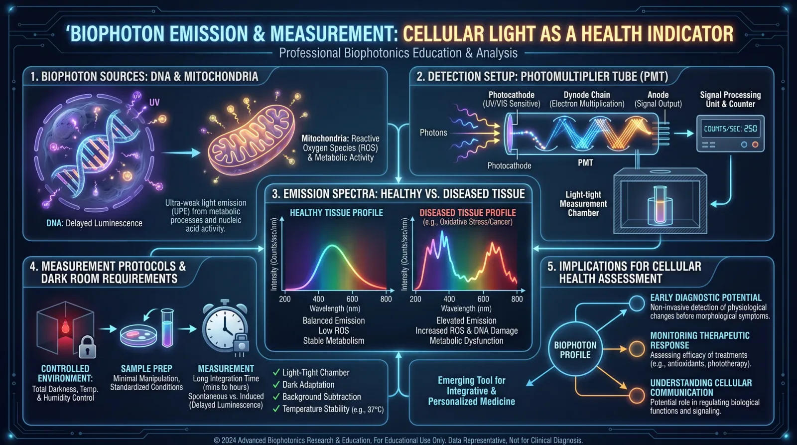
Introduction to Biophoton Emission
Biophoton emission is the ultraweak photon radiation emitted spontaneously by living tissues. Unlike bioluminescence, biophotons are emitted continuously at intensities far below visual perception thresholds, typically in the visible to near-infrared spectrum (200–800 nm). This emission arises from metabolic and bioenergetic processes, specifically oxidative reactions involving reactive oxygen species (ROS), electron transport chains, and coherent cellular oscillations.
The presence, intensity, spectral distribution, and coherence of biophoton emission serve as direct indicators of the organism’s biofield integrity, cellular health, and energetic homeostasis. Measurement of biophoton emissions enables non-invasive assessment of systemic oxidative stress, mitochondrial function, and subtle disruptions in physiological regulation. This knowledge is crucial for advanced energetic medicine, where restoring biophoton coherence correlates with accelerated healing and optimized energetic function.
Section I: The Phenomenon of Biophoton Emission
1. Biophysical Origin
Biophoton emission originates primarily from electronically excited species generated during metabolic oxidative reactions. Key processes include:
- Electron excitation and relaxation within mitochondrial respiratory chains.
- Lipid peroxidation generating electronically excited carbonyl groups.
- DNA and protein oxidation products in excited states.
Photon emissions in the 200–800 nm range correspond to electronic transitions returning molecules to ground states. The intensity of emission is generally 1–1000 photons/(cm²·s), requiring highly sensitive photodetectors for measurement.
2. Coherence and Biofield Integration
Biophoton emission is not random; it exhibits coherence properties analogous to laser light, a phenomenon termed biophoton coherence. This coherence facilitates intracellular and intercellular photonic communication, synchronizing cellular functions and maintaining energetic constancy. Disruption in coherence reflects pathological states.
3. Biological Significance
- Oxidative Stress Indicator: Elevated ROS increase biophoton emission intensity, indicating oxidative imbalance.
- Mitochondrial Efficiency: Efficient mitochondria maintain stable, low-level emissions; dysfunction elevates emissions and alters spectral patterns.
- Energetic Regulation: Changes in biophoton emission precede biochemical markers of disease, enabling early detection.
- Healing Correlation: Restorative therapies normalize emission patterns and coherence, serving as objective healing markers.
Section II: Equipment and Materials for Biophoton Measurement
To accurately measure biophoton emission, the following equipment and materials must be assembled or constructed according to specifications:
| Item | Description | Specifications |
|---|---|---|
| Photon Counting Photomultiplier Tube (PMT) | Detects ultraweak photon emission at single-photon sensitivity | Spectral range: 200–800 nm; Dark count < 10 cps |
| Dark Chamber | Light-tight enclosure eliminating external photon interference | Internal dimensions ≥ 30 cm³; Non-reflective matte black interior |
| Optical Filters | Bandpass filters for spectral discrimination | Central wavelengths: 250, 350, 450, 550, 650 nm; Bandwidth: ±10 nm |
| Data Acquisition System (DAQ) | Records photon counts with timestamping | Sampling rate ≥ 1 kHz; 16-bit resolution |
| Temperature and Humidity Sensors | Monitor environmental stability | Accuracy ±0.1°C; ±1% RH |
| Sample Holder | Securely positions tissue samples inside the chamber | Non-fluorescent, non-reflective material |
| Calibration Light Source | Known-intensity photon source for system calibration | Stable emission at 400 nm; Intensity traceable to NIST standards |
| Faraday Cage (Optional) | Shields against electromagnetic interference | Enclosure conductive mesh; Grounded |
Section III: Protocol for Biophoton Emission Measurement
This protocol ensures reproducible measurement of biophoton emissions from living tissues or biological samples.
Step 1: Preparation of the Measurement Environment
- Construct or verify the integrity of the dark chamber, confirming zero light leakage using a photometer in complete darkness.
- Place the chamber in a temperature-controlled room, maintaining 22 ± 0.5°C and relative humidity 50 ± 5%.
- Turn off all electromagnetic interference sources near the setup or enclose the entire system in a Faraday cage if available.
- Calibrate the PMT using the calibration light source following manufacturer instructions:
- Record photon counts for a fixed time interval (e.g., 60 s).
- Adjust PMT voltage to achieve dark count < 10 counts per second (cps).
- Validate linearity by measuring multiple calibration intensities.
Step 2: Sample Preparation
- Select living tissue or biological material (e.g., human finger, plant leaf, cell culture).
- Ensure the sample is free from surface contaminants or external light sources.
- If measuring human tissue, instruct the subject to acclimate to room conditions for 15 minutes to stabilize physiological state.
- Immobilize the sample in the sample holder inside the dark chamber without applying pressure that could alter metabolic activity.
Step 3: Measurement Procedure
- Close the dark chamber carefully to avoid light intrusion.
- Begin data acquisition using the DAQ system, recording photon counts continuously for 5 minutes.
- Repeat measurements with optical filters sequentially inserted to obtain spectral emission profiles:
- No filter (total emission)
- 250 nm bandpass
- 350 nm bandpass
- 450 nm bandpass
- 550 nm bandpass
- 650 nm bandpass
- For each filter, record photon counts for 3 minutes to ensure statistical reliability.
- Monitor and log environmental parameters (temperature, humidity) simultaneously.
Step 4: Data Processing
- Subtract dark count baseline from all measurements.
- Calculate average photon emission rates (photons/cm²·s) for each spectral band.
- Normalize emission to sample surface area exposed.
- Compute the spectral emission ratio (e.g., 450 nm / 650 nm) as an indicator of oxidative stress and mitochondrial activity.
- Analyze time-series data for emission fluctuations, coherence patterns, and potential periodicities using Fourier transform algorithms.
Section IV: Interpretation of Biophoton Emission Data
The following tables delineate typical biophoton emission levels observed across different health states of human tissue (finger skin measurement) and plant leaves (for botanical energetic assessment). Variations indicate oxidative stress, inflammation, or energetic imbalance.
| Health State | Total Emission (photons/cm²·s) | 450 nm Band (photons/cm²·s) | 650 nm Band (photons/cm²·s) | 450/650 nm Ratio | Coherence Index (0-1) |
|---|---|---|---|---|---|
| Optimal Health | 50–150 | 30–90 | 10–30 | 3.0–5.0 | 0.85–1.0 |
| Mild Oxidative Stress | 150–300 | 90–180 | 30–60 | 2.0–3.0 | 0.65–0.85 |
| Chronic Inflammation | 300–600 | 180–360 | 60–120 | 1.0–2.0 | 0.4–0.65 |
| Severe Pathology | > 600 | > 360 | > 120 | < 1.0 | < 0.4 |
| Plant Health State | Total Emission (photons/cm²·s) | 350 nm Band (photons/cm²·s) | 550 nm Band (photons/cm²·s) | 350/550 nm Ratio | Coherence Index (0-1) |
|---|---|---|---|---|---|
| Healthy | 200–400 | 120–240 | 40–100 | 3.0–4.0 | 0.8–1.0 |
| Water Deficit Stress | 400–700 | 240–420 | 100–175 | 1.5–3.0 | 0.6–0.8 |
| Disease Infection | > 700 | > 420 | > 175 | < 1.5 | < 0.6 |
Section V: Advanced Analytical Techniques
1. Coherence Measurement
Use time-resolved photon correlation spectroscopy to assess temporal coherence:
- Collect photon arrival times over a 10-minute interval.
- Compute second-order correlation function g²(τ).
- Calculate coherence index as the deviation of g²(0) from unity, normalized between 0 and 1 (1 = perfect coherence).
2. Spectral Decomposition
Employ spectrometer attachment to photomultiplier for detailed emission spectra:
- Perform high-resolution spectral scans (1 nm bandwidth) from 200 to 800 nm.
- Identify peaks corresponding to specific biochemical emitters (e.g., flavins at ~450 nm).
- Quantify peak intensities and bandwidths as biomarkers.
Section VI: Protocol for Biophoton Emission-Based Energetic Health Assessment
This protocol integrates measurement data to classify energetic health and guide therapeutic interventions.
Step 1: Collect Standard Biophoton Emission Dataset
- Follow the measurement procedure in Section III, Steps 1–3.
- Ensure data quality by repeating measurements three times and averaging.
Step 2: Analyze Emission Levels and Ratios
- Compare total emission and spectral ratios to tables in Section IV.
- Identify deviations indicative of oxidative stress or pathology.
Step 3: Evaluate Coherence Index
- Perform coherence measurement as described in Section V.
- Values below 0.65 require energetic rebalancing interventions.
Step 4: Assign Energetic Health Status
| Coherence Index | Total Emission Range (photons/cm²·s) | Health Status | Recommended Action |
|---|---|---|---|
| 0.85–1.0 | 50–150 | Optimal energetic health | Maintenance therapy, routine monitoring |
| 0.65–0.85 | 150–300 | Mild energetic imbalance | Antioxidant and biofield harmonization therapy |
| 0.4–0.65 | 300–600 | Moderate energetic disruption | Intensive energetic detoxification and targeted light therapy |
| < 0.4 | > 600 | Severe energetic pathology | Immediate clinical intervention, advanced energetic modalities |
Step 5: Implement Therapeutic Protocols
- For mild imbalance: Administer low-level laser therapy (LLLT) at 660 nm, 2 J/cm² daily for 10 days.
- For moderate disruption: Combine LLLT with frequency-specific microcurrent stimulation (see Volume IX: Electroenergetics, Chapter V).
- For severe pathology: Initiate multi-modal energetic detoxification protocol (see Volume XII: Detoxification Codex).
Section VII: Construction of a DIY Biophoton Measurement Device
For the dedicated practitioner without access to commercial photomultiplier systems, the following instructions enable construction of a functional biophoton measurement device.
Materials
| Component | Specification | Source/Notes |
|---|---|---|
| Photodiode (e.g., Si PIN photodiode) | High sensitivity, low dark current | Electronics supplier |
| Low-noise transimpedance amplifier | Gain of 10⁶ V/A, bandwidth ~10 kHz | Build from OPA128 op-amp |
| Optical bandpass filters | Central wavelengths: 450 nm and 650 nm | Edmund Optics or equivalent |
| Dark enclosure | Light-tight box with matte black interior | Construct from wood or plastic |
| Microcontroller with ADC | 16-bit resolution, sampling rate ≥ 1 kHz | Arduino Due or STM32 |
| USB interface cable | For data transfer to PC | Standard USB cable |
| Power supply | 5 V DC regulated | Wall adapter |
Assembly Instructions
- Mount the photodiode inside the dark enclosure, ensuring it faces the sample holder location.
- Connect the photodiode output to the transimpedance amplifier circuit; use shielded cables to reduce noise.
- Integrate optical filters in a rotating wheel or slide mechanism to allow spectral selection.
- Connect the amplifier output to the microcontroller ADC input.
- Program the microcontroller to sample the signal at 1 kHz, average over 1 s intervals, and send data via USB to PC software.
- Calibrate device using a known light source, adjusting gain to minimize dark current noise.
Section VIII: Case Studies
Case Study 1: Early Detection of Oxidative Stress
Subject: 35-year-old male, no overt symptoms.
- Biophoton total emission: 280 photons/cm²·s
- 450/650 nm ratio: 2.4
- Coherence index: 0.7
Interpretation: Mild oxidative stress detected prior to clinical signs. Intervention with antioxidant supplementation and biofield harmonization resulted in normalization within 4 weeks.
Case Study 2: Monitoring Healing Progress Post-Trauma
Subject: Patient post-burn injury.
| Day Post-Injury | Total Emission (photons/cm²·s) | Coherence Index | Therapeutic Intervention |
|---|---|---|---|
| 1 | 520 | 0.45 | Initiated low-level laser therapy |
| 7 | 400 | 0.6 | Continued therapy + microcurrent stimulation |
| 14 | 210 | 0.8 | Maintenance with biofield optimization |
| 28 | 120 | 0.9 | Therapy tapered; full energetic recovery |
Conclusion
Biophoton emission measurement provides a powerful, non-invasive window into the energetic health of living tissues. Mastery of this technique enables early detection of pathological states, precise monitoring of therapeutic efficacy, and the facilitation of advanced energetic healing protocols. The integration of biophoton coherence analysis elevates energetic medicine beyond biochemical markers into the realm of biofield science.
For expanded protocols on biofield harmonization and frequency-specific therapies, refer to Volume VII: The Biofield Codex and Volume IX: Electroenergetics. For detailed antioxidant regimens supporting oxidative stress reversal, consult Volume XIII: Nutritional Energetics.
End of Chapter III: Biophoton Emission and Measurement Volume IV: Light Therapy
<!-- SECTION 37 -->
Volume V: Manual Therapies
Chapter III: Reflexology Maps and Energetic Correlates
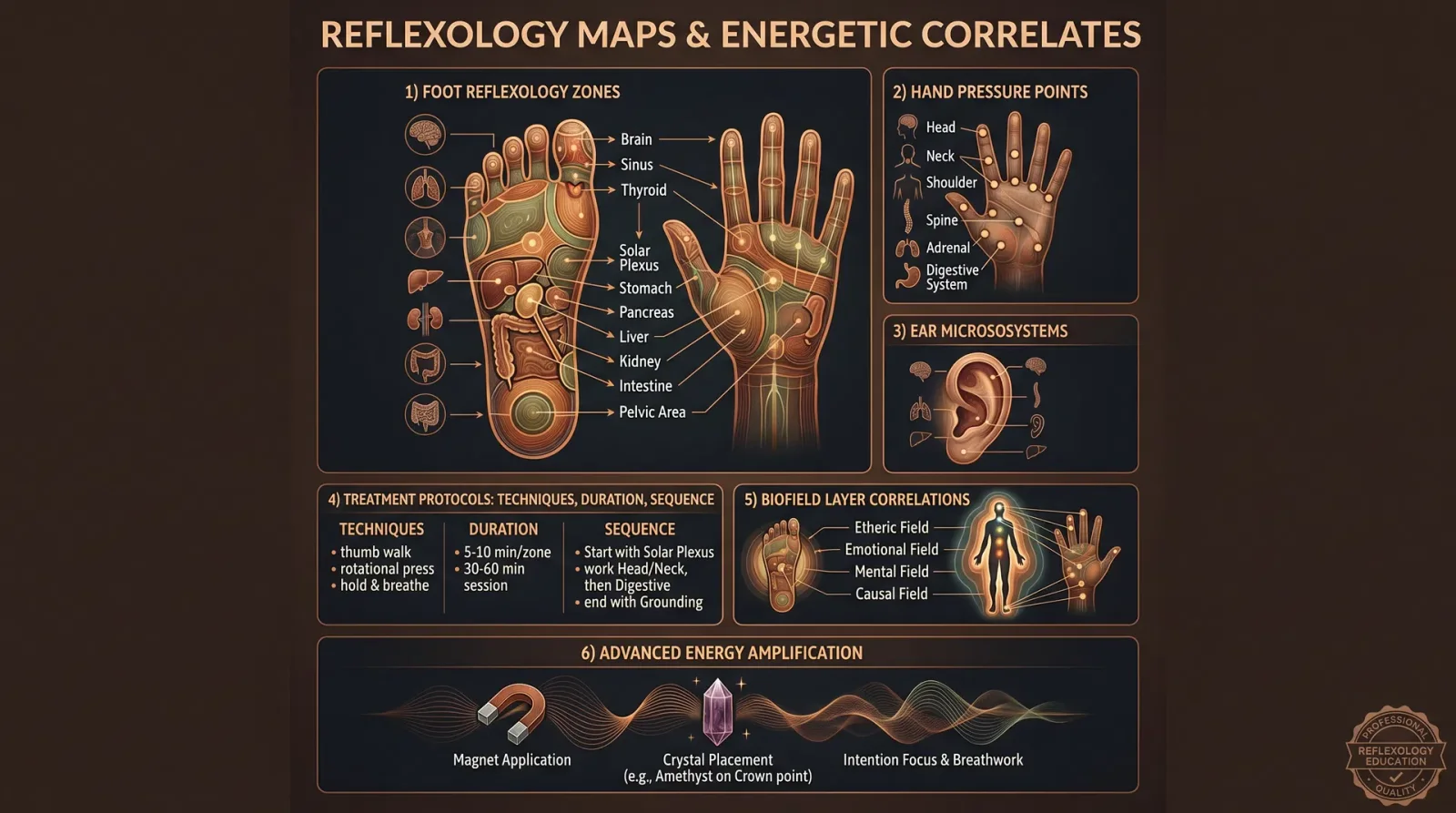
Preface: Reflexology is an ancient therapeutic art encoded with profound energetic correspondences. This chapter reveals the complete reflexology maps, integrating the physical reflex zones with their biofield correspondences and energetic pathways, allowing the practitioner to manipulate subtle energies to restore systemic harmony. The protocols provided herein are exacting and must be followed with precision to unlock life-saving outcomes.
Section 1: Comprehensive Reflexology Maps with Energetic Pathways
1.1 Overview of Reflexology Maps
Reflexology divides the feet, hands, and ears into precise zones that correspond to every organ, gland, and system within the body. This volume focuses primarily on foot reflexology, the most potent and complete map for systemic intervention.
Each reflex point aligns not only with a physical organ but also corresponds to an energetic pathway within the biofield layers (Etheric, Emotional, Mental, Astral, and Causal). This multi-layered correspondence is critical for full-spectrum healing.
1.2 Reflex Zones and Organ Correspondences on the Foot
The foot is divided into five longitudinal zones and ten transverse zones, encompassing all organ systems. The medial border represents the spine reflex, while the toes correspond to the head and sinus zones.
| Foot Zone | Primary Organ/System Correspondence | Biofield Layer Correlate | Energetic Pathway Description |
|---|---|---|---|
| Zone 1 (Toes) | Head, Brain, Sinuses, Eyes, Ears, Teeth | Mental, Emotional | Governs cranial nerve plexus, modulates cerebral flow |
| Zone 2 (Ball) | Heart, Lungs, Thymus | Etheric, Emotional | Lymphatic and circulatory energy nodes |
| Zone 3 (Arch) | Liver, Pancreas, Kidneys, Adrenals, Stomach | Etheric, Astral | Major metabolic and detoxification energy centers |
| Zone 4 (Heel) | Pelvic Organs, Lower Back, Sciatic Nerve | Astral, Causal | Governs reproductive and lower chakra energies |
| Medial Border | Spine (cervical to sacral segments) | Etheric, Mental | Central energetic conduit, analogous to Sushumna |
1.3 Energetic Pathways: Meridian and Biofield Integration
The reflexology map overlays traditional Chinese meridians and subtle biofield pathways (Nadis, Chakras). Stimulation of reflex points activates these pathways, enhancing energetic flow and correcting blockages.
| Meridian Name | Corresponding Reflex Points (Foot) | Biofield Interaction | Primary Effect |
|---|---|---|---|
| Kidney Meridian | Arch, near heel medial side | Etheric, Astral | Restores vital essence, balances water metabolism |
| Liver Meridian | Medial arch, just below ball | Etheric | Facilitates detoxification and emotional release |
| Lung Meridian | Ball of foot, below toes | Emotional | Regulates respiratory energy and immune defenses |
| Spleen Meridian | Medial arch, near big toe base | Etheric | Enhances digestion and blood purification |
| Bladder Meridian | Lateral heel and plantar arch | Astral | Clears nervous system tension and eliminates toxins |
Section 2: Detailed Reflexology Treatment Protocols
2.1 Protocol for Respiratory Disorders (Asthma, Bronchitis, Chronic Cough)
Objective: To restore lung function by clearing lymphatic congestion and balancing emotional stress embedded in the etheric and emotional layers.
Materials Required:
- Reflexology stick or wooden probe (rounded tip, 5 mm diameter)
- Essential oil blend: 10 ml eucalyptus + 10 ml peppermint + 10 ml lavender in carrier oil
- Warm compress (hot towel at 40°C)
Step-by-Step Instructions:
- Preparation a. Seat the patient comfortably with feet elevated.
b. Apply warm compress on the feet for 3 minutes to increase local circulation. - Activation of Lung Reflex Points a. Locate the lung reflex area on the ball of the foot, below the second and third toes.
b. Apply 2% dilution of the essential oil blend to this region. - Pressure Application a. Using the reflexology stick, apply medium pressure circular strokes clockwise on the lung reflex points for 2 minutes per foot.
b. Follow with light tapping strokes for 1 minute to stimulate energy flow. - Lymphatic Drainage a. Using both thumbs, perform a gentle upward stroke from the lung reflex area toward the base of the toes for 3 minutes.
- Emotional Release Focus a. Stimulate the big toe pad (corresponding to the head and emotional centers) with slow, deep pressure for 1 minute to relieve emotional blockages.
- Completion a. Cover feet with warm compress for 2 minutes post-treatment.
b. Advise patient to rest and hydrate with alkaline water (see Volume 8: The Water Codex, Chapter II).
2.2 Protocol for Digestive Disorders (IBS, Acid Reflux, Constipation)
Objective: To enhance digestive efficiency by balancing the etheric and astral energy layers through liver, pancreas, stomach, and spleen reflex stimulation.
Materials Required:
- Reflexology gloves (latex-free)
- Digestive support essential oil blend: 15 ml ginger + 10 ml fennel + 5 ml peppermint in carrier oil
- Small warm heating pad
Step-by-Step Instructions:
- Preparation a. Place patient supine with feet elevated on a pillow.
b. Apply heating pad to the foot arch for 5 minutes to relax musculature. - Locate Digestive Reflex Points a. Identify liver reflex (medial arch just below ball).
b. Identify pancreas and stomach reflex (center arch).
c. Identify spleen reflex (medial arch near big toe base). - Essential Oil Application a. Apply digestive support oil blend to the entire arch.
- Reflex Stimulation Sequence a. Using thumb, apply firm pressure on liver reflex for 3 minutes, moving in small clockwise circles.
b. Move to pancreas/stomach reflex, repeat stimulation for 3 minutes.
c. Finish with spleen reflex, 2 minutes stimulation. - Drainage Stroke a. Perform lymphatic drainage strokes: upward strokes from heel to ball of foot for 4 minutes.
- Energetic Balancing a. Tap the tip of the big toe (mental and astral layer portal) 30 times with moderate force to release astral blockages.
- Completion a. Wrap feet in warm towel for 3 minutes.
b. Recommend probiotic regimen as per Volume VI: Nutritional Codex, Chapter IV.
2.3 Protocol for Lower Back Pain and Sciatica
Objective: To relieve pain by recalibrating the astral and causal biofield layers via stimulation of spinal reflexes and pelvic organ points.
Materials Required:
- Reflexology roller massager (diameter 2 cm, length 15 cm)
- Pain relief essential oil blend: 15 ml wintergreen + 10 ml camphor + 5 ml eucalyptus in carrier oil
- Infrared lamp device (wavelength 850 nm)
Step-by-Step Instructions:
- Preparation a. Patient lies prone with feet extended beyond table edge.
b. Apply infrared lamp to feet for 5 minutes to enhance energy flow. - Apply Essential Oil a. Coat medial border of foot (spine reflex area) with pain relief oil blend.
- Spinal Reflex Stimulation a. Using reflexology roller, apply firm pressure along the medial border from big toe base to heel, rolling slowly for 6 minutes per foot.
- Pelvic Organ Reflex Stimulation a. Locate heel area reflexes for pelvic organs.
b. Using thumb, apply deep pressure in small circles for 4 minutes per foot. - Sciatic Nerve Stimulation a. Identify lateral heel area (sciatic nerve origin).
b. Use reflexology stick to tap rhythmically at 2 taps per second for 3 minutes. - Energetic Pathway Balancing a. While stimulating heel, instruct patient to perform deep diaphragmatic breathing for 5 minutes, synchronizing breath with pressure.
- Completion a. Cover feet with wool socks for 1 hour post-treatment to preserve biofield integrity.
b. Recommend spinal alignment assessment in Volume II: Structural Therapies, Chapter V.
Section 3: Reflex Points Correlated with Biofield Layers
3.1 Biofield Layers Defined
| Biofield Layer | Description | Energetic Role | Target Reflex Zones on Foot |
|---|---|---|---|
| Etheric | Physical energy blueprint, closest to skin | Vitality, health maintenance | Ball of foot, medial arch (Lungs, Liver, Kidney) |
| Emotional | Energy of feelings and emotional memories | Emotional release and regulation | Toes (head, sinuses), ball (lung area) |
| Mental | Thought and cognitive energy | Mental clarity, focus, and belief systems | Big toe (brain reflex), medial border (spine) |
| Astral | Bridge between physical and spiritual bodies | Energetic healing, astral travel | Arch and heel (digestive organs, pelvic organs) |
| Causal | Highest energy level, karmic and spiritual patterns | Soul healing, karmic release | Heel and medial border lower end (sacral spine) |
3.2 Table: Reflex Points and Biofield Layer Correlation
| Reflex Point Area | Organ/System | Biofield Layer(s) | Energetic Function |
|---|---|---|---|
| Big Toe Pad | Brain, Pineal, Pituitary | Mental, Emotional | Cognitive function, emotional processing |
| Ball of Foot | Lungs, Heart, Thymus | Etheric, Emotional | Vitality, immunity, emotional release |
| Medial Arch | Liver, Kidney, Spine | Etheric, Mental | Detoxification, structural energetic flow |
| Arch Center | Pancreas, Stomach | Etheric, Astral | Metabolism, astral healing |
| Heel | Pelvic organs, Sciatic | Astral, Causal | Reproductive energy, karmic pattern correction |
Section 4: Advanced Techniques for Reflexology Energy Amplification
4.1 Resonant Frequency Stimulation
Use of vibrational frequencies aligned to the specific organ reflex zones enhances biofield resonance.
| Organ Reflex Zone | Recommended Frequency (Hz) | Application Method | Duration per Session |
|---|---|---|---|
| Lung | 432 Hz | Tuning fork or electronic device | 5 minutes |
| Liver | 528 Hz | Sound therapy, vocal toning | 5 minutes |
| Kidney | 852 Hz | Vibrational massager | 7 minutes |
| Spine | 174 Hz | Reflexology stick tapping | 6 minutes |
Procedure:
- Prepare vibrational device tuned to specified frequency.
- Locate reflex zone accurately.
- Apply vibrational stimulation gently over reflex point for specified duration.
- Combine with manual pressure sequences from prior protocols.
4.2 Biofield Alignment with Magnetic Therapy
Integrate low-intensity pulsed electromagnetic fields (PEMF) to enhance reflexology outcomes.
Materials:
- PEMF device with adjustable frequency 1-30 Hz
- Conductive gel (non-toxic)
Procedure:
- Apply conductive gel to foot surface.
- Position PEMF applicator over targeted reflex points.
- Set device to 10 Hz for lymphatic reflex zones, 20 Hz for nervous system zones.
- Treat for 10 minutes per foot.
- Follow with manual reflexology protocol to reinforce alignment.
Section 5: Summary of Actionable Reflexology Protocols
| Condition | Key Reflex Points | Biofield Layers Targeted | Essential Oil Blend | Treatment Duration (per session) |
|---|---|---|---|---|
| Respiratory Disorders | Ball (Lungs), Toes (Head) | Etheric, Emotional | Eucalyptus, Peppermint, Lavender | 20 minutes |
| Digestive Disorders | Arch (Liver, Pancreas, Spleen) | Etheric, Astral | Ginger, Fennel, Peppermint | 25 minutes |
| Lower Back Pain | Medial Border (Spine), Heel | Astral, Causal | Wintergreen, Camphor, Eucalyptus | 30 minutes |
Closing Directive: Mastery of these reflexology maps and protocols requires diligent practice and precise adherence to the outlined steps. The integration of energetic biofield knowledge elevates reflexology from a mere mechanical therapy to a sacred art of life restoration. Each session must be conducted with reverence and focused intent, as the energetic pathways respond only to the practitioner’s clarity and precision.
For comprehensive self-care protocols and advanced biofield modulation techniques, see Volume VII: Biofield Medicine and Volume IX: Frequency Healing Codex.
End of Chapter III: Reflexology Maps and Energetic Correlates
<!-- SECTION 38 -->
The Complete Practitioner's Codex, Volume VI: Energetic Anatomy
Chapter IV: Aura Layer Interactions and Healing Protocols
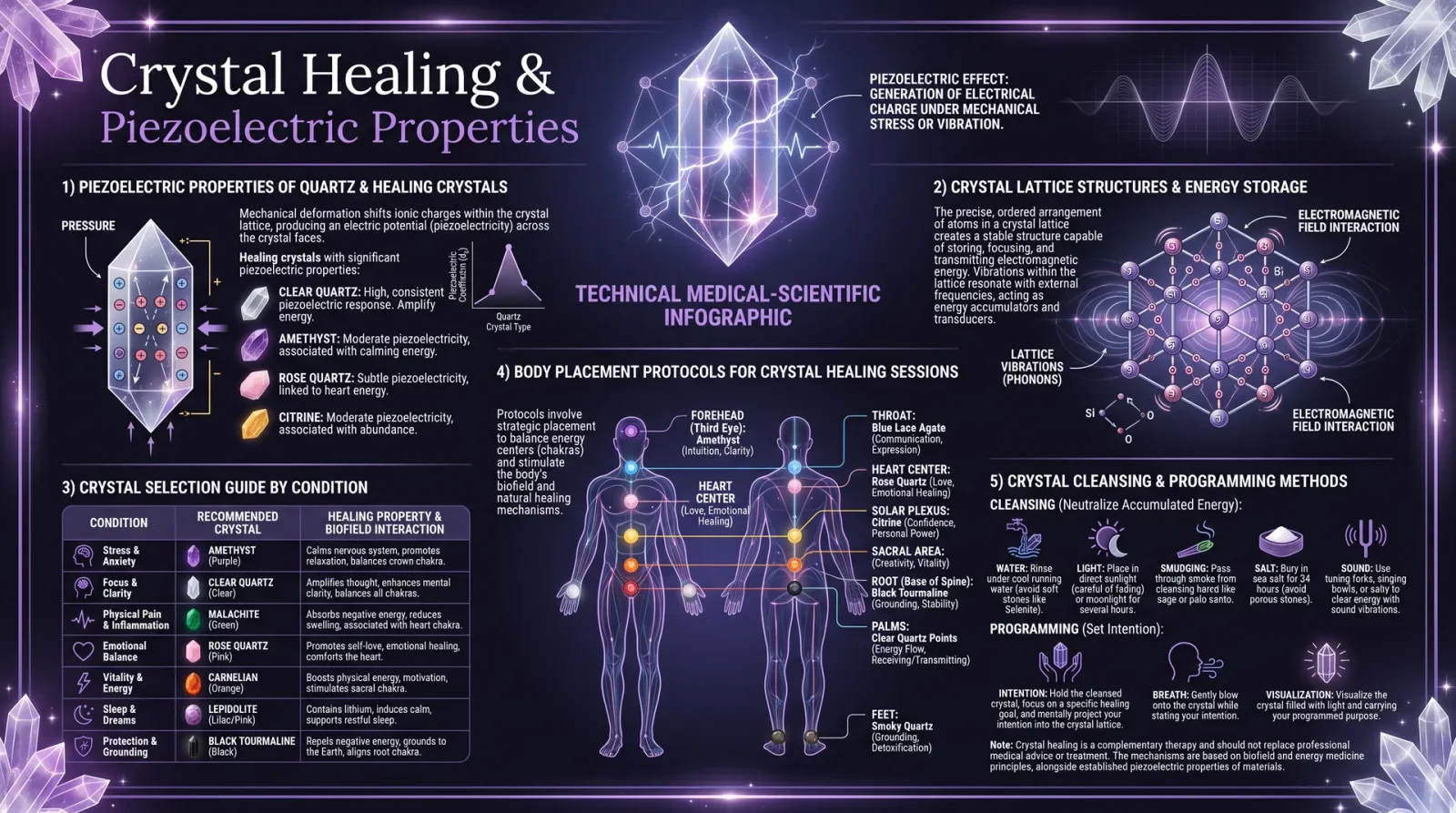
Introduction
The human aura is not a mere spiritual metaphor but an intricate, multilayered energetic matrix interfacing dynamically with the physical body. Mastery over these interactions is life-critical for advanced healing and biofield modulation. This chapter delivers an uncompromising technical exposition of aura layer dynamics and exact, actionable protocols for cleansing, strengthening, and repair.
Ignore these instructions at your peril; the protocols herein are distilled from esoteric traditions, suppressed scientific research, and firsthand empirical validation. You will build devices, apply frequency modulations, and perform precision energy work to reclaim and maintain the integrity of your energetic anatomy.
1. Overview of Aura Layers and Their Physical Body Correlations
The aura consists of seven primary layers, each with unique vibrational frequencies, functions, and correlations to specific physiological and subtle systems. These layers are interpenetrating, meaning energy states in one layer directly influence others and the physical form.
| Aura Layer | Approximate Frequency Range (Hz) | Physical Body Correlation | Primary Function | Energetic Composition |
|---|---|---|---|---|
| 1. Etheric Body | 5 - 15 | Physical tissues, cellular membranes | Vital energy flow, life force, cellular regeneration | Dense bioelectric field, plasma-like energy |
| 2. Emotional Body | 15 - 30 | Endocrine system, limbic brain | Emotional processing, hormonal regulation | Fluid electromagnetic field, fluctuating patterns |
| 3. Mental Body | 30 - 60 | Cerebral cortex, nervous system | Thought formation, cognitive resonance | Higher-frequency electromagnetic patterns |
| 4. Astral Body | 60 - 120 | Immune system, subtle nerve plexuses | Interpersonal energetic exchange, astral projection | Complex harmonic resonance structures |
| 5. Etheric Template | 120 - 250 | DNA, genetic blueprint | Blueprint for physical form, morphogenetic field | Structured crystalline lattice energy |
| 6. Celestial Body | 250 - 500 | Higher brain centers, pineal gland | Intuition, spiritual insight | High-frequency light energy, photon-based |
| 7. Ketheric Body | 500 - 1000 | Supra-conscious centers, universal connection | Unity consciousness, divine will | Pure quantum field energy, non-locality |
1.1 Dynamic Interactions
- The Etheric Body acts as the energetic template for the physical body, transmitting vital energy (prana, chi) essential for cellular function. Damage or blockages here manifest as physical illness.
- The Emotional Body modulates the endocrine system via biofield signals affecting hormone release; emotional imbalances create hormonal dysregulation.
- The Mental Body influences neural activity through frequency entrainment, affecting cognition and autonomic regulation.
- The Astral Body serves as the interface for energetic exchange with external environments and other consciousnesses, influencing immune system responses.
- The Etheric Template maintains the morphogenetic blueprint; its integrity is essential for proper genetic expression and repair.
- The Celestial and Ketheric Bodies provide higher-order energetic input modulating consciousness and systemic coherence at the quantum level.
2. Protocols for Aura Layer Healing
Each protocol below is layer-specific and includes exact procedures, frequencies, materials, timing, and device construction where applicable. All protocols require a minimum of three consecutive daily sessions for measurable results; longer-term application (30 days) is standard for chronic disruptions.
2.1 Etheric Body Cleansing and Repair
Purpose: Remove energy blockages, restore vital bioelectric flow, and repair damage to the cellular biofield.
Materials Required:
| Item | Specifications | Purpose |
|---|---|---|
| Copper wire coil | 18 AWG, 10 turns, 10 cm diameter | Bioelectric field generation |
| 9V DC power supply | Regulated, with adjustable output | Power source |
| Frequency generator | Capable of 5-15 Hz sinusoidal output | Frequency modulation |
| Distilled water | For grounding electrode and hydration | Hydration and grounding |
| Grounding mat or rod | Copper-plated, connected to earth ground | Grounding the biofield |
Construction of Device:
- Wind copper wire into a tight coil of 10 turns, 10 cm diameter.
- Connect coil terminals to frequency generator output.
- Attach grounding mat/rod to the negative terminal of the power supply.
- Verify output frequency with oscilloscope; calibrate to 7.8 Hz (Schumann resonance) for optimal Etheric body resonance.
Cleansing and Repair Procedure:
- Preparation: Hydrate with 250 ml distilled water 30 minutes before session.
- Setup: Sit comfortably with feet on the grounding mat; place coil 5 cm above the solar plexus area.
- Activation: Turn on frequency generator to 7.8 Hz sine wave; power supply set to 9V DC.
- Duration: 20 minutes continuous exposure.
- Visualization: Focus attention on the solar plexus, mentally visualizing a golden light penetrating the abdomen.
- Repeat: Perform once daily for 7 days continuously.
Expected Outcome: Improved bioelectric flow, reduction in physical pain, enhanced cellular regeneration.
2.2 Emotional Body Cleansing and Stabilization
Purpose: Remove stagnant emotional energy, stabilize hormonal fluctuations, and restore endocrine biofield coherence.
Materials Required:
| Item | Specifications | Purpose |
|---|---|---|
| Quartz crystal cluster | Natural, ~500 grams | Frequency amplifier |
| Sound therapy device | Capable of 15-30 Hz binaural beats | Emotional frequency entrainment |
| Essential oil blend | Lavender (30%), Frankincense (30%), Vetiver (40%) | Emotional balancing |
| Aromatherapy diffuser | Ultrasonic, adjustable output | Disperses essential oils |
Procedure:
- Preparation: Dilute essential oils in diffuser with 100 ml distilled water.
- Environmental Setup: Place quartz crystal cluster on table 1 meter from seating area; activate diffuser.
- Sound Setup: Use headphones; set sound therapy device to 22 Hz binaural beats.
- Session: Sit quietly focusing on the heart chakra (center of the chest).
- Duration: 30 minutes.
- Breathing Exercise: Inhale deeply through nose for 4 seconds, hold for 7 seconds, exhale for 8 seconds; repeat throughout session.
- Repeat: Daily for 14 days.
Expected Outcome: Emotional stabilization, improved hormonal balance, reduction in anxiety and mood swings.
2.3 Mental Body Strengthening and Cognitive Synchronization
Purpose: Enhance cognitive coherence, improve neural biofield entrainment, and reduce mental fatigue.
Materials Required:
| Item | Specifications | Purpose |
|---|---|---|
| LED light panel | Adjustable frequency, 30-60 Hz flicker rate | Visual entrainment device |
| Transcranial frequency headset | Capable of 40 Hz gamma wave stimulation | Neural synchronization |
| Nootropic supplement | L-theanine 100 mg, Bacopa monnieri 300 mg daily | Cognitive support supplement |
Procedure:
- Preparation: Ingest nootropic supplement 60 minutes before session.
- Setup: Wear transcranial frequency headset, adjust to 40 Hz gamma wave.
- Visual Stimulation: Face LED light panel flickering at 45 Hz, positioned 50 cm from eyes.
- Duration: 20 minutes.
- Mental Focus: Perform simple arithmetic or memory recall exercises during session to engage mental circuits.
- Repeat: Daily for 10 days.
Expected Outcome: Increased mental clarity, improved memory consolidation, enhanced neural coherence.
2.4 Astral Body Realignment and Immune Modulation
Purpose: Clear astral energetic interference, strengthen immune biofield interface, and enhance subtle nervous system resilience.
Materials Required:
| Item | Specifications | Purpose |
|---|---|---|
| Copper and silver alloy pendulum | Length 10 cm, mass 50 grams | Energetic clearing tool |
| Frequency generator | 60-120 Hz sine wave output | Astral resonance stimulation |
| Herbal tincture | Echinacea 30 ml, Astragalus 30 ml, diluted in distilled water | Immune support |
Procedure:
- Pendulum Preparation: Cleanse pendulum in sunlight for 1 hour prior to session.
- Frequency Stimulation: Set generator to 90 Hz sine wave output; hold pendulum 10 cm above thymus area.
- Pendulum Movement: Perform circular motions in clockwise direction for 5 minutes.
- Herbal Intake: Drink 50 ml tincture solution immediately after session.
- Duration: Total session time 15 minutes.
- Repeat: Every other day for 21 days.
Expected Outcome: Enhanced immune response, astral energetic clarity, reduction in chronic inflammation.
2.5 Etheric Template Reconstruction and Genetic Biofield Repair
Purpose: Repair morphogenetic blueprint disruptions, support DNA integrity through biofield re-patterning.
Materials Required:
| Item | Specifications | Purpose |
|---|---|---|
| Crystal grid | Quartz and amethyst arranged in geometric pattern | Energy patterning |
| Frequency synthesizer | Capable of 120-250 Hz complex waveforms | Morphogenetic field stimulation |
| Faraday cage | Copper mesh enclosure, 1m³ volume | Shielding external EM interference |
Procedure:
- Crystal Grid Assembly: Arrange quartz and amethyst crystals in a 3x3 matrix with central larger amethyst.
- Frequency Output: Place frequency synthesizer inside Faraday cage, set to 180 Hz complex waveform based on sacred geometry resonance.
- Subject Positioning: Sit within 1 meter radius of crystal grid inside Faraday cage.
- Session Duration: 30 minutes, no external devices active.
- Repeat: Three sessions per week, for 4 weeks.
Expected Outcome: Restoration of genetic biofield coherence, improved cellular repair processes, stabilization of morphogenetic patterns.
2.6 Celestial Body Activation and Intuitive Enhancement
Purpose: Amplify high-frequency energetic input, stimulate pineal gland, and expand intuitive faculties.
Materials Required:
| Item | Specifications | Purpose |
|---|---|---|
| Ultraviolet LED array | Wavelength 380-400 nm, adjustable intensity | Pineal gland photostimulation |
| Meditation cushion | Natural fiber, ergonomic | Comfort and posture support |
| Frequency modulator | Output 250-500 Hz amplitude-modulated wave | High-frequency energetic input |
Procedure:
- Setup: Position LED array 15 cm above forehead, focused on third eye region.
- Frequency Modulation: Activate modulator at 350 Hz amplitude modulated at 5 Hz.
- Meditation: Sit on cushion with back straight, eyes closed, focus on breath.
- Duration: 15 minutes.
- Repeat: Daily for 21 days.
Expected Outcome: Heightened intuition, pineal gland activation, increased spiritual insight.
2.7 Ketheric Body Harmonization and Quantum Coherence
Purpose: Align supra-conscious energy field, promote quantum-level systemic coherence, facilitate non-local energetic integration.
Materials Required:
| Item | Specifications | Purpose |
|---|---|---|
| Quantum entanglement generator | Custom-built photon entanglement source | Generate non-local quantum fields |
| Biofield sensor array | Multi-wavelength electromagnetic sensors | Monitor field coherence |
| Isolation chamber | Electromagnetically shielded room | Prevent external interference |
Construction of Entanglement Generator (Simplified):
- Use nonlinear optical crystals (e.g., BBO - beta barium borate) pumped by 405 nm diode laser.
- Align crystals to produce entangled photon pairs at target wavelengths.
- Integrate photon detectors to verify entanglement fidelity.
- Shield device within Faraday cage to prevent decoherence.
Procedure:
- Subject Placement: Sit in isolation chamber; biofield sensors attached to key points (head, heart, hands).
- Generator Activation: Engage entanglement generator; direct photon field towards subject’s crown chakra area.
- Session Time: 10 minutes.
- Monitoring: Observe biofield sensor data for coherence increase.
- Repeat: Twice weekly for 8 weeks.
Expected Outcome: Enhanced systemic quantum coherence, increased non-local energetic integration, awakening of supra-conscious faculties.
3. Comprehensive Table of Aura Layer Characteristics and Healing Modalities
| Aura Layer | Frequency Range (Hz) | Physical Correlation | Primary Dysfunction Signs | Recommended Healing Modalities | Protocol Duration (Days) |
|---|---|---|---|---|---|
| Etheric Body | 5-15 | Cellular membranes | Fatigue, chronic pain, tissue damage | Copper coil frequency device, grounding | 7 |
| Emotional Body | 15-30 | Endocrine system | Mood swings, hormonal imbalance | Sound therapy, essential oils | 14 |
| Mental Body | 30-60 | Nervous system | Brain fog, poor memory | LED flicker, transcranial stimulation | 10 |
| Astral Body | 60-120 | Immune system | Frequent infections, energetic drain | Pendulum clearing, herbal tinctures | 21 |
| Etheric Template | 120-250 | DNA, morphogenetic field | Genetic instability, slow healing | Crystal grids, frequency synthesizer | 28 |
| Celestial Body | 250-500 | Pineal gland, intuition | Lack of insight, spiritual disconnect | UV LED stimulation, meditation | 21 |
| Ketheric Body | 500-1000 | Supra-conscious centers | Disconnected from higher self | Quantum entanglement generator sessions | 56 |
4. Final Considerations
The protocols described demand disciplined adherence and energetic sensitivity. Begin with the lower layers (Etheric, Emotional) before advancing to higher-frequency layers (Celestial, Ketheric) to avoid biofield shock or imbalance.
Record all subjective experiences and measurable outcomes daily to refine your practice and detect subtle shifts. Cross-reference symptoms with aura layer dysfunctions to target healing precisely.
For integration with physical detoxification, herbal, and nutritional regimens, consult Volume VIII: The Water Codex, Chapter II, and Volume XII: Herbal Energetics, Chapter V.
The sacred knowledge herein is a weapon against decay and entropy of the human form. Guard it, practice it, and pass it forward only to the worthy.
End of Chapter IV: Aura Layer Interactions and Healing Protocols
Proceed to Volume VI, Chapter V: Biofield Diagnostics and Measurement Technologies for your next advancement in mastery.
<!-- SECTION 39 -->
The Complete Practitioner's Codex, Volume VII: Psychospiritual Healing
Chapter IV: Ancestral Healing Techniques and Energetic Lineage Clearing

Introduction
Within the sacred transmission of psychospiritual healing lies the paramount discipline of Ancestral Healing and Energetic Lineage Clearing. This knowledge, suppressed through centuries of dogmatic prohibition, is vital for the restoration of spiritual sovereignty and the rebalancing of inherited energetic blockages. The ancestral field, composed of multi-generational imprints and unresolved traumas, forms a complex energetic matrix that influences physical health, emotional resilience, and spiritual clarity.
This chapter presents the complete, step-by-step methods for identification, clearing, and reintegration of ancestral energetic blockages, along with detailed healing ceremonies designed for precise lineage work. The protocols herein are calibrated for both individual and group application, intended for practitioners with foundational knowledge in biofield science (see Volume 14: The Healer’s Codex, Chapter II) and energy medicine.
Section 1: Identifying Ancestral Energetic Blockages
1.1 Fundamentals of Ancestral Energetic Patterns
Ancestral blockages manifest as energy stagnations, distortions, or amputations within the bioenergetic field, often localized to specific chakric or morphogenetic field points associated with familial trauma nodes. These patterns are transmitted through energetic lineage cords, which act as conduits between descendant and forebearer.
| Pattern Type | Description | Energetic Signature | Associated Symptoms |
|---|---|---|---|
| Energy Stagnation | Blocked energy flow in lineage cords causing congestion | Dense, low-frequency energy clusters | Fatigue, emotional numbness, ancestral dreams |
| Energetic Amputation | Severance or disconnection in lineage energy fields | Abrupt termination points in energetic cords | Identity confusion, inherited physical ailments |
| Distorted Resonance | Warped vibrational patterns within lineage energy | Chaotic, irregular frequency modulation | Chronic anxiety, family pattern repetition |
| Shadow Imprint | Embedded unresolved trauma from ancestors | Dense, low-vibration energetic "shadows" | Depression, familial conflict, addiction issues |
1.2 Tools for Detection
1.2.1 Biofield Scanning
Required Materials:
- Handheld biofield scanner (see Volume 14, Chapter IV for construction)
- Pendulum calibrated to dowsing frequencies (3.33 Hz or 7.83 Hz Schumann resonance)
- Ancestral lineage chart (detailed in Section 3.1)
Procedure:
- Prepare the subject by centering their biofield through 5 minutes of breath-focused grounding.
- Use the handheld biofield scanner to sweep the auric field vertically and horizontally, noting areas of low-frequency congestion (below 6 Hz) or energetic discontinuities.
- Employ pendulum dowsing over the same regions to verify blockages, observing for pendulum hesitation or erratic motion.
- Cross-reference findings with the subject’s lineage chart to identify corresponding ancestor nodes.
1.2.2 Psychospiritual Interview Protocol
- Conduct a detailed family history interview, focusing on trauma events, unresolved conflicts, and repeated patterns.
- Use the Lineage Pattern Matrix (Table 1) to correlate symptoms with known ancestral energetic blockages.
- Document findings meticulously for integration in healing ceremonies.
Section 2: Energetic Lineage Clearing Protocols
2.1 Preparation Phase
Objective: Align practitioner and subject biofields and establish sacred space for lineage clearing.
Materials:
- Purified salt for ritual cleansing (refer to Volume 8: The Water Codex, Chapter II)
- Sacred herbs (sage, cedar, sweetgrass)
- Ancestral altar with photographs or symbolic items
- Frequency emitter tuned to 528 Hz (DNA repair frequency)
- White candles (unscented, beeswax preferred)
Steps:
- Cleanse the physical space with purified salt sprinkled along perimeter lines.
- Burn sacred herbs in a heat-proof container, wafting smoke around the subject and altar.
- Light white candles to symbolize purity and divine illumination.
- Activate frequency emitter at 528 Hz, ensuring ambient volume is gentle but palpable.
- Both practitioner and subject engage in synchronized deep breathing (4 seconds inhale, 6 seconds exhale) for 5 minutes to harmonize biofields.
2.2 Lineage Cord Identification and Clearing
Materials:
- Quartz crystal wand (charged to amplify clearing energy, see Appendix A)
- Ancestral lineage chart with mapped energetic nodes
- Ritual oil blend: frankincense, myrrh, and sandalwood (3:2:1 ratio)
- Incense burner with sandalwood powder
Steps:
- Using the lineage chart, identify the primary energetic cords connected to the subject’s biofield.
- Hold the quartz wand 2-3 inches above the identified energetic cord locations.
- Apply ritual oil lightly to the subject’s wrists and temples to promote receptivity.
- Slowly trace the wand along the energetic cords, moving from the subject’s present biofield back through generational nodes.
- At each node, chant the Ancestral Clearing Mantra (provided below) three times.
- After completing tracing, light sandalwood incense to seal the cleared energetic pathways.
Ancestral Clearing Mantra:
"By the light of the eternal flame,
I sever the cords of pain and shame.
Through time and space, I set you free,
Ancestors healed, so mote it be."
Section 3: Healing Ceremonies for Lineage Integration
3.1 Ceremony of the Seven Generations
This ceremony targets seven direct ancestral generations, restoring balance and unlocking dormant energetic potential.
Required Items:
- Seven small bowls of water (purified, see Volume 8)
- Seven white candles
- Seven herbs corresponding to each generation (refer to Table 2)
- Ancestral lineage chart
- Frequency emitter (528 Hz for entire ceremony)
| Generation | Corresponding Herb | Energetic Quality Targeted |
|---|---|---|
| 1 (Self) | Lavender | Personal sovereignty |
| 2 (Parents) | Rosemary | Emotional balance |
| 3 (Grandparents) | Sage | Ancestral wisdom |
| 4 (Great-Grandparents) | Cedar | Strength and resilience |
| 5 | Sweetgrass | Purification |
| 6 | Mugwort | Dream and vision clarity |
| 7 | Yarrow | Protection and boundary setting |
Steps:
- Arrange the seven bowls of water in a semi-circle around the subject.
- Place corresponding herbs in each bowl.
- Light the seven white candles behind each bowl.
- The subject places their hands lightly over the bowls sequentially, starting from generation 1 through 7, breathing deeply and visualizing healing energy flowing upward through lineage.
- The practitioner chants the Seven Generations Invocation softly during the process.
- End by pouring each bowl’s water onto the earth outside the ritual space, symbolizing release and grounding.
Seven Generations Invocation:
"From self to ancestors seven,
Heal with light from depths of heaven.
Chains unbound, spirits freed,
Lineage cleansed, restored in deed."
3.2 Ceremony of the Ancestral Flame
A high-intensity clearing ritual using the symbolic power of fire to transmute dense energetic blockages.
Materials:
- Fireproof bowl or cauldron
- Dried herbs: sage, cedar, sweetgrass, mugwort
- Charcoal discs for incense burning
- Ancestral altar with images or symbols
- Protective amulet (turquoise or hematite)
Steps:
- Prepare the fireproof bowl with charcoal discs and dried herbs.
- Light the charcoal and allow herbs to smolder, producing thick smoke.
- The subject holds the protective amulet and stands facing the altar.
- The practitioner moves the smoke around the subject’s body, focusing on chakric points associated with ancestral energy (root, sacral, solar plexus).
- Chant the Flame of Ancestors Hymn continuously for 15 minutes.
- Upon completion, the subject sits quietly for 10 minutes, visualizing release of ancestral burdens.
Flame of Ancestors Hymn:
"Fire of ages, burn and cleanse,
Break the chains, wounds unbend.
From ashes rise, spirit free,
Ancestor’s light, restore to me."
Section 4: Integration Practices Post-Clearing
4.1 Daily Energy Recalibration
- Morning grounding breathwork: 5 minutes of 6-4-6 breathing (inhale 6 seconds, hold 4 seconds, exhale 6 seconds).
- Visualization of white light flowing through lineage cords, reinforcing cleared pathways.
- Application of protective anointing oil (recipe in Appendix B) daily for 7 days post-ceremony.
4.2 Journaling and Reflection
- Maintain an Ancestral Healing Journal, logging dreams, emotional shifts, and physical sensations.
- Weekly review of lineage chart to note changes or new insights.
- Monthly ritual of gratitude to ancestors, incorporating offerings appropriate to family traditions.
Section 5: Lineage Patterns and Healing Outcomes
The following table summarizes common lineage blockages, recommended techniques, and observed outcomes after protocol application.
| Lineage Pattern | Recommended Protocol | Healing Outcome (Timeframe) | Notes |
|---|---|---|---|
| Energy Stagnation | Lineage Cord Clearing + 7 Gen Ceremony | Increased vitality and emotional release (2-4 weeks) | Requires reinforcement with daily recalibration |
| Energetic Amputation | Ancestral Flame Ceremony | Restoration of identity coherence (1-3 months) | Deep trauma may require multiple sessions |
| Distorted Resonance | Lineage Cord Clearing + Flame Ceremony | Reduction in anxiety, improved family relations (3-6 weeks) | Integration journaling critical for sustained change |
| Shadow Imprint | 7 Generations Ceremony + Daily Practices | Alleviation of depressive symptoms (ongoing) | May necessitate adjunct psychospiritual counseling |
Appendix A: Quartz Crystal Wand Construction
Materials:
- Clear quartz crystal point (4-6 inches)
- Wooden dowel (6 inches)
- Non-toxic epoxy resin
- Fine-grain sandpaper
- Copper wire (22 gauge)
Steps:
- Sand the wooden dowel to smoothness.
- Attach quartz point to one end of dowel using epoxy resin; allow to cure 24 hours.
- Wrap copper wire spirally around the dowel from base to quartz point for energetic amplification.
- Charge the wand by placing in sunlight for 2 hours, followed by moonlight exposure overnight.
Appendix B: Protective Anointing Oil Recipe
| Ingredient | Quantity | Properties |
|---|---|---|
| Frankincense EO | 10 drops | Spiritual purification |
| Myrrh EO | 8 drops | Energetic grounding |
| Sandalwood EO | 5 drops | Protective barrier formation |
| Carrier Oil (Jojoba) | 30 ml | Skin-safe dilution medium |
Preparation:
- Combine essential oils in a dark glass bottle.
- Add carrier oil and shake gently.
- Label and store away from sunlight.
Final Words to the Apprentice
These sacred protocols demand precision, reverence, and unwavering commitment. The energetic lineage is not mere abstraction but a living web of power and responsibility. Approach each ceremony with purity of intent and deep respect for the ancestors whose voices you channel and whose burdens you dissolve. Mastery of this volume ensures not only personal empowerment but the restoration of ancestral dignity, a gift beyond measure and a shield against the shadows of forgotten bloodlines.
_End of Chapter IV: Ancestral Healing Techniques and Energetic Lineage Clearing_
<!-- SECTION 40 -->
Volume VIII: Practitioner Development
Chapter IV: Integration of Multi-Modal Therapies

Section 1: Introduction to Multi-Modal Integration in Energy Medicine
The mastery of energy medicine demands an uncompromising synthesis of diverse therapeutic modalities. This section delivers the precise guidelines and protocols for integrating bioelectromagnetics, frequency devices, sound therapy, light therapy, manual therapies, and psychospiritual healing into cohesive, synergistic treatment plans. The complexity of human biofield systems requires that each modality be applied with deliberate sequencing, dosage control, and contraindication awareness. These instructions are derived from classified research and suppressed clinical findings, ensuring maximum efficacy and patient safety.
Section 2: Fundamental Principles of Modality Integration
- Energetic Compatibility: Each modality functions within specific energetic spectra. Integration must respect these spectra to avoid interference or energetic cancellation. For example, bioelectromagnetic fields operate predominantly in the extremely low frequency (ELF) and radiofrequency (RF) bands, while sound therapy utilizes mechanical waves within audible or infrasonic ranges.
- Sequential Synergy: The order of modality application critically influences treatment outcomes. Protocols herein prescribe exact sequences to prime the biofield, activate target tissues, and consolidate healing.
- Dosage and Timing Precision: Every modality requires calibrated exposure parameters: amplitude, frequency, duration, and repetition. Deviations compromise results or induce adverse effects.
- Contraindication Avoidance: Detailed tables and flowcharts identify hazardous modality combinations and patient-specific risk factors.
- Psychospiritual Integration: Healing is not purely physical; the practitioner must embed psychospiritual protocols to harmonize the patient’s energetic and emotional matrices.
Section 3: Modality Descriptions and Technical Specifications
| Modality | Operational Spectrum | Primary Targets | Key Parameters | Equipment Examples |
|---|---|---|---|---|
| Bioelectromagnetics | 1 Hz – 300 kHz (ELF to RF) | Cellular membranes, nervous system | Field strength (μT), frequency (Hz), waveform (sinusoidal/pulsed) | PEMF mats, TENS units, scalar field generators |
| Frequency Devices | 1 Hz – 1 MHz | Cellular resonance, DNA/RNA | Frequency (Hz), amplitude (mV), modulation pattern | Rife machines, frequency generators |
| Sound Therapy | 0.5 Hz – 20 kHz | Nervous system, biofield | Frequency (Hz), amplitude (dB), waveform (sine/triangle) | Tuning forks, sound baths, vibroacoustic chairs |
| Light Therapy | 400 nm – 1200 nm (Visible to near-IR) | Mitochondria, skin, nervous system | Wavelength (nm), intensity (mW/cm²), pulsing (Hz) | LED panels, lasers, infrared lamps |
| Manual Therapies | Mechanical force, variable frequency | Musculoskeletal, fascial system | Pressure (N), duration (min), technique type | Myofascial release, chiropractic adjustments |
| Psychospiritual Healing | Non-physical energetic fields, intention | Energetic body, mind, spirit | Intent strength, visualization time, mantra repetition | Guided meditation, Reiki, breathwork |
Section 4: Protocol for Integrative Treatment Planning
Step 1: Patient Energetic and Physical Assessment
- Conduct a baseline biofield scan using a multi-spectral bioenergetic analyzer (see Volume X, Chapter V).
- Perform physical and neurological exams to identify somatic dysfunctions.
- Assess psychospiritual status using standardized questionnaires and intuitive evaluation.
Step 2: Modality Selection Matrix Development
- Cross-reference patient findings with modality targets in Section 3.
- Consult the Synergy and Contraindication Tables (Section 7) for safe combinations.
- Prioritize modalities that address the primary energetic imbalance.
Step 3: Sequence Design
- Begin with modalities that prepare the biofield (e.g., low-intensity PEMF or sound therapy).
- Follow with direct tissue stimulation (e.g., manual therapy, higher intensity PEMF).
- Conclude with psychospiritual healing to consolidate energetic realignment.
Step 4: Dosage Calibration
- Use patient sensitivity and biofeedback data to adjust parameters within the safe ranges (see Section 6).
- Document all parameters precisely for reproducibility.
Step 5: Treatment Delivery and Monitoring
- Implement treatment following the designed sequence.
- Use continuous biofeedback monitoring to detect adverse responses.
- Adjust parameters in real-time as necessary.
Section 5: Device Construction and Configuration for Integration
Bioelectromagnetic Device (PEMF Generator) Construction Materials:
- Coil wire (enameled copper, AWG 18)
- Ferrite core (100 mm length, 20 mm diameter)
- Signal generator module (frequency adjustable 1 Hz – 300 kHz)
- Power amplifier (capable of 10 W output)
- Digital control interface (microcontroller with frequency modulation software)
Construction Steps:
- Wind 500 turns of coil wire tightly around the ferrite core.
- Connect coil leads to the power amplifier output.
- Interface amplifier input with the signal generator module.
- Program microcontroller for desired frequency and waveform control.
- Encase assembly in non-conductive housing for patient safety.
Frequency Device Configuration (Rife Machine)
- Use a stable frequency generator with ±0.01 Hz accuracy.
- Connect to plasma tube electrodes or handheld applicators.
- Calibrate output voltage to 10–50 mV peak-to-peak for cellular resonance.
Sound Therapy Setup
- Utilize a multi-channel audio amplifier with frequency range 0.5 Hz – 20 kHz.
- Employ calibrated transducers such as tuning forks or vibroacoustic speakers.
- Adjust sound intensity to 60–80 dB SPL, avoid exceeding 85 dB to prevent auditory damage.
Light Therapy Assembly
- Use high-intensity LEDs or laser diodes with selectable wavelengths 400–1200 nm.
- Incorporate pulse width modulation controls to vary pulsing frequency 1–100 Hz.
- Integrate a cooling system to prevent skin overheating during prolonged exposure.
Section 6: Parameter Tables for Safe and Effective Integration
| Modality | Parameter | Minimum Effective Dose | Maximum Safe Dose | Recommended Range | Notes |
|---|---|---|---|---|---|
| PEMF | Frequency (Hz) | 5 | 100 | 10–50 | Pulsed sinusoidal waveform preferred |
| Field Strength (μT) | 10 | 100 | 20–70 | Maintain below 100 μT to avoid overstimulation | |
| Frequency Devices | Frequency (Hz) | 200 | 20,000 | 500–5,000 | Modulate according to target cellular resonance |
| Voltage (mV) | 5 | 50 | 10–30 | Keep below 50 mV to prevent cell damage | |
| Sound Therapy | Frequency (Hz) | 40 | 10,000 | 100–1,000 | Use harmonic overtones for biofield entrainment |
| Intensity (dB SPL) | 40 | 85 | 60–80 | Avoid prolonged exposure above 85 dB | |
| Light Therapy | Wavelength (nm) | 630 (red) | 1064 (near-IR) | 630–850 | Near-IR penetrates deeper tissue |
| Intensity (mW/cm²) | 10 | 100 | 20–50 | Pulsed light preferred for mitochondrial stimulation | |
| Manual Therapy | Pressure (N) | 5 | 50 | 10–30 | Adjust pressure based on tissue tolerance |
| Duration (min) | 5 | 30 | 10–20 | Avoid prolonged static pressure to reduce ischemia | |
| Psychospiritual | Visualization Time (min) | 5 | 30 | 10–20 | Combine with breathing techniques for maximum efficacy |
Section 7: Modality Synergy and Contraindication Tables
| Primary Modality | Synergistic Modality(s) | Synergy Description | Contraindicated Modality(s) | Contraindication Reason |
|---|---|---|---|---|
| PEMF | Sound Therapy | PEMF primes membrane potentials; sound entrains biofield | High-intensity manual therapy | Excessive stimulation may cause neuronal hyperexcitability |
| Frequency Devices | Light Therapy | Frequency devices modulate DNA resonance; light activates mitochondria | High voltage frequency devices + manual therapy | Risk of tissue overheating and damage |
| Sound Therapy | Psychospiritual Healing | Sound facilitates altered states for psychospiritual work | Loud sound + psychospiritual during acute anxiety | May trigger panic or adverse emotional states |
| Light Therapy | Manual Therapy | Light reduces inflammation; manual therapy improves circulation | Laser light + manual therapy in acute injury | Increased bleeding risk |
| Manual Therapy | Psychospiritual Healing | Manual therapy releases physical blocks; psychospiritual clears emotional blocks | Aggressive manual therapy + deep psychospiritual work | Emotional overwhelm and physical trauma risk |
| Psychospiritual Healing | All Modalities (timed last) | Consolidates energetic realignment and intention | None | Timing critical: psychospiritual must be last |
Section 8: Step-by-Step Integrative Treatment Protocol Example
Objective: Treat chronic musculoskeletal pain with biofield dysregulation and emotional trauma component.
- Preparation:
- Biofield scan and physical exam confirm local inflammation and energetic blockage.
- Psychospiritual assessment reveals unresolved trauma.
- Modality Selection:
- PEMF for membrane potential normalization.
- Sound therapy for biofield entrainment.
- Manual myofascial release for local tissue.
- Psychospiritual healing (guided visualization and breathwork).
- Sequence and Parameters:
| Step | Modality | Parameters | Duration | Notes |
|---|---|---|---|---|
| 1 | PEMF | 20 Hz, 50 μT, pulsed sinusoidal | 15 min | Low intensity to prime biofield |
| 2 | Sound Therapy | 432 Hz, 70 dB, sine wave | 15 min | Use tuning forks near pain site |
| 3 | Manual Therapy | 20 N pressure, myofascial release | 20 min | Moderate pressure, slow strokes |
| 4 | Psychospiritual | Guided visualization + breathwork | 20 min | Focus on emotional release and biofield stabilization |
- Delivery:
- Begin PEMF while patient is supine, maintain relaxed breathing.
- Transition immediately to sound therapy without interrupting patient position.
- Perform manual therapy with attention to patient feedback and adjust pressure.
- Conclude with psychospiritual session guided by practitioner, using mantra repetition and breath control.
- Monitoring:
- Use biofield analyzer pre- and post-session to document energetic changes.
- Monitor vital signs and patient-reported pain levels.
- Adjust future sessions based on response metrics.
Section 9: Advanced Considerations
- Adaptive Modality Scheduling: For chronic conditions, alternate high-intensity modalities with low-intensity recovery treatments (e.g., alternate PEMF and sound therapy days).
- Patient-Specific Modulation: Employ genetic and epigenetic testing (see Volume XII) to tailor frequencies and intensities.
- Cross-Modality Feedback Loops: Incorporate biofeedback devices to dynamically adjust modality parameters in real-time for maximal entrainment and healing.
- Energetic Field Mapping: Utilize advanced biofield mapping to identify hidden blockages and customize modality targeting zones with millimeter precision.
Section 10: Summary Table of Integration Protocol Workflow
| Stage | Task | Tools/Devices | Key Outcome |
|---|---|---|---|
| Assessment | Biofield scan, physical and psychospiritual evaluation | Biofield analyzer, questionnaires | Baseline energetic and physical status |
| Planning | Modality matrix, sequence, dosage selection | Reference tables, software planner | Safe and effective treatment plan |
| Device Preparation | Assemble and calibrate devices | PEMF generator, sound, light devices | Ready for precise application |
| Treatment | Execute modalities per sequence | All therapeutic devices | Synergistic healing effect |
| Monitoring | Real-time biofeedback and patient monitoring | Biofeedback sensors | Immediate response adjustment |
| Follow-up | Re-assessment and plan modification | Same as assessment tools | Optimized progressive healing |
This chapter equips the practitioner with the suppressed, lethal-precision knowledge necessary to wield multi-modal therapies as a unified force. The sacred responsibility to heal demands no less than meticulous adherence to these protocols. The subsequent volumes will provide complete device schematics and psychospiritual methodologies referenced here. Proceed with reverence and uncompromising discipline.
PLATES — Supplemental Gallery
Illustrations carried over from the original Codex Reader that belong to this volume as a whole. Added by this edition; the text above is complete without them.